Advertisement
Quick Links
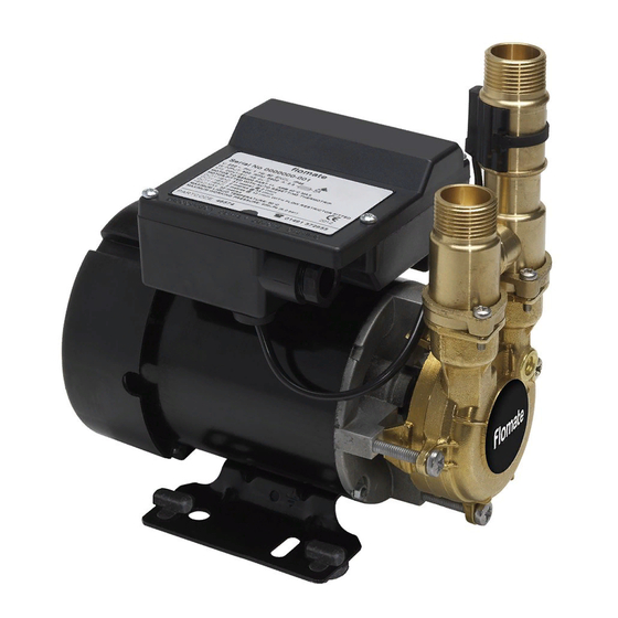
INSTALLATION INSTRUCTIONS
SERVICE KIT -
19 (Section 3 & 5)
Adhesive foam pad
(not shown)
17 (Section 5)
PCB
(not shown)
18 (Section 4)
Strainer relief bush
(not shown)
3 (Section 1)
Seal
counterface
Fig. 1
Note: 1) Items 16, 23, 24 are pre-assemble parts, see relevant section for detailed instructions.
2) See relevant section for detailed instructions.
FLOMATE, MBF 12 (Pre-November 2017) Part No.
20 (Section 3)
Capacitor (not shown)
22 (Sections 3, 4 & 5)
Screws (K40 x 16 mm)
1 (Section 1)
Woodruff key
2 (Section 1)
Thrower
23 (Section 2)
Inlet assembly
4 (Section 1)
Rotary seal
5 (Section 1)
Washer (OD ¾)
6 (Section 1)
Circlip
21 (Section 4)
Reed switch
12
16 (Section 2)
Non return
valve assembly
7 (Section 1)
'O'-ring (ID 66.4)
28457
12 (Section 2)
Screws (M4 x 16 mm)
10 (Section 2)
Clip
11 (Section 2)
Magnetic float
13 (Section 2 & 4)
Reed switch tie wrap
24 (Section 2)
Outlet assembly
14 (Section 2)
Flow regulator
15 (Section 2)
'O'-ring (ID 24.6)
8 (Section 1)
Screws M6 x 35 mm
Cont ...
Advertisement

Related Manuals for Stuart Turner FLOMATE MBF 12


Summary of Contents for Stuart Turner FLOMATE MBF 12
-
Page 1: Installation Instructions
INSTALLATION INSTRUCTIONS SERVICE KIT - 28457 FLOMATE, MBF 12 (Pre-November 2017) Part No. 12 (Section 2) Screws (M4 x 16 mm) 21 (Section 4) 19 (Section 3 & 5) Reed switch Adhesive foam pad 10 (Section 2) (not shown) 20 (Section 3) Clip Capacitor (not shown) 11 (Section 2) - Page 2 Outlet Assembly (M4 x 16) Check to see that you have all the above items and that they are not damaged. If any damage is found contact Stuart Turner Ltd within 24 hours of receipt. • PUMP PREPARATION To prepare the pump to accept the service kit parts, each pump part must be removed noting its exact position and sequence (Fig.
- Page 3 SECTION 1 - MECHANICAL SEAL REPLACEMENT The parts required to replace the seal are: ITEM ITEM Woodruff Key Circlip Thrower ‘O’-ring (ID 66.40, c/sec 1.78) Seal Counterface Screws (M6 x 35 mm) Rotary Seal Seal Applicator Tool (not shown) Washer (ID 3/8 "x OD ¾...
- Page 4 • MAINTENANCE AND CARE UPON ASSEMBLY To allow ease of assembly along with correct functioning of Applicator Tool (Item 9) the pump, the following points on assembly are necessary. • All pump parts must be free from debris and Side 2 assembled correctly.
- Page 5 SECTION 2 - VALVE REPLACEMENT The parts required to replace the valve are: ITEM ITEM Clip Non Return Valve Magnetic Float Crossflow Pipe Screw, M4 x 16 mm Inlet Assembly Reed Clamp Tie Oulet Assembly Flow Regulator - 12 l/min 23,24* ‘O’-ring, ID 13, c/sec 3 mm ‘O’-ring, ID 24.60, c/sec 2.40 *Parts pre-assembled...
- Page 6 • REASSEMBLY • Fit the flow regulator (Item 14) into new outlet assembly, fit the magnetic float (Item 11) into outlet assembly (see Fig. 10) and assemble circlip (Item 10) using fine point pliers as shown in Fig. 9. Fig. 9 Fig.
- Page 7 Note – For correct operation the NRV assembly (item 16) must be fitted with the orientation groove to the left (inlet port side) as shown in Fig. 12. Inlet Port Outlet Port Orientation groove to the left Fig. 12 For correct operation of the flow switch, the reed must be secured to the body as detailed below.
- Page 8 IMPORTANT: Take note of capacitor wiring connection and colours before removal. Disconnect and remove capacitor (item 20) and foam securing pad (item 19), make note of pad fitted position. Damaged components must be replaced. Contact Stuart Turner for advice on replacements not supplied with kit. Cont ...
- Page 9 • REASSEMBLY Reassembly is the reverse of the disassembly instructions, with new replacement parts fitted as required. Note: For correct installation the capacitor must be connected, secured and positioned as detailed (Figs. 17 & 18). Secure terminal box lid screws to a torque of 0.8 Nm (item 22). IMPORTANT NOTE: For correct pump rotation, ensure both blue wires are connected to the linked capacitor terminals as shown.
- Page 10 SECTION 4 - REED SWITCH REPLACEMENT The parts required to replace the reed switch are: ITEM ITEM Reed Switch Tie Wrap Reed Switch Strain Relief Bush Screws (K40 x 16 mm) • WIRING DIAGRAMS Fig. Pump Eire Flomate, MBF 12 ü...
- Page 11 Bush Pliers Fig. 20 Damaged components must be replaced. Contact Stuart Turner for advice on replacements not supplied with kit. • REASSEMBLY • Fit the new strain relief bush around the reed switch cable and squeeze the strain relief bush with pliers to compress the cable.
- Page 12 Fig. 23 Fig. 22 • INITIAL OPERATING INSTRUCTIONS • Consult instruction manual for commissioning instructions. • Do not run pump dry. Allow the water to be pumped to enter the pump body thus ensuring the seal is lubricated before switching the pump on. Failure to do this will damage the seal. •...
- Page 13 SECTION 5 - PRINTED CIRCUIT BOARD REPLACEMENT The parts required to replace the printed circuit board are: ITEM ITEM Printed Circuit Board Screws (K40 x 16 mm) Adhesive Foam Pad • WIRING DIAGRAM Fig. Pump Eire Flomate, MBF 12 ü ü...
- Page 14 Disconnect all wiring from terminal blocks on printed circuit board (PCB Item 17). • Remove two M4 nuts (item A) and carefully lift PCB (Item 17) away from terminal box. Damaged components must be replaced. Contact Stuart Turner for advice on replacements not supplied with kit. •...
- Page 15 Failure to do this will damage the seal. • Carefully check pump and pipework for leaks whilst pump running and stationary before leaving the installation unattended. Stuart Turner Limited reserves the right to amend specifications without notice. - 15 -...
- Page 16 Stuart Turner Ltd, Henley-on-Thames, Oxfordshire RG9 2AD ENGLAND Tel: +44 (0) 1491 572655, Fax: +44 (0) 1491 573704 info@stpumps.co.uk www.stuart-turner.co.uk Pt. No. 20003 Issue No: 4817/1-02...
Need help?
Do you have a question about the FLOMATE MBF 12 and is the answer not in the manual?
Questions and answers