Table of Contents
Advertisement
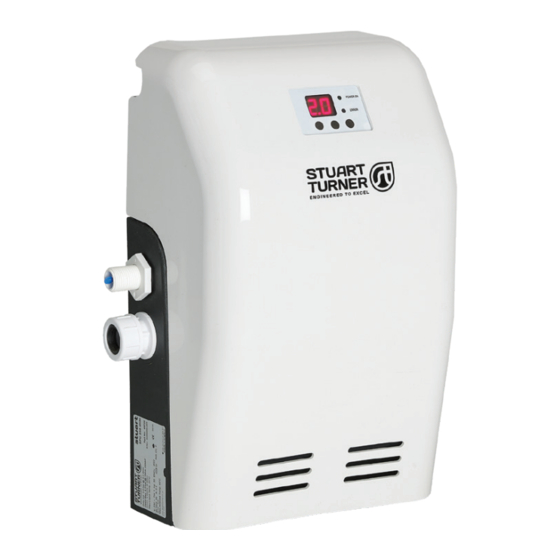
STUART
Installation, Operation & Maintenance
Instructions
Please leave this instruction booklet with the end user as it contains
important guarantee, maintenance and safety information
Read this manual carefully before commencing installation.
This manual covers the following products:
SPU 130 Mini
Pt. No. 46719
SPU 230 Mini
Pt. No. 46720
CE compliant product
2
Advertisement
Table of Contents


Need help?
Do you have a question about the Stuart SPU 130 Mini and is the answer not in the manual?
Questions and answers