Advertisement
Table of Contents
- 1 Table of Contents
- 2 Checklist
- 3 Pre-Installation
- 4 Important Facts - Read before Commencing Installation
- 5 Location
- 6 Pump Connections
- 7 Electrical Installation
- 8 Wiring Diagram
- 9 Commissioning
- 10 Maintenance
- 11 Technical Specification
- 12 Trouble Shooting
- 13 Guarantee
- 14 Declaration of Conformity
- Download this manual
Installation, Operation & Maintenance
Instructions
Please leave this instruction booklet with the owner as
it contains important guarantee, maintenance and safety
information
Read this manual carefully before commencing installation.
This manual covers the following products:
CH 4-30 B
Pt. No. 46593
CH 4-40 B
Pt. No. 46594
FOR POSITIVE OR NEGATIVE HEAD APPLICATIONS
50 Hz
CH 4-50 B
Pt. No. 46595
CH 4-60 B
Pt. No. 46610
CE compliant product
Advertisement
Table of Contents

Related Manuals for Stuart Turner CH 4-30 B


Summary of Contents for Stuart Turner CH 4-30 B
- Page 1 Please leave this instruction booklet with the owner as it contains important guarantee, maintenance and safety information Read this manual carefully before commencing installation. This manual covers the following products: CH 4-30 B CH 4-50 B Pt. No. 46593 Pt. No. 46595 CH 4-40 B CH 4-60 B Pt.
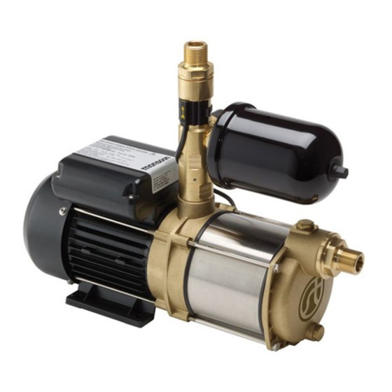
- Page 2 PRODUCT DESCRIPTION Electric motor driven centrifugal pump complete with an automatic control system, consisting of flow switch, pressure switch, pressure vessel and electronic control. APPLICATION The Stuart CH Boostamatic range is designed for pressure boosting applications in vented stored, hot or cold, clean water systems, where under gravity, no flow is available and can be used in systems where either a positive or negative head exists.
-
Page 3: Table Of Contents
CONTENTS Page Checklist ............4 Pre-Installation . -
Page 4: Checklist
IMPORTANT: With the pump removed from its packaging check for any damage prior to installation. If any damage is found contact Stuart Turner Ltd within 24 hours of receipt. 28 mm copper inlet pipework (suction). 28 mm isolating valve... -
Page 5: Pre-Installation
PRE-INSTALLATION ASSEMBLY Re-positioning of Pressure Vessel The pressure vessel can be rotated to alternative positions (Fig. 3) in the event of the factory fitted position being unsuitable for a specific installation. a) Remove pressure vessel by unscrewing anti-clockwise. b) Using a 2 mm allen key, carefully loosen all three retaining grub screws by two turns (Fig. -
Page 6: Important Facts - Read Before Commencing Installation
1 IMPORTANT FACTS: READ BEFORE COMMENCING PUMP INSTALLATION A. Water storage capacity. 1.11 The hot and cold water storage capacity (must be a minimum of 230 litres) and sufficient to meet the flow rates required by the pumped equipment and any other water using fittings and appliances, which may be operated simultaneously. -
Page 7: Location
2.21 Direction of flow: Ensure the water flow is in the direction of the arrow marked on the flow switch reed clamp (vertically upwards). 2.22 Flexible hoses: Only use the Stuart Turner hose set supplied with the pump. 2.23 Isolating valves: Separate system isolating valves (non restrictive) must be fitted to allow easy pump service. - Page 8 2 LOCATION - COLD WATER INSTALLATION Cold water pump Fig. 4 2.25 The cold water supply: Must be a DEDICATED AIR FREE supply via a tank connector, and must be positioned at a slightly lower level (25 mm minimum) than the feed pipe to the hot water cylinder. Do not connect to the mains.
- Page 9 LOCATION - HOT WATER INSTALLATION Hot water pump Fig. 5 2.26 Hot water cylinder or storage tank: When a hot water cylinder or storage tank is used, ensure the pipework size from the cold water storage to the hot water storage is of adequate size and a minimum of 28 mm. 2.27 Hot water supply: The pump must be supplied with a dedicated feed direct from the hot water cylinder or storage tank which should be via a secondary dedicated tapping (see Fig.
- Page 10 2.28 Pump Mounted Above Liquid Source (Suction Lift Installation): Note: This image is for reference only Fig. 7 Diagram showing typical Pressure Control installation with suction lift. 2.29 The pumps can be used in a suction lift installation providing the height of lift is within the limits specified in the limits of application section and the liquid to be pumped is cold water (for applications other than cold water contact Stuart Turner).
- Page 11 2.36 Non-Preferred Pump Location: The pump must be located with at least 1 metre flooded suction at all times. If it is not possible to locate the pump in the preferred area due to site limitations and it is necessary to position the unit in the loft, or in a position above the secondary tapping that feeds the pump, then there is an increased risk of air locks.
-
Page 12: Pump Connections
3 PUMP CONNECTIONS 3.11 Hose to pump: These pumps have G 1 threaded connections to accept the hoses supplied. The hose end is made water tight with a sealing washer on assembly, nip tight to 4/5 Nm for water tight seal (Do not overtighten). 3.12 Hose to pipework: Hoses terminating in G 1 threaded connections are supplied and when securing the male end to a suitable pipe fitting, seal with PTFE tape or other suitable sealant. -
Page 13: Electrical Installation
4 ELECTRICAL INSTALLATION / EARTHING 4.11 Regulations: The electrical installation must be carried out in accordance with the current national electrical regulations and installed by a qualified person. 4.12 Safety: In the interests of electrical safety a 30 mA residual current device (R.C.D. -
Page 14: Wiring Diagram
If the supply cord is to be changed or is damaged, it must be replaced with a special cord assembly available from Stuart Turner or one of their approved repairers. On disassembly note the cord retention and routing system. Re-assemble to the same pattern. -
Page 15: Commissioning
Carefully check pump and pipework for leaks whilst pump running and stationary before leaving the installation unattended. 5.15 For Further Technical Support: Phone the Stuart Turner PumpAssist team on +44 (0) 800 31 969 80. Our staff are trained to help and advise you over the phone. -
Page 16: Maintenance
6 MAINTENANCE 6.11 Disconnect electrical supply before working on the pump. 6.12 Turn off water supplies to the pump and release pressure by opening water outlets before attempting maintenance. 6.13 Inlet strainer: Incorporated in the strainer is a removable gauze filter which may require periodic cleaning. - Page 17 Air Charge Model bar (psi) CH 4-30 B 1.3 (19) CH 4-40 B 1.8 (26.1) ‘O’-Ring CH 4-50 B 2.8 (46.6) CH 4-60 B Schrader valve (under cap) Pressure vessel Detail view of ‘O’-Ring ‘O’-Ring groove Note: This image is for...
-
Page 18: Technical Specification
7 TECHNICAL SPECIFICATION CH 4-30 B CH 4-40 B CH 4-50 B CH 4-60 B Pump Model 50 Hz 50 Hz 50 Hz 50 Hz 46593 46594 46595 46610 General Guarantee 2 years WRAS approval 1601057 1601035 Features Pump type... - Page 19 Stuart Turner reserve the right to amend the specification in line with its policy of continuous development of its products. *Note: The maximum pressure that can be applied to the pump under any installation conditions. **Note: A stored water temperature of 60°C is considered sufficient to meet all normal requirements and will minimize deposition of scale in hard water areas.
-
Page 20: Trouble Shooting
Check fuse (see fuse section). Check circuit breaker is set. Check wiring connections. Pump Jammed. If motor ‘Buzzes’ switch off power and contact Stuart Turner. Damaged pressure switch. Turn off power. Release system water pressure. Turn on power, pump should start. If NOT contact Stuart Turner. - Page 21 8.11 Dry Run Protection: This pump is fitted with a safety control circuit, which will detect the following fault condition: Dry running caused by water starvation to the pump. Should the pump run out of water it will stop as part of a “protective logic sequence”, detailed below.
- Page 22 Briefly reconnect the mains power supply to the pump – the ‘power on’ light should illuminate if the pump has been correctly wired. Isolate the mains electrical power supply from the pump. Re fit the terminal box lid ensuring no cables are trapped. Re fit the four terminal box lid retaining screws, tighten to 0.8 Nm.
-
Page 23: Guarantee
Proof of purchase should accompany the returned unit to avoid delay in investigation and dealing with your claim. You should obtain appropriate insurance cover for any loss or damage which is not covered by Stuart Turner Ltd in this provision. Please record here for your records. TYPE NO. -
Page 24: Declaration Of Conformity
Signed ..........Stuart Turner are an approved company to BS EN ISO 9001:2008...
Need help?
Do you have a question about the CH 4-30 B and is the answer not in the manual?
Questions and answers