
Related Manuals for Vecow IVH-9204MX ICY


Summary of Contents for Vecow IVH-9204MX ICY
- Page 1 USER USER IVH-9204MX ICY Manual Manual Intel ® Xeon ® /Core™ i7/i5/i3 Fanless In-Vehicle Computing System EN50155 & EN45545-2 Certified, X-coded M12 PoE , 16V to 160V DC-in 1.0.0 Edition 20200205...
- Page 2 Record of Revision Version Date Remark Page Description 0.10 2020/01/30 Preliminary Release 1.00 2020/02/05 Official Release ©Vecow IVH-9204MX ICY User Manual...
- Page 3 This manual is released by Vecow Co., Ltd. for reference purpose only. All product offerings and specifications are subject to change without prior notice. It does not represent commitment of Vecow Co., Ltd. Vecow shall not be liable for direct, indirect, special, incidental, or consequential damages arising out of the use of the product or documentation or any infringements upon the rights of third parties, which may result from such use.
- Page 4 ® 6th Gen Intel Core™ i3-6100 Processor i3-6100 (3M Cache, 3.70GHz) ® 6th Gen Intel Core™ i3-6100TE Processor i3-6100TE (4M Cache, 2.70GHz) ® 8th Gen Intel Core™ i3-8100T Processor i3-8100T (XXM Cache, up to 3.10GHz) ©Vecow IVH-9204MX ICY User Manual...
- Page 5 Terminal Block 20-pin to Terminal Block 20-pin Cable, 500cm Terminal Board with One 20-pin Terminal Block Connector TMB-TMBK-20P and DIN-Rail Mounting 4G Module Mini PCIe 4G/GPS Module with Antenna WiFi & Bluetooth Mini PCIe WiFi & Bluetooth Module with Antenna ©Vecow IVH-9204MX ICY User Manual...
-
Page 6: Table Of Contents
1.5.1 Dimensions of IVH-9204MX ICYU 1.5.2 Dimensions of IVH-9204MX ICY 1.5.3 Dimensions of IVH-9204MX ICY4U 1.5.4 Dimensions of IVH-9204MX ICY4 CHAPTER 2 GETTING TO KNOW YOUR IVH-9204MX ICY 14 2.1 Packing List 2.2 Front Panel I/O & Functions 2.3 Rear Panel I/O & Functions 2.4 Main Board Expansion Connectors... - Page 7 3.7 Installing SIM Card 3.8 Installing SSD/HDD 3.9 Installing UPM 3.10 Mounting Your IVH-9204MX ICY CHAPTER 4 BIOS SETUP 4.1 Entering BIOS Setup 4.2 Main 4.3 Advanced 4.4 Chipset 4.5 Security 4.6 Boot 4.7 Save & Exit APPENDIX A : Isolated Guide...
-
Page 8: Chapter 1 General Introduction
GENERAL INTRODUCTION 1.1 Overview Vecow IVH-9204MX ICY Series is a trusted and powerful rugged in-vehicle computing engine in the market. Flexible LGA1151 Socket supports workstation- ® ® grade Intel Xeon /Core™ i7/i5/i3 processor (Kaby Lake-S/Skylake-S) running ® with advanced Intel C236 chipset and dual-channel DDR4 2400/2133 ®... -
Page 9: Features
• 32 Isolated DIO, 8 USB 3.0, 4 COM, 3 Mini PCIe • 16V to 160V DC Power Input with 4kV DC Isolation, up to 500V Surge Protection • Configurable Ignition Power Control • UPS supported (Optional) ©Vecow IVH-9204MX ICY User Manual GENERAL INTRODUCTION... -
Page 10: Product Specification
LAN 1 Intel I219LM GigE LAN supports iAMT 11.0 ® LAN 2 Intel I210 GigE LAN PoE (M12) ® GigE IEEE 802.3at (25.5W/48V) PoE by Intel I210, M12 LAN 3 to LAN 6 Connector ©Vecow IVH-9204MX ICY User Manual GENERAL INTRODUCTION... - Page 11 Operating Temperature 0°C to 40°C (32°F to 104°F) Storage Temperature -40°C to 85°C (-40°F to 185°F) Humidity 5% to 95% humidity, non-condensing Relative Humidity 95% at 40°C Shock IEC 61373 Vibration IEC 61373 CE, FCC, EN50155:2017, EN50121-3-2, EN45545-2 ©Vecow IVH-9204MX ICY User Manual GENERAL INTRODUCTION...
-
Page 12: Specifications Of Ivh-9204Mx Icy
1.3.2 Specifications of IVH-9204MX ICY System ® ® Quad Core 7th/6th Gen Intel Xeon /Core™ i7/i5/i3 Processor Processor (Kaby Lake-S/Skylake-S) ® Chipset Intel C236 BIOS IT8786E • DDR4 2400/2133MHz Memory • Up to 64GB • 2 260-pin SO-DIMM Socket (ECC/Non-ECC) - Page 13 -40°C to 45°C (-40°F to 113°F) Storage Temperature -40°C to 85°C (-40°F to 185°F) Humidity 5% to 95% humidity, non-condensing Relative Humidity 95% at 55°C Shock IEC 61373 Vibration IEC 61373 CE, FCC, EN50155:2017, EN50121-3-2, EN45545-2 ©Vecow IVH-9204MX ICY User Manual GENERAL INTRODUCTION...
-
Page 14: Specifications Of Ivh-9204Mx Icy4U
LAN 1 Intel I219LM GigE LAN supports iAMT 11.0 ® LAN 2 Intel I210 GigE LAN PoE (M12) ® GigE IEEE 802.3at (25.5W/48V) PoE by Intel I210, M12 LAN 3 to LAN 6 Connector ©Vecow IVH-9204MX ICY User Manual GENERAL INTRODUCTION... - Page 15 Operating Temperature 0°C to 40°C (32°F to 104°F) Storage Temperature -40°C to 85°C (-40°F to 185°F) Humidity 5% to 95% humidity, non-condensing Relative Humidity 95% at 40°C Shock IEC 61373 Vibration IEC 61373 CE, FCC, EN50155:2017, EN50121-3-2, EN45545-2 ©Vecow IVH-9204MX ICY User Manual GENERAL INTRODUCTION...
-
Page 16: Specifications Of Ivh-9204Mx Icy4
® LAN 1 Intel I219LM GigE LAN supports iAMT 11.0 ® LAN 2 Intel I210 GigE LAN PoE (M12) ® LAN 3 to LAN 6 GigE IEEE 802.3at (25.5W/48V) PoE by Intel I210 ©Vecow IVH-9204MX ICY User Manual GENERAL INTRODUCTION... - Page 17 -40°C to 45°C (-40°F to 113°F) Storage Temperature -40°C to 85°C (-40°F to 185°F) Humidity 5% to 95% humidity, non-condensing Relative Humidity 95% at 55°C Shock IEC 61373 Vibration IEC 61373 CE, FCC, EN50155:2017, EN50121-3-2, EN45545-2 ©Vecow IVH-9204MX ICY User Manual GENERAL INTRODUCTION...
-
Page 18: Supported Cpu List
Core™ i5-6500TE Up to 3.3GHz ® Intel Core™ i3-7101E Up to 3.9GHz ® Intel Core™ i3-7101TE Up to 3.4GHz ® Intel Core™ i3-6100 Up to 3.7GHz Intel ® Core™ i3-6100TE Up to 2.7GHz ©Vecow IVH-9204MX ICY User Manual GENERAL INTRODUCTION... -
Page 19: Mechanical Dimension
1.5.1 Dimensions of IVH-9204MX ICYU Unit : mm (inch) 297.0 (11.69”) 282.0 (11.10”) 260.0 (10.24”) 5.0 (0.20”) A Detail 1.5.2 Dimensions of IVH-9204MX ICY Unit : mm (inch) 297.0 (11.69”) 282.0 (11.10”) 260.0 (10.24”) 5.0 (0.20”) A Detail ©Vecow IVH-9204MX ICY User Manual... -
Page 20: Dimensions Of Ivh-9204Mx Icy4U
1.5.3 Dimensions of IVH-9204MX ICY4U 297.0 (11.69”) 282.0 (11.10”) 260.0 (10.24”) 5.0 (0.20”) A Detail 1.5.4 Dimensions of IVH-9204MX ICY4 297.0 (11.69”) 282.0 (11.10”) 260.0 (10.24”) 5.0 (0.20”) A Detail ©Vecow IVH-9204MX ICY User Manual GENERAL INTRODUCTION... -
Page 21: Chapter 2 Getting To Know Your Ivh-9204Mx Icy
GETTING TO KNOW YOUR IVH-9204MX ICY 2.1 Packing List Item Description IVH-9200 series In-Vehicle Fanless Embedded System (According to the configuration you order, the IVH-9200 series may contain SSD/ HDD and DDR4 SO-DIMM. Please verify these items if necessary.) IVH-9204MX-ICY/IVH-9204MX-ICYU-Accessory box, which contains •... -
Page 22: Front Panel I/O & Functions
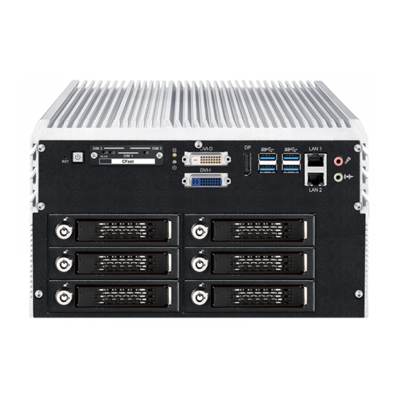
2.2 Front Panel I/O & Functions In Vecow IVH-9200 series family, all I/O connectors are located on front panel and rear panel. Most of the general connections to computer device, such as USB, LAN Jack, Audio, Display Port, DVI-I, DVI-D and other additional storage, are placed on the front panel. - Page 23 The pinouts of CFast port are listed as follows : Pin No. Description Pin No. Description SATA_TXP4 SATA_TXN4 CFAST_LED SATA_RXN4 PC10 SATA_RXP4 PC11 PC12 PC13 +3.3V PC14 +3.3V PC15 PC16 PC17 ©Vecow IVH-9204MX ICY User Manual GETTING TO KNOW YOUR IVH-9204MX ICY...
- Page 24 1920 x 1200 resolution. The DVI is automatically selected according to the connected display. You will need a DVI-D cable when connecting to a display device. ©Vecow IVH-9204MX ICY User Manual GETTING TO KNOW YOUR IVH-9204MX ICY...
- Page 25 Multi-Stream Transport Display Resolutions Table : Multi-Stream Transport Display Max. Resolution One panel Display 4096 x 2304 @60Hz Two panel Displays concurrently 2880 x 1800 @60Hz Three panel Displays concurrently 2304 x 1440 @60Hz ©Vecow IVH-9204MX ICY User Manual GETTING TO KNOW YOUR IVH-9204MX ICY...
- Page 26 The pin-outs of LAN 1 and LAN 2 are listed as follows : Pin No. 10/100 Mbps 1000Mbps E_TX+ MDI0_P E_TX- MDI0_N E_RX+ MDI1_P ----- MDI2_P ----- MDI2_N E_RX- MDI1_N ----- MDI3_P ----- MDI3_N ©Vecow IVH-9204MX ICY User Manual GETTING TO KNOW YOUR IVH-9204MX ICY...
- Page 27 SIM 1 WLAN CFast DVI-I LAN 2 Mini PCIe Slot/SIM Slot/WLAN LED Mapping Table : IVH-9204MX ICYU and IVH-9204MX ICY can't use SIM3 Mini PCIe Mini PCIe 1 SIM 1 (CN11) Mini PCIe 2 SIM 2 (CN12) Mini PCIe 3 SIM 3 (CN13) ©Vecow IVH-9204MX ICY User Manual...
- Page 28 CFast DVI-I LAN 2 There are 4 front-access 2.5" SSD/HDD trays in the front side of IVH-9200. Just trigger to open the SSD/HDD tray, up to 8TB is available. ©Vecow IVH-9204MX ICY User Manual GETTING TO KNOW YOUR IVH-9204MX ICY...
-
Page 29: Rear Panel I/O & Functions
(instant off or delay 4 second) and suspend mode. Pin No. Definition Ignition External Power Button V+ External Power Button V- ©Vecow IVH-9204MX ICY User Manual GETTING TO KNOW YOUR IVH-9204MX ICY... - Page 30 ----------- ----------- CTS+ ----------- ----------- CTS- ----------- COM 3 & COM 4 MB connector table : COM Port MB Connector COM Port MB Connector COM 3 COM 4 CN10 ©Vecow IVH-9204MX ICY User Manual GETTING TO KNOW YOUR IVH-9204MX ICY...
- Page 31 IVH-9200. It is also compliant with the requirements of Super Speed (SS), High Speed (HS), Full Speed (FS) and Low Speed (LS). ©Vecow IVH-9204MX ICY User Manual GETTING TO KNOW YOUR IVH-9204MX ICY...
- Page 32 COM 4 COM 3 V+ V - There are 4 X-coded M12 connectors in the rear side of IVH-9204MX ICY. It supports IEEE 802.3at (PoE ) Power over Ethernet (PoE) connection delivering up to 30.4W/54V per port and 1000BASE-T GigE data signals over standard Ethernet ®...
- Page 33 OUTPUT 0 SIO_GPO70 OUTPUT 1 SIO_GPO71 OUTPUT 2 SIO_GPO72 OUTPUT 3 SIO_GPO73 OUTPUT 4 SIO_GPO74 OUTPUT 5 SIO_GPO75 OUTPUT 6 SIO_GPO76 OUTPUT 7 SIO_GPO77 DIO1_GND DIO1_VDC (6 ~ 48V Input) ©Vecow IVH-9204MX ICY User Manual GETTING TO KNOW YOUR IVH-9204MX ICY...
- Page 34 DIO_VDC (Pin 20) 6-48V DC DO (Pin 11-18) DIO_GND (Pin 10, 19) Source Mode Device DIO Connector (PNP) DIO_VDC (Pin 20) 6-48V DC DO (Pin 11-18) DIO_GND (Pin 10, 19) ©Vecow IVH-9204MX ICY User Manual GETTING TO KNOW YOUR IVH-9204MX ICY...
-
Page 35: Main Board Expansion Connectors
2.4.1 Inside View of IVH-9200 Main Board with Connector Location CN25 CN10 CN15 FAN2 JP10 SODIMM2 CN18 SATA2 SATA1 FAN1 SODIMM1 SATA4 SATA3 Mini PCIe 2 Mini PCIe 3 Mini PCIe 1 BIOS Battery M2_CN1 ©Vecow IVH-9204MX ICY User Manual GETTING TO KNOW YOUR IVH-9204MX ICY... - Page 36 The pin-outs of Miscellaneous port are listed in following table : Group Pin No. Description HDD_LED_P HDD LED HDD_LED_N FP_RST_BTN_N RESET BUTTON Ground PWR_LED_P POWER LED PWR_LED_N FP_PWR_BTN_IN POWER BUTTON Ground ©Vecow IVH-9204MX ICY User Manual GETTING TO KNOW YOUR IVH-9204MX ICY...
- Page 37 SODIMM1 Slot Description SODIMM_1 DDR4 Channel A SODIMM_2 DDR4 Channel B 2.4.5 BIOS Socket If the BIOS need to be changed, please contact the Vecow RMA service team. BIOS ©Vecow IVH-9204MX ICY User Manual GETTING TO KNOW YOUR IVH-9204MX ICY...
- Page 38 There are 2 HDD power header on board and each power header supports two 2.5" SATA HDD. Pin No. Description Pin No. Description +V5 (Max. 4A) Ground Ground +V12 (Max. 1.5A) ©Vecow IVH-9204MX ICY User Manual GETTING TO KNOW YOUR IVH-9204MX ICY...
- Page 39 The USB interface is accessed through one standard USB 2.0 connector. This USB 2.0 does not support wake up function. CN18 Pin No. Description Pin No. Description USB +VCC DATA- (+V5/Max. 0.5A) DATA+ Ground ©Vecow IVH-9204MX ICY User Manual GETTING TO KNOW YOUR IVH-9204MX ICY...
- Page 40 Support hot removal : The removal of a SATA device from a powered backplane, without first being placed in a quiescent state. M2_CN1 Model No. Definition S20/S30 16GB M2DOM S20/S30 3ME3 32GB S20/S30 64GB 128GB ©Vecow IVH-9204MX ICY User Manual GETTING TO KNOW YOUR IVH-9204MX ICY...
- Page 41 USB_D+ USB_D- PETp0 PETn0 SMB_DATA SMB_CLK +1.5V PERn0 PERp0 +3.3Vaux PERST# Reserved reserved Reserved Mechanical Key UIM_VPP REFCLK+ UIM_RESET REFCLK- UIM_CLK UIM_DATA CLKREQ# UIM_PWR Reserved 1.5V Reserved WAKE# 3.3Vaux ©Vecow IVH-9204MX ICY User Manual GETTING TO KNOW YOUR IVH-9204MX ICY...
- Page 42 The system's real-time clock is powered by a lithium battery. It is Equipped with Panasonic BR2032 190mAh lithium battery. It is recommended that you not replace the lithium battery on your own. If the battery needs to be changed, please contact the Vecow RMA service team. Battery 2.4.12 FAN Header Fan power connector supports for additional thermal requirements.
- Page 43 Rear PoE LAN 4 Intel I210 Rear PoE LAN 5 Intel I210 Rear PoE LAN 6 Intel I210 Pin No. Description Pin No. Description SPD0 SPD1 SPD2 SPD3 Ground Ground ©Vecow IVH-9204MX ICY User Manual GETTING TO KNOW YOUR IVH-9204MX ICY...
- Page 44 2.4.16 Wide range power module (WPM-110) 16V to 160V DC Power Input with 4242V DC Isolation & 500V DC Surge Protection. HDD_PWR1 Connector Description Input Output HDD_PWR1 HDD Power ©Vecow IVH-9204MX ICY User Manual GETTING TO KNOW YOUR IVH-9204MX ICY...
- Page 45 VBAT_EN VBAT_TYPE VBAT_STAT1 VBAT_NTC VBAT_STAT2 VBAT_PG# BAT1 (Battery) : BAT2 (Battery) : Pin No. Description Pin No. Description VBAT_0 VBAT_1 VBAT_1 VBAT_2 BAT3 (Battery): Pin No. Description VBAT_0 VBAT_1 ©Vecow IVH-9204MX ICY User Manual GETTING TO KNOW YOUR IVH-9204MX ICY...
-
Page 46: Main Board Jumper And Dip Switch Settings
You may configure your card to match the needs of your application by DIP switch. As below show the deep switch on and off. 1 : OFF 1 : ON 1 : ON 2 : OFF 2 : OFF 2 : ON ©Vecow IVH-9204MX ICY User Manual GETTING TO KNOW YOUR IVH-9204MX ICY... - Page 47 5 - 6 RI (Default) Pin Header Pin No. Description 1 - 2 +5V (1A max.) COM 6 3 - 4 +12V (0.5A max.) 5 - 6 RI (Default) ©Vecow IVH-9204MX ICY User Manual GETTING TO KNOW YOUR IVH-9204MX ICY...
- Page 48 PoE power on at standby power ready PoE power on after system power on (Default) 2.5.5 Clear CMOS/ME Switch JP1 : Setting Function *Normal (Default) Clear CMOS JP2 : Setting Function *Normal (Default) Clear ME ©Vecow IVH-9204MX ICY User Manual GETTING TO KNOW YOUR IVH-9204MX ICY...
-
Page 49: Ignition Control
2.6.1 Adjust Ignition Control Modes IVH-9200 series provides 16 modes of different power on/off delay periods adjustable via SW2 switch. The default rotary switch is set to 0 in ATX/AT power mode. ©Vecow IVH-9204MX ICY User Manual GETTING TO KNOW YOUR IVH-9204MX ICY... - Page 50 30 minutes 5 seconds 1 hour 10 seconds 2 hours 10 seconds 4 hours 10 seconds 6 hours 10 seconds 8 hours 10 seconds 12 hours 10 seconds 24 hours ©Vecow IVH-9204MX ICY User Manual GETTING TO KNOW YOUR IVH-9204MX ICY...
- Page 51 3. For proper ignition control, the power button setting should be "Power Down" mode. In Windows for example, you need to set "When I press the power button" to Shut down. ©Vecow IVH-9204MX ICY User Manual GETTING TO KNOW YOUR IVH-9204MX ICY...
- Page 52 The Low Battery Detection is implemented in the ignition control MCU FW and as a default function. Note : Battery Voltage Thresholds 10.5 to 15V 21.5 to 30V ©Vecow IVH-9204MX ICY User Manual GETTING TO KNOW YOUR IVH-9204MX ICY...
-
Page 53: Chapter 3 System Setup
SYSTEM SETUP 3.1 How to Open Your IVH-9204MX ICY Step 1 Remove three #6-32 screws. Step 2 Finish. ©Vecow IVH-9204MX ICY User Manual SYSTEM SETUP... - Page 54 Step 3 Remove eight flat head #6-32 screws. Step 4 Finish. ©Vecow IVH-9204MX ICY User Manual SYSTEM SETUP...
- Page 55 Step 5 Remove SATA, SATA power cable. Step 6 Remove SSD tray module. Step 7 Finish. ©Vecow IVH-9204MX ICY User Manual SYSTEM SETUP...
-
Page 56: Installing Cpu
3.2 Installing CPU Step 1 Remove five #6-32 screws. Step 2 Finish. ©Vecow IVH-9204MX ICY User Manual SYSTEM SETUP... - Page 57 Step 3 Remove ATX (red) and COM (blue) cable. Step 4 Remove COM cable. ©Vecow IVH-9204MX ICY User Manual SYSTEM SETUP...
- Page 58 Step 5 Remove rear panel. Step 6 Finish Step1~5. ©Vecow IVH-9204MX ICY User Manual SYSTEM SETUP...
- Page 59 Step 7 Remove seven #6-32 screws. Step 8 Remove front panel. ©Vecow IVH-9204MX ICY User Manual SYSTEM SETUP...
- Page 60 Step 9 Remove extender. Step 10 Remove #6-32 screw. ©Vecow IVH-9204MX ICY User Manual SYSTEM SETUP...
- Page 61 Step 11 Remove #6-32 screw. Step 12 Put out extender. ©Vecow IVH-9204MX ICY User Manual SYSTEM SETUP...
- Page 62 Step 13 Remove SATA, SATA power cable. Step 14 Finish Step9~13. ©Vecow IVH-9204MX ICY User Manual SYSTEM SETUP...
- Page 63 Step 15 Remove one flat head #6-32 and put out chock bracket. Step 16 Remove two M3*6L Ni+Ny screws on the M12 card. ©Vecow IVH-9204MX ICY User Manual SYSTEM SETUP...
- Page 64 Step 17 Put out M12 card. Step 18 Remove two stand off (red), three M3 spring screws (blue) and seven M3*6L screws (yellow). ©Vecow IVH-9204MX ICY User Manual SYSTEM SETUP...
- Page 65 Step 19 Pick up the mother board. Step 20 Open CPU slot. (Be careful CPU pin) ©Vecow IVH-9204MX ICY User Manual SYSTEM SETUP...
- Page 66 Step 21 Install CPU on the slot. Step 22 Finish. Step 23 Close CPU slot and finish. ©Vecow IVH-9204MX ICY User Manual SYSTEM SETUP...
-
Page 67: Installing Ddr4 So-Dimm Modules
3.3 Installing DDR4 SO-DIMM Modules Step 1 Install DDR4 RAM module into SO-DIMM slot. Step 2 Make sure the RAM module is locked by the memory slot. ©Vecow IVH-9204MX ICY User Manual SYSTEM SETUP... -
Page 68: Installing Mini Pcie Card
3.4 Installing Mini PCIe Card Step 1 Install Mini PCIe card into the Mini PCIe socket. Step 2 Fasten one M2.5 screw. ©Vecow IVH-9204MX ICY User Manual SYSTEM SETUP... -
Page 69: Installing Antenna Cable
3.5 Installing Antenna Cable Step 1 Check Antenna cable and washers. Step 2 Put Antenna cable connector into the hole on the rear panel. Step 3 Fasten the washer on Antenna cable connector. ©Vecow IVH-9204MX ICY User Manual SYSTEM SETUP... -
Page 70: Installing Cfast Card
Step 1 Remove 2 pcs F-M3x4 screws on CFast & SIM cover. Step 2 Before inserting CFast & SIM Cards, make sure IVH-9200 power is not plugged. Step 3 Insert CFast card and push to lock. ©Vecow IVH-9204MX ICY User Manual SYSTEM SETUP... -
Page 71: Installing Sim Card
Step 1 Remove two F-M3x4 screws on CFast & SIM cover. Step 2 Before inserting SIM Card, make sure the system power is not plugged. Step 3 Insert SIM card and push to lock. ©Vecow IVH-9204MX ICY User Manual SYSTEM SETUP... -
Page 72: Installing Ssd/Hdd
3.8 Installing SSD/HDD Step 1 Push button to eject. Step 2 Open the tray. ©Vecow IVH-9204MX ICY User Manual SYSTEM SETUP... - Page 73 Step 3 Pull out the tray. Step 4 The tray accommodates 2.5” drives up to 15mm height. ©Vecow IVH-9204MX ICY User Manual SYSTEM SETUP...
- Page 74 Step 5 Use the included M3*4 flat head screws to install the drive onto the tray. Step 6 Use the included M3*4 flat head screws to install the drive onto the tray. ©Vecow IVH-9204MX ICY User Manual SYSTEM SETUP...
- Page 75 Step 7 Install the tray. Step 8 Close the door. ©Vecow IVH-9204MX ICY User Manual SYSTEM SETUP...
- Page 76 Step 9 Can use key to locked. Step 10 Finish. ©Vecow IVH-9204MX ICY User Manual SYSTEM SETUP...
-
Page 77: Installing Upm
3.9 Installing UPM Step 1 UPM module. Step 2 UPM Bracket. Step 3 Use M3*4 flat head screws to install the UPM bracket. ©Vecow IVH-9204MX ICY User Manual SYSTEM SETUP... - Page 78 Step 4 Install cable to UPM V-IN. Step 5 Remove three pcs PH M3*6L Ni+Ny screws. Step 6 Install three M3*15L stand off. ©Vecow IVH-9204MX ICY User Manual SYSTEM SETUP...
- Page 79 Step 7 Put on UPM module with bracket. Step 8 Fasten three M3*6L Ni+Ny screws. ©Vecow IVH-9204MX ICY User Manual SYSTEM SETUP...
- Page 80 Step 9 Remove ATX cable (red) Step 10 UPM V-in cable (red) then into UPM V-out (blue). WPM-110 V-out (blue). Step 11 Finish. ©Vecow IVH-9204MX ICY User Manual SYSTEM SETUP...
-
Page 81: Mounting Your Ivh-9204Mx Icy
3.10 Mounting Your IVH-9204MX ICY Step 1 Ensure the screw holes on the right and left sides of upper case match the ones on IVH-9200 wall mount bracket. Fasten ten #6-32 screws. ©Vecow IVH-9204MX ICY User Manual SYSTEM SETUP... -
Page 82: Chapter 4 Bios Setup
Figure 4-1 : Entering Setup Screen BIOS provides an interface for users to check and change system configuration. The BIOS setup program is accessed by pressing the <Del> key when POST display output is shown. ©Vecow IVH-9204MX ICY User Manual BIOS SETUP... -
Page 83: Main
Set the time. Use <Tab> to switch between time elements. 4.3 Advanced Figure 4-3 : BIOS Advanced Menu Select advanced tab to enter advanced BIOS setup options, such as CPU configuration, SATA configuration, and USB configuration. ©Vecow IVH-9204MX ICY User Manual BIOS SETUP... - Page 84 Technology). When disabled only one thread per core is enabled. Enable/disable CPU Advanced Encryption Standard instructions. Intel Trusted Execution Technology ® Enables utilization of additional hardware capabilities provided by Intel Trusted Execution Technology. Changes require a full power cycle to take effect. ©Vecow IVH-9204MX ICY User Manual BIOS SETUP...
- Page 85 C states Enable or disable CPU C states. Enhanced C-states Enable/disable C1E. When enabled, CPU will switch to minimum speed when all cores enter C-State. Thermal Save Mode Enable/Disable Thermal Save Mode support. ©Vecow IVH-9204MX ICY User Manual BIOS SETUP...
- Page 86 MEBx Setup. AMT Configuration ® Configure Intel Active Management Technology Parameters. ME Unconfig on RTC Clear State Disabling this option will cause ME not to unconfigure on RTC clear. ©Vecow IVH-9204MX ICY User Manual BIOS SETUP...
- Page 87 Enables or disables S3 video repost. 4.3.6 SMART Settings Figure 4-3-6 : SMART Settings SMART Self Test Run SMART self test on all HDDs during POST. 4.3.7 IT8786 Super IO Configuration Figure 4-3-7 : IT8786 Super IO Settings ©Vecow IVH-9204MX ICY User Manual BIOS SETUP...
- Page 88 (Range : 10 ~ 80) PWM Start Value (%) Default PWM Value of Fan. (Range : 15% ~ 100%) Full Speed Temperature Temperature Limit value of Fan Full Speed (Degree C). (Range : 50 ~ 90) ©Vecow IVH-9204MX ICY User Manual BIOS SETUP...
- Page 89 These settings specify how the host computer and the remote computer (which the user is using) will exchange data. Both computers should have the same or compatible settings. 4.3.10 Intel TXT Information Figure 4-3-10 : Intel TXT Information Display Intel TXT information. ©Vecow IVH-9204MX ICY User Manual BIOS SETUP...
- Page 90 4.3.12 PCI Subsystem Setting Figure 4-3-12 : PCI Subsystem Settings Above 4G Decoding Globally Enables or Disables 64bit capable Devices to be Decoded in Above 4G Address Space (Only if System Supports bot PCI Decoding) ©Vecow IVH-9204MX ICY User Manual BIOS SETUP...
- Page 91 IP6 Configuration Policy Set IP6 Configuration Policy. PXE boot wait time Wait time to press ESC key to abort the PXE boot. Media detect count Number of times presence of media will be checked. ©Vecow IVH-9204MX ICY User Manual BIOS SETUP...
- Page 92 Controls the execution of UEFI and Legacy Storage OpROM. Video Allows more than two frequency ranges to be supported. Other PCI devices Determines OpROM execution policy for devices other than network, storage, or video. ©Vecow IVH-9204MX ICY User Manual BIOS SETUP...
- Page 93 Maximum time the device will take before it properly reports itself to the Host Controller. 'Auto' uses default value, for a root port it is 100 ms, for a hub port the delay is taken from the hub descriptor. ©Vecow IVH-9204MX ICY User Manual BIOS SETUP...
-
Page 94: Chipset
Above 4GB MMIO BIOS assignment Enable/disable above 4GB MemoryMappedIO BIOS assignment. This is disabled automatically when aperture size is set to 2048MB. 4.4.1.1 Memory Configuration Figure 4-4-1-1 : Memory Information Displays memory information. ©Vecow IVH-9204MX ICY User Manual BIOS SETUP... - Page 95 2048MB aperture. To use this feature, please disable CSM Support. DVMT Pre-Allocated Select DVMT 5.0 Pre-Allocated (Fixed) Graphics Memory size used by the Internal Graphics Device. DVMT Total Gfx Mem Select DVMT5.0 Total Graphic Memory size used by the Internal Graphics Device. ©Vecow IVH-9204MX ICY User Manual BIOS SETUP...
- Page 96 Specify what state to go to when power is re-applied after a power failure (G3 state). S0 State : Always turn-on the system when power source plugged-in. S5 State : Always turn-off the system when power source plugged-in. ©Vecow IVH-9204MX ICY User Manual BIOS SETUP...
- Page 97 Enable/Disable the control of Active State Power Management on SA side of the DMI Link. Native PCIE Enable PCIE Express Native Support Enable/Disable. PCI Express device settings Bios options for PCI Express device setting. ©Vecow IVH-9204MX ICY User Manual BIOS SETUP...
- Page 98 SATA Device Type Identifies that the SATA port is connected to solid state drive or hard disk drive. Topology Identify the SATA Topology if it is Default or ISATA or Flex or DirectConnect or M2. ©Vecow IVH-9204MX ICY User Manual BIOS SETUP...
-
Page 99: Security
Enable/disable the PCH BIOS Lock Enable (BLE bit) feature. 4.5 Security Figure 4-5 : BIOS Security Menu Administrator Password Set administrator password. User Password Set user password. Secure Boot Customizable Secure Boot Settings. ©Vecow IVH-9204MX ICY User Manual BIOS SETUP... - Page 100 Secure Boot Mode Secure Boot mode selector Standard/Custom. In custom mode Secure Boot Variables can be configured without authentication. Key Management Enables expert users to modify Secure boot policy variables without full authentication. ©Vecow IVH-9204MX ICY User Manual BIOS SETUP...
-
Page 101: Boot
Boot Option Sets the system boot order. New Boot Option Policy Controls the placement of newly detected UEFI boot options. Hard Drive BBS Priorities Set the order of the Legacy devices in this group. ©Vecow IVH-9204MX ICY User Manual BIOS SETUP... -
Page 102: Save & Exit
Restore/Load Default values for all the setup options. Save as User Defaults Save the changes done so far as User Defaults. Restore User Defaults Restore the User Defaults to all the setup options. ©Vecow IVH-9204MX ICY User Manual BIOS SETUP... -
Page 103: Appendix A : Isolated Guide
DIO 12 DI 5 DIO 5 DO 5 DIO 13 DI 6 DIO 6 DO 6 DIO 14 DI 7 DIO 7 DO 7 DIO 15 DI COM DIO_GND DIO_GND DIO_GND DIO_GND External VDC ©Vecow IVH-9204MX ICY User Manual Appendix A... - Page 104 DIO Connector (NPN, Default) DIO_VDC (Pin 20) 6-48V DC DO (Pin 11-18) DIO_GND (Pin 10, 19) Source Mode Device DIO Connector (PNP) DIO_VDC (Pin 20) 6-48V DC DO (Pin 11-18) DIO_GND (Pin 10, 19) ©Vecow IVH-9204MX ICY User Manual Appendix A...
- Page 105 Runtime folder include head file for software developer or System Integration. Sample folder include sample program, driver library, and API library. Source folder include sample program source code that compile on Visual Studio 2008. ©Vecow IVH-9204MX ICY User Manual Appendix A...
- Page 106 A.4 Sample Sample folder include x32 and x64 versions, as shown below : Sample IVH9K2.exe, as shown below : ©Vecow IVH-9204MX ICY User Manual Appendix A...
- Page 107 DO/DIO pin writable check button (pin 18 ~ pin 11/pin 18 ~ pin 11, pin 8 ~ pin 1) : User setting, DO/DIO pin writable of DIO configuration. Use for Read (DIO)/Write button activate. ©Vecow IVH-9204MX ICY User Manual Appendix A...
- Page 108 POE output text (read only) : POE output state with configuration. Use for Write button activate. POE input port texts (read only, port 4 ~ port 1) : POE input port state Use for Read button activate. ©Vecow IVH-9204MX ICY User Manual Appendix A...
- Page 109 User setting, POE port writable of POE configuration. Use for Write button activate. POE port mode check button (port 4 ~ port 1) : User setting, POE port mode of POE configuration. Use for Write button activate. ©Vecow IVH-9204MX ICY User Manual Appendix A...
-
Page 110: Appendix B : Software Functions
Mask ([15:0]) : In/Out, pin setting by hexadecimal bitmask 1 : Output; 0 : Input Return : TRUE (1) : Success; FALSE (0) : Fail (Initial error, or call by pointer error, or hardware problem) ©Vecow IVH-9204MX ICY User Manual Appendix B... - Page 111 DO ([7:0]): Output state, pin setting by hexadecimal bitmask 1 : High; 0 : Low Return : TRUE (1) : Success; FALSE (0) : Fail (Initial error, or call by pointer error, or hardware problem) ©Vecow IVH-9204MX ICY User Manual Appendix B...
- Page 112 Unit : second. (Range : 1 ~ 65535 sec, 1093 ~ 65535 min (=65580 ~ 3932100 sec)) Return : TRUE (1) : Success; FALSE (0) : Fail (Initial error, or setup 0 error, or hardware problem) ©Vecow IVH-9204MX ICY User Manual Appendix B...
- Page 113 POE ([3:0]) : POE state, pin setting by hexadecimal bitmask 1 : On; 0 : Off Return : TRUE (1) : Success; FALSE (0) : Fail (Initial error, or out of range error, or hardware problem) ©Vecow IVH-9204MX ICY User Manual Appendix B...
-
Page 114: Appendix C : Raid Functions
The instructions are as follows : 1. To install Chipset driver 2. To install VGA driver 3. To install ME driver (if available) 4. To install Network driver 5. To install Audio driver ©Vecow IVH-9204MX ICY User Manual Appendix C... - Page 115 C.6 To Create RAID Volume on "Rapid Storage Technology" Software IVH-9200 is featured with four SATA HDDs for RAID volume, so there are three options for choose on this page. Let's take RAID 1 as example, please select "RAID 1". ©Vecow IVH-9204MX ICY User Manual Appendix C...
- Page 116 Then add "Logical Device" for Windows access. C.8 If One SATA HDD on RAID Volume is Out-of-use After RAID 1 volume created, you can see the figure of SATA device allocation. HDD CAUTION Sign ©Vecow IVH-9204MX ICY User Manual Appendix C...
- Page 117 There is a warning will pop-up to ask you if the disk is not a member of original RAID volume. If you press "Rebuild", it will replace the broken SATA HDD to the last one SATA HDD of RAID volume. ©Vecow IVH-9204MX ICY User Manual Appendix C...
-
Page 118: Appendix D : Power Consumption
1.0 Gbps LAN 3 (i210) 1.0 Gbps LAN 4 (i210) 1.0 Gbps LAN 5 (i210) 1.0 Gbps LAN 6 (i210) 1.0 Gbps Graphics output Power plan Balance (Windows10 Power Plan) Power Source Chroma 62006P-100-25 ©Vecow IVH-9204MX ICY User Manual Appendix D... - Page 119 Consumption Current Consumption Core™ 10.240A 61.44W 12.649A 75.89W i7-6700 Core™ 6.663A 59.97W 8.164A 73.48W i7-6700 Core™ 4.898A 58.78W 6.079A 72.95W i7-6700 Core™ 2.523A 60.55W 3.084A 74.02W i7-6700 Core™ 1.744A 62.78W 2.149A 77.36W i7-6700 ©Vecow IVH-9204MX ICY User Manual Appendix D...
- Page 120 Consumption Current Consumption Core™ i5-6500TE 5.687A 34.12W 8.032A 48.19W Core™ i5-6500TE 3.723A 33.51W 5.326A 47.93W Core™ i5-6500TE 2.823A 33.88W 3.887A 46.64W Core™ i5-6500TE 1.489A 35.74W 1.994A 47.86W Core™ i5-6500TE 1.042A 37.53W 1.408A 50.69W ©Vecow IVH-9204MX ICY User Manual Appendix D...
- Page 121 Consumption Current Consumption Core™ i3-6100 7.032A 42.19W 8.823A 52.94W Core™ i3-6100 4.787A 43.08W 5.786A 52.07W Core™ i3-6100 3.586A 43.03W 4.321A 51.85W Core™ i3-6100 1.852A 44.45W 2.362A 56.69W Core™ i3-6100 1.286A 46.30W 1.592A 57.31W ©Vecow IVH-9204MX ICY User Manual Appendix D...
-
Page 122: Appendix E : Supported Memory & Storage List
Memory Test version : 5.1 Burn-in Test V8.1 E.2 Tset Item Channel Memtest Bunin Flash BIOS Remove Battery PASS PASS PASS PASS *1 (Socket 1) PASS PASS PASS *1 (Socket 2) PASS PASS PASS ©Vecow IVH-9204MX ICY User Manual Appendix E... - Page 123 201646411074 25ºC Wild Temp. E.4 ECC Brand Info NOTE & S\N Test Temp. (Celsius) TS9CAMESE0000 25 ºC Transcend 8GB 8G 2Rx8 DDR4 C96644-0001 85 ºC ECC Wild Temp. 2133 ECCSO C96644-0002 85 ºC ©Vecow IVH-9204MX ICY User Manual Appendix E...
- Page 124 128GB M3B MP3MB12256S4WN 256GB M3B MP3MB12256S4SN 256GB ME4ME01128D4SN-M0 128GB M.2 PCIe Memxpro ME4AE02128D4SNR 128GB Transcend CFX600 32GB CFast Silicon Power SP128GICFX311NV0 128GB ** If more help is needed, please contact Vecow Technical Support. ©Vecow IVH-9204MX ICY User Manual Appendix E...
- Page 125 No part of this publication may be reproduced in any form or by any means, electric, photocopying, or recording, without prior authorization from the publisher. The rights of all the brand names, product names, and trademarks belong to their respective owners. © Vecow Co., Ltd. 2020. All rights reserved.
Need help?
Do you have a question about the IVH-9204MX ICY and is the answer not in the manual?
Questions and answers