Table of Contents
Advertisement
Quick Links
Advertisement
Table of Contents

Subscribe to Our Youtube Channel
Related Manuals for Ganz ZT-PTS Series


Summary of Contents for Ganz ZT-PTS Series
-
Page 2: Table Of Contents
ZT-PTS SERIES presence of uninsulated “dangerous voltage” within the product's enclosure that may be of sufficient magnitude to 1. ZT-PTS SERIES 1SET 2. MANUAL constitute a risk of electric shock to persons. - Page 3 WEEE Compliance statement WEEE Compliance statement ZT-PTS SERIES ZT-PTS SERIES Français/French Italiano/Italian zajmującym się utylizacją odpadów lub sklepem, w którym produkt został kupiony. RAEE: SMALTIMENTO DELLE VOSTRE Élimination de votre ancien appareil VECCHIE APPARECCHIATURE Português/Portuguese 1. Ce symbole, représentant une poubelle sur Eliminação do seu antigo aparelho...
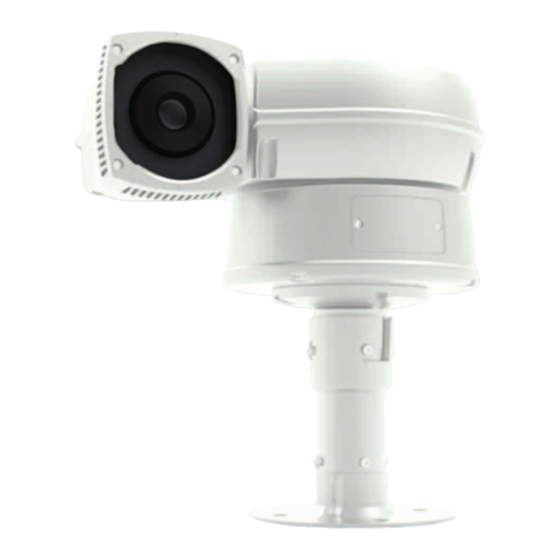
- Page 4 Part Names Part Names ZT-PTS SERIES ZT-PTS SERIES A. Basic Parts B. Connection Method CAMERA MAIN BODY BASE BODY ⓐ Explanation ⓑ Color BLACK Video Cable ⓐ ⓑ Explanation ⓒ DIP SWITCH COVER Color MOUNT HOLE (M4 x 16 - 4EA)
-
Page 5: Ceiling Mount Bracket
Installation Installation ZT-PTS SERIES ZT-PTS SERIES A. Ceiling Mount Bracket A-4. When you want to connect the cables from the inside of ceiling, pass the cables through the ceiling. When you want to connect the cables from the CONTENTS outside of ceiling, remove the hole cap from the side of the bracket and pass the cables through the hole. -
Page 6: Pole Stand
Installation Installation ZT-PTS SERIES ZT-PTS SERIES B. Pole Stand B-4. Install 4 pieces of Anchor bolt in the Ø13 holes at the edge and connect the cables. CONTENTS 1. POLE STAND 5. SCREW M4 x 16 2. BOLT & NUT M10 6. -
Page 7: Wall Mount Bracket
Installation Installation ZT-PTS SERIES ZT-PTS SERIES C. Wall Mount Bracket C-3. Connect the Safety wire of the Camera to the Bracket. In order to avoid getting entangled in the Camera, fasten the Safety wire to the bracket with CONTENTS Cable tie. (FIG.13) 1. -
Page 8: Quick Operating Keys
Quick Operating Keys Quick Operating Keys ZT-PTS SERIES ZT-PTS SERIES The Camera supports Pelco D/P Protocols • 65 + Preset The default setting of the Camera is Pelco D/P(Auto Detection) with 2400bps Preset Status is displayed, to remove this screen, Press Focus Near button. -
Page 9: Diagnostic
Diagnostic OSD Menu Setting ZT-PTS SERIES ZT-PTS SERIES Whenever the IR Camera is power on, a standard diagnostic is operated. A. OSD Menu Table MAIN MENU DOME SET DOME SET DOME SETUP CAMERA ID : CAM 1 [SYSTEM SET] CAMERA SET... -
Page 10: Dome Set
OSD Menu Setting OSD Menu Setting ZT-PTS SERIES ZT-PTS SERIES To enter OSD Menu, press the button 95+Preset then OSD Main Menu is - Set time : 15~90 (Each 5) displayed. - Set article : [AUTO] - RECOVER operation. [PRST1]-[PRST8] – PRESET1 ~ PRESET8 OPERATION. - Page 11 OSD Menu Setting OSD Menu Setting ZT-PTS SERIES ZT-PTS SERIES B-6-1. DOME SET - [NEXT PAGE] -SYSTEM SET Enter any number from 001~255 on the password blank area and again on To enter system set, use the joystick right to move when cursor on system set.
- Page 12 OSD Menu Setting OSD Menu Setting ZT-PTS SERIES ZT-PTS SERIES [SYSTEM STATUS] LOAD OPTIMIZED DEFAULT NOW EEPROM ALL DATA PROTOCOL : PELCO D/P ARE YOU SURE? YES NO CHECKING INITIALIZING BAUD RATE : 2400BPS FIRMWARE VER : 1.10a UPGRADEDDATE : 02.01.12...
-
Page 13: Camera Set
OSD Menu Setting OSD Menu Setting ZT-PTS SERIES ZT-PTS SERIES C. Camera Set D. Preset Set CAMERA SET PRESET SET COLOR MODE : B/W PRESET NO : 01 INVERS MODE : OFF PRESET ID : PRESET 01 D-ZOOM : OFF PAN : XXX.X... -
Page 14: Auto Scan Set
OSD Menu Setting OSD Menu Setting ZT-PTS SERIES ZT-PTS SERIES E. Auto Scan Set F. Tour Set 66+Preset button is working as AUTO SCAN after setting. 8 Programmable tours can be set and each tour can have up to 64 preset steps. -
Page 15: Pattern Set
OSD Menu Setting OSD Menu Setting ZT-PTS SERIES ZT-PTS SERIES G. Pattern Set H. Alarm Set 8 Programmable patterns are available with 16 characters of title. 4 Alarm inputs are available and each alarm is activating to presets, group tours After set the data to the each pattern #1 ~ 8, 81 ~ 88+preset buttons are working or patterns. -
Page 16: Sector Set
OSD Menu Setting DIP Switch Setting ZT-PTS SERIES ZT-PTS SERIES I. Sector Set A. ID Setting Up to 8 programmable sectors are available with 16 characters. The camera has camera ID to be controlled by controller or DVR. This feature is useful to memory the certain location such as parking zone or so on. - Page 17 DIP Switch Setting DIP Switch Setting ZT-PTS SERIES ZT-PTS SERIES SW1-#1 SW1-#2 SW1-#3 SW1-#4 SW1-#5 SW1-#6 SW1-#7 SW1-#8 SW1-#1 SW1-#2 SW1-#3 SW1-#4 SW1-#5 SW1-#6 SW1-#7 SW1-#8...
- Page 18 DIP Switch Setting DIP Switch Setting ZT-PTS SERIES ZT-PTS SERIES SW1-#1 SW1-#2 SW1-#3 SW1-#4 SW1-#5 SW1-#6 SW1-#7 SW1-#8 SW1-#1 SW1-#2 SW1-#3 SW1-#4 SW1-#5 SW1-#6 SW1-#7 SW1-#8...
- Page 19 DIP Switch Setting DIP Switch Setting ZT-PTS SERIES ZT-PTS SERIES B. 485 Termenation SW1-#1 SW1-#2 SW1-#3 SW1-#4 SW1-#5 SW1-#6 SW1-#7 SW1-#8 The 8 of DIP SW2 is used for 100Ω termination. Set ON DIP SW2-1st of only the last looped camera from the controller.
- Page 20 Trouble Shooting Specification ZT-PTS SERIES ZT-PTS SERIES If you have trouble operating in your camera, refer to the fallowing. THERMAL MODULE SENSOR Problem Solution Thermal Sensor Uncooled Micro Bolometer Pixel Pitch 25µm / 384 x 288 • Check if the power supply is DC 12V ~ 24V or AC 24V.
- Page 21 Dimension Memo ZT-PTS SERIES ZT-PTS SERIES...
- Page 22 Memo Memo ZT-PTS SERIES ZT-PTS SERIES...
Need help?
Do you have a question about the ZT-PTS Series and is the answer not in the manual?
Questions and answers