
Related Manuals for Fametech POS-8017F Series


Summary of Contents for Fametech POS-8017F Series
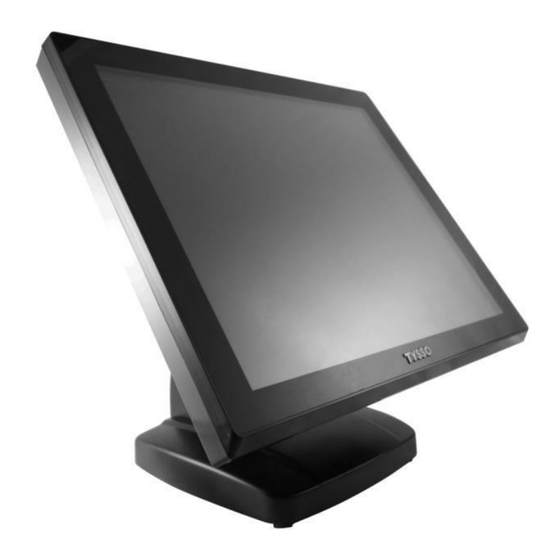
- Page 1 POS-8017F Series Full-Flat Touch Screen POS Terminals User Manual POS-8017F-i Ver. 1.7 © Copyright Fametech Inc. (TYSSO), 2016...
-
Page 2: Disclaimer
The information in this manual is subject to change without notice due to rapid improvement on IT technology. Users can get the most up to date information from our web sites: http://www.fametech.com.tw DISCLAIMER This manual has been examined for accuracy. While precaution has been taken in the... -
Page 3: Caution
Warranty does not cover any damage caused by improper use. TRADE MARKS AND SERVICE MARKS TYSSO is a registered trademark of FAMETECH INC. Other brand and product names are trademarks and registered trademarks and service marks of their respective owners. -
Page 4: Important Safety Information
IMPORTANT SAFETY INFORMATION Read following instructions carefully. Use only parts, especially power adapter, recommended by the manufacturer; unapproved parts may be hazardous. Before plugging the power cord into the AC inlet of the power supply unit, make sure that the voltage applied to the power outlet is within the specified range (100V ~240V). -
Page 5: Table Of Contents
Contents General Information ....................... i ABOUT THIS MANUAL ......................i DISCLAIMER ........................i WARNING ..........................i CAUTION ..........................ii WARRANTY LIMITS ......................ii TRADE MARKS AND SERVICE MARKS ................ii IMPORTANT SAFETY INFORMATION ................... iii 1. Product Overview ....................1 1.1. - Page 6 3.4. Boot .......................... 52 3.5. Security ........................54 3.6. Save & Exit ....................... 55 3.7. Updating the BIOS ....................56 4. Install the Drivers of POS Terminal ................ 58 4.1. Microsoft .NET Framework 3.5 (for Windows XP only) ..........60 4.2.
-
Page 8: Product Overview
1. Product Overview 1.1. Packing POS Terminal AC Power Cord Contents POS Terminal x 1 Power Adapter x 1 AC Power Cord x 1 RJ-45 to RS-232-DB9 Male Cable x 1 Optional Accessories Magnetic Stripe Card Reader (MSR)/i-Button Module ... -
Page 9: Specifications
1.2. Specifications Model POS-8017F-i Main Board Intel® Core™ i7 3630QM , 2.4GHz (6M Cache, up to 3.40 GHz) Intel® Core™ i5 3320M , 2.6GHz (3M Cache, up to 3.30 GHz) Intel® Core™ i3 3120M , 2.5GHz (3M Cache, 2.50 GHz) Intel®... - Page 10 Optional Peripherals 3 Track, PS/2 or USB or COM MSR/i-Button Module Dallas Key RS232 I/F Vacuum Fluorescent Customer Display Customer Display (700 cd/m2, 20 characters x 2 Lines) 8” or 10.4” LCD Display, with or without Touch 2nd Display Wi-Fi USB interface Module with Antenna For more information relating to the other optional peripherals, please contact the local representatives or technical support personnel of the providers.
- Page 11 Dimensions Left View Front View Right View Rear View Bottom View - 4 -...
-
Page 12: Parts Descriptions
1.3. Parts Descriptions Front View Touch Screen MSR/i-Button Module (Optional) Base Power Indicator Rear View HDD Cover MSR/i-Button Module Side I/O Ports (Optional) Base Rear Cover - 5 -... - Page 13 Side View MSR/i-Button Side I/O Ports Module (PS/2 Keyboard) (Optional) (PS/2 Mouse) (2 x USB Ports) Power Switch Left View Right View Bottom View (POS Unit) Bottom I/O Ports Bottom View (Base) Power Adaptor - 6 -...
-
Page 14: Bottom I/O Ports
1.4. Bottom I/O Ports Cash Drawer COM Port (RJ-11) (COM 6) 12VDC Power Output CFast Slot MIC In Input LINE COM Ports LAN Port COM Port (COM 4) (COM 1/COM 2) (RJ-45) PS/2 RJ-45 to RS-232-DB9 Male Cable (COM-6) CAUTION: The optional RJ-45 to RS-232-DB9 Male Cable can be connected to COM 6 ONLY. - Page 15 I/O Port Descriptions I/O Port Description Connect devices with USB connectors. There are 6 external USB ports available, (4 locate on the bottom and 2 left side ports). 2 x USB 3.0 (located on the bottom). 4 x USB 2.0 (2 located on the bottom and 2 on the left side). 1 x PS/2 connector for keyboard 1 x PS/2 connector for mouse PS/2...
-
Page 16: Pos Installation
2. POS Installation 2.1. Unpack Your POS The contents may vary with different options. If there’s any physical damage or missing parts, please contact your supplier immediately. Please keep all packing materials in case you need to ship back the device for service. Unpacking... -
Page 17: Install Your Pos System
2.2. Install Your POS System The product is a fully integrated POS System and easy for installation. To install the POS System: Place the product on the location. Plug the AC power cord to the POS system Connect the optional peripherals to the POS (for example: Mouse, Keyboard, and Barcode Scanner.) Plug the AC power cord to the power source (for example: electrical outlet). -
Page 18: Plug Ac Power Cord To The Pos
2.3. Plug AC Power Cord to the POS a. Remove the base cover from the base of the POS system. Base Cover b. The power adapter is installed on the bottom of the base (as image left illustrated). Power Adaptor Plug the supplied AC power cord into the power adaptor. -
Page 19: Install The Rear Top Mount Customer Display (Optional)
2.4. Install the Rear Top Mount Customer Display (Optional) Remove the base cover and two hinge covers from the base. Hinge Cover There are 2 securing holes for installing the Customer Display Hinge Cover Base Cover Securing Screws Tilt the POS unit properly so as to install the customer display. - Page 20 Now you can tilt the customer display to the angle desired and ready for use Note: The rear top mount customer display is an Optional Accessory and is not included in the standard package. Please contact your local representative for further information relating to purchase or technical supports.
-
Page 21: Replace Hard Disk
2.5. Replace Hard Disk a. Turn Off the POS unit. Unplug the cables on the POS unit. b. Remove the two hinge covers from the base. Hinge Cover Hinge Cover - 14 -... - Page 22 c. Loosen the securing screws on the VESA bracket. Carefully detach the POS unit from the base. d. Carefully place the POS unit to a flat and stable location (for example: table). Securing Note: Screw Please remove the object on the surface. Place a clean and soft cloths on the flat surface before placing the POS unit e.
- Page 23 Disconnect the HDD Cables to remove the HDD Module. HDD Module HEX Spacer g. Loosen the Threaded Hex Spacer of HDD Bracket and remove HDD Module from the POS unit. HDD Cables Replace the Hard Disk Securing Screws a. Loosen the securing screws to remove the hard disk from the bracket.
-
Page 24: Bios Setup Information
3. BIOS Setup Information The product is compatible with POS Ready, Windows Families (98/2000/XP/7) and Ubuntu Linux. If the drivers are required, find the necessary files from TYSSO official website.. Note. The BIOS configuration is for reference only, it may subject to change/update without prior notice. -
Page 25: Overview
Overview The BIOS is a program that takes care of the basic level of communication between the CPU and peripherals. It contains codes for various advanced features found in this system board. The BIOS allows you to configure the system and save the configuration in a battery-backed CMOS so that the data retains even when the power is off. -
Page 26: Default Configuration
Default Configuration Most of the configuration settings are either predefined according to the Load Optimal Defaults settings which are stored in the BIOS or are automatically detected and configured without requiring any actions. There are a few settings that you may need to change depending on your system configuration. - Page 27 BIOS MENU Key Function Keys Function Right and Left arrows Moves the highlight left or right to select a menu. Moves the highlight up or down between submenu and Up and Down arrows fields. <Esc> Exit to the BIOS Setup Utility. Scrolls forward through the values or options of the (plus key) highlighted field.
-
Page 28: Main
3.1. Main The Main menu is the first screen that you will see when you enter the BIOS Setup Utility System Date The date format is <day>, <month>, <date>, <year>. <Day> displays a week day, from Sunday to Saturday. <Month>... -
Page 29: Advanced
3.2. Advanced The Advanced menu allows you to configure your system for basic operation. Some entries are defaults required by the system board, while others, if enabled, will improve the performance of your system or let you set some features according to your preference. -
Page 30: Acpi Settings
3.2.1. ACPI Settings This section is used to configure the ACPI settings. Enable ACPI Auto Configuration Enable or disable the BIOS ACPI auto configuration. ACPI Sleep State Selects the highest ACPI sleep state the system will enter when the Suspend button is pressed. -
Page 31: Pc Health Status
When enabled, the system uses the RTC to generate a wakeup event. 3.2.2. PC Health Status This section displays the SIO hardware health monitor. Move the cursor to “PC Health Status” and press <Enter> key to access the submenu. - 24 -... - Page 32 Smart Fan Function This field configures the smart fan function. CPU Smart Fan Control Enable or disable the CPU Smart Fan. Boundary Enter the boundary value. The range is 0-127. Speed Count Enter the value of the speed count. The range is 1-100.
-
Page 33: Cpu Configuration
3.2.3. CPU Configuration This section is used to configure the CPU. It will also display the detected CPU information. Hyper-threading Enable this field for Windows XP and Linux which are optimized for Hyper-Threading technology. Select disabled for other OS not optimized for Hyper-Threading technology. -
Page 34: Sata Configuration
capabilities provided by Vander pool Technology. 3.2.4. SATA Configuration This section is used to set the options of SATA device. SATA Controller(s) This field is used to enable or disable the Serial ATA channels. SATA Mode Selection This field is used to determine how SATA controller(s) operates. IDE Mode This option configures the Serial ATA drives as Parallel ATA storage devices. - Page 35 When selecting the AHCI mode in the SATA Mode Selection, it will display the following information: - 28 -...
- Page 36 When selecting the AHCI mode in the RAID Mode Selection, it will display the following information: Alternate ID Report the alternate device ID. Port 0, Port 1 and Port 3 Enable or disable the serial ATA port. Hot Plug ...
-
Page 37: Amt Configuration
3.2.5. AMT Configuration This section configures the parameters of Active Management Technology. Intel AMT Enables or disables the AMT function. Un-Configure ME OEM Flag Bit 15: Un-configure ME without the password Disable ME Set ME disabled to the Soft Technology. - 30 -... -
Page 38: Usb Configuration
3.2.6. USB Configuration This section is used to configure USB parameters. Legacy USB Support Enabled Enable legacy USB. Auto Disables support for legacy when no USB devices are connected. Disabled Keep USB devices available only for EFI applications. EHCI Hand-off ... -
Page 39: F71889 Super Io Configuration
3.2.7. F71889 Super IO Configuration This section is used to configure the I/O functions supported by the onboard Super I/O chip. Restore AC Power Loss Power Off When power returns after an AC power failure, the system’s power is off. You must press the Power button to power-on the system. - Page 40 Serial Port 1 Configuration to Serial Port 2 Configuration Serial Port Enable or disable the serial port. Change Settings Select the IO/IRQ setting for the super I/O device. Device Mode - 33 -...
- Page 41 Change the serial port mode. Select the “High Speed“ or “Normal Mode“. Parallel Port Configuration (Reserved) Note: The Parallel port is only avail for the customized version mainboard (with parallel port connector mounted). For specific applications that require the parallel port, please consult the trained personnel prior to the configuration.
-
Page 42: Second Super Io Configuration
3.2.8. Second Super IO Configuration This section is used to configure the I/O functions supported by the onboard Super I/O chip. - 35 -... - Page 43 Serial Port 3 to Serial Port 6 Configurations Port 3 Port 4 - 36 -...
- Page 44 Port 5 Port 6 Serial Port Enable or disable the serial port. Change Settings Select the IO/IRQ setting for the super I/O device. Device Mode - 37 -...
-
Page 45: Network Stack
Change the serial port mode. Select either the “High Speed “or “Normal Mode“. 3.2.9. Network Stack This section configures settings relevant to the network stack. - 38 -... - Page 46 Network Stack Enable or disable UEFI network stack. Ipv4 PXE Support When select [Enabled], Ipv4 PXE boot supports. When select [Disabled], Ipv4 PXE boot option will not be created. Ipv6 PXE Support When select [Enabled], Ipv6 PXE boot supports. When select [Disabled], Ipv6 PXE boot option will not be created.
-
Page 47: Cpu Ppm Configuration
3.2.10. CPU PPM Configuration EIST This field is used to enable or disable the Intel Enhanced Speed Step Technology. CPU C3 Report Enabled/Disabled CPU C3 (ACPI C2) report to OS. CPU C6 Report Enabled/Disabled CPU C6 (ACPI C3) report to OS. ACPI T State ... -
Page 48: Serial Port Control
3.2.11. Serial Port Control This section is used to select the power of serial COM ports. COM 1, COM 2, COM 4 and COM 6 Select Select the power voltage of serial COM ports: 5V, 12V or RI. - 41 -... -
Page 49: Backlight Control
3.2.12. Backlight Control This section is used to select the lightness of backlight. Backlight Step1 is the darkest level. Step8 is the brightest level. - 42 -... -
Page 50: Chipset
3.3. Chipset This field is used to configure the functions of relevant chipset. - 43 -... -
Page 51: Pch-Io Configuration
3.3.1. PCH-IO Configuration Wake on LAN Enable this field to wake up the system via the onboard LAN or via a LAN card that supports the function of remote wake up. After G3 Select the state of AC power when the power is re-applied after a power failure. Power Off / WOL Power-on the system via WOL after G3. - Page 52 PCI Express Configuration PCI Express Root Port 1 to PCI Express Root Port 3 Control the PCI Express Root Port 1 ~ Port 3. - 45 -...
- Page 53 USB Configuration This field is used to configure the USB settings. XHCI Pre-Boot Driver Enable or disable the support for XHCI Pre-Boot Driver. XHCI Mode Select the mode to operate the XHCI controller. EHCI 1 and EHCI 2 EHCI 1 and EHCI 2 control the USB EHCI (USB 2.0) functions. One of them must always be enabled.
- Page 54 PCH Azalia Configuration This section is to configure the PCH Azalia settings. Azalia Select the control detection of the Azalia device. The options are [Disabled], [Enabled] and [Auto]. - 47 -...
-
Page 55: System Agent (Sa) Configuration
3.3.2. System Agent (SA) Configuration - 48 -... - Page 56 Graphics Configuration This field configures the graphics settings. Primary Display Auto: When the system boots, it will auto detects the display device. IGFX: When the system boots, it will first initialize the onboard VGA. DVMT Total Gfx Mem This field is used to select the DVMT5.0 total graphics memory size used by the Internet Graphics device.
- Page 57 LCD Control This field configures the parameters relating to the LCD Display. Primary IGFX Boot Display and Secondary IGFX Boot Display The options are VBIOS Default, CRT, and LVDS. LCD Panel Type This field is used to select the type of LCD panel used by the - 50 -...
- Page 58 internal graphics device. 1024x768 18bit for 15’’ LED Type Panel Type 3: 1024x768 24bit for 15’’ CCFL Type Panel Type 12: 1280x1024 48bit for 17’’ CCFL Type Panel Type 13: Spread Spectrum Clock Chip This field is used to select the clock control of spread. Hardware Spread is controlled by chip.
-
Page 59: Boot
3.4. Boot Setup Prompt Timeout Select the number of seconds to wait for the setup activation key. 65535(0xFFFF) denotes indefinite waiting. Bootup NumLock State This allows you to determine the default state of the numeric keypad. By default, the system boots up with NumLock on wherein the function of the numeric keypad is the number keys. - Page 60 keys. Quiet Boot Enable or disables the quiet boot function. Fast Boot Enable or disable boot with initialization of a minimal set of devices required to launch active boot option. Has no effect for BBS boot options. Skip VGA When it is enabled, BIOS will skip EFI VGA driver. Skip USB When it is enabled, USB devices will not be available after OS boot.
-
Page 61: Security
3.5. Security Administrator Password Set the administrator password. User Password Set the user password. - 54 -... -
Page 62: Save & Exit
3.6. Save & Exit Save Changes and Reset To save the changes, select this field and then press <Enter>. A dialog box will appear. Select “Yes” to reset the system after saving all changes made. Discard Changes and Reset ... -
Page 63: Updating The Bios
Restore Defaults To restore and load the optimized default values, select this field and then press <Enter>. A dialog box will appear. Select “Yes” to restore the default values of all the setup options. Save as User Defaults To save changes done so far as user defaults, select this field and then press <Enter>. - Page 64 - 57 -...
-
Page 65: Install The Drivers Of Pos Terminal
4. Install the Drivers of POS Terminal Please download the latest driver from TYSSO official website. Extract the compressed file and open the folder to install the driver(s). Double click the folder “Driver & Utility” to access the folder. There are categorized folders for POS Terminal, Peripherals and Touch Screen drivers. To install the drivers of POS terminal: Double click the folder “POS Terminal Driver”... - Page 66 There are subfolder of drivers and utilities for the operating system. User may double-click the icon “Setup” to initiate the Menu and install the appropriate drivers or utilities Move the cursor to the Utility Menu and click to install the software required ※...
-
Page 67: Microsoft .Net Framework 3.5 (For Windows Xp Only)
4.1. Microsoft .NET Framework 3.5 (for Windows XP only) Click “Microsoft .NET Framework 3.5” on the utility menu. Note: Before installing Microsoft .NET Framework 3.5, make sure you have updated your Windows XP operating system to Service Pack 3. There is application software or peripherals/optional devices require the different version of Microsoft .Net Framework. - Page 68 Setup is now installing the driver Setup completed. Click Exit to close the program. - 61 -...
-
Page 69: Intel Chipset Software Installation Utility
4.2. Intel Chipset Software Installation Utility The Intel Chipset Software Installation Utility is used for updating Windows® INF files so that the Intel chipset can be recognized and configured properly in the system. To install the utility, click “Intel Chipset Software Installation Utility” on the menu. Setup is ready to install the utility. - Page 70 Readme file information (for more installation tips). Click “Next” to continue or click “Cancel” to abort the installation. Setup is completed. It’s recommended to restart the system after the driver is installed. Click “Finish” to restart the computer. - 63 -...
-
Page 71: Intel Hd Graphics Driver
4.3. Intel HD Graphics Driver To install the driver, click “Intel HD Graphics Drivers” on the utility menu. Setup is now ready to install the graphics driver. Click Next tip continue. By default, the “Automatically run WinSAT and enable the Windows Aero desktop theme” is enabled. - Page 72 License agreement. Click “Yes” to continue. Readme File Information. Go through the readme document for system requirements and installation tips then click “Next” to continue. - 65 -...
- Page 73 Setup is now installing the driver. Click “Next” to continue. Click “Yes, I want to restart this computer now” then click “Finish” to complete the installation. Restart the system and then the new software installation will take effect. - 66 -...
-
Page 74: Lan Driver
4.4. LAN Driver To install the driver, click “Realtek LAN Drivers” on the menu. Click “Next” to start installing the driver to the computer. Click “Install” to continue the setting process - 67 -... - Page 75 Click “Finish” to finish the installation - 68 -...
-
Page 76: Audio Driver
4.5. Audio Driver Click “Next” to start installing the driver to the computer. The audio driver is successfully installed. It’s recommended to restart the system after the driver is installed. Click “Yes, I want to restart my computer now” then click “Finish” to restart the computer. Restarting the system will allow the new software installation to take effect. -
Page 77: Install The Touch Screen Driver
5. Install the Touch Screen Driver Please download the latest driver from TYSSO official website. Extract the compressed file and open the folder to install the driver(s). Double click the folder “Driver & Utility” to access the folder. There are categorized folders for POS Terminal, Peripherals and Touch Screen drivers. - 70 -... -
Page 78: Install The Driver Of Resistive Type Touch Panel
5.1. Install the Driver of Resistive Type Touch Panel To install the drivers of Resistive Touch Panel: Double click the folder “Touch Driver” to access the subfolder. There are drivers of Resistive type and Projective Capacitive type touch screen. To install the driver for Resistive type, select (double click) the folder “Resistive Touch”... - Page 79 Double click the file “Setup.EXE” to start the installation. Click “Next” to start the installation. - 72 -...
- Page 80 License Agreement. Click “I accept the terms of the license agreement” and click “Next” to continue. Setup Type: PS/2 Interface (reserved). This is reserved for Extra PS/2 Interface version only. Leave the check box UNMARKED. Click “Next” to continue. - 73 -...
- Page 81 Setup Type: RS-232 Interface (reserved): This is reserved for RS-232 Interface version only. Leave the check box UNMARKED. Click “Next” to continue. Setup Type: Calibration after system reboot: Click the checkbox “None” and click “Next” to continue. - 74 -...
- Page 82 There is a pop-up dialogue. Click “Ok” to continue. m. Setup Type: Support Multi-monitor System: Click the checkbox “Support Multi-Monitor System” and click “Next” to continue. - 75 -...
- Page 83 Choose Destination Location: Click “Browse to change the different destination folder. Note: It’s recommended to use the defined location and install the driver. Click “Next” to continue. Select Program Folder: Use the pre-defined setting and click “Next” to continue. - 76 -...
- Page 84 Create Shortcut on the desktop: Click the checkbox and click “Next” to continue. Now the software is installing to the system. - 77 -...
- Page 85 4-Point Calibration. Click “Yes” to perform touch screen calibration. Touch the first calibration mark on the edge of the screen. There is a beep sound to indicate the point is calibrated. Proceed to the next mark and perform all 4 calibration points to complete the calibration. Installation completed.
-
Page 86: Touch Screen Calibration (Resistive Type)
5.2. Touch Screen Calibration (Resistive Type) After the driver is installed to the system, there is a shortcut on the desktop for touch screen Calibration. User can re-configure the touch screen by initiating the utility. To calibrate the touch screen: Double click the icon to access the utility. - Page 87 Tap the calibration mark on the bottom-left to complete the first calibration point. There is a beep sound to indicate the point is calibrated. Proceed to the next mark and complete all calibration points The calibration is completed; Click “OK” to continue. - 80 -...
- Page 88 Tips: Advanced 9-point/25-point Calibration There are advanced 9-point calibration and 25-point calibration for more accurate calibration demands. Access “Setting” submenu, and select “Linearization Style” (9 Points or 25 Points) to calibrate your touch screen. - 81 -...
- Page 89 Access “Tools” submenu, and select “Linearization” to calibrate your touch screen. Tap the calibration mark on the bottom-left to complete the first calibration point. There is a beep sound to indicate the point is calibrated. Proceed to the next mark and complete all calibration points (9 Points or 25 Points). - 82 -...
-
Page 90: Peripherals Test
6. Peripherals Test The POS terminal is equipped with mainstream interfaces for the connection of peripherals and devices. If the POS is equipped with optional peripherals (for example: Wi-Fi module, magnetic stripe card reader, customer display, or a cash drawer). Please install the driver or perform the tests prior or to the POS system is operational. -
Page 91: Install The Wi-Fi Driver (Optional)
6.1. Install the Wi-Fi Driver (Optional) There are categorized subfolders for POS Peripherals. Select “WiFi” to access the subfolders. Open the folder “LR802UKN3(USB)”to access the subfolders: Open the folder to find the appropriate driver. Access the subfolder and double click the icon to install the driver. Click “Yes”... - Page 92 Select “Install driver only” and click “Next” to continue. Click “Install” to begin Installation. - 85 -...
- Page 93 The Wi-Fi driver is successfully installed. Click “Finish” to complete and exit the Wizard Note: To access the wireless network and initiate the connection, please refer to the service provider for further information. - 86 -...
-
Page 94: Test Your Magnetic Stripe Card Reader(Msr) And I-Button Module
6.2. Test Your Magnetic Stripe Card Reader(MSR) and i-Button Module Execute Start Menu and activate Notepad (All Programs >> Accessories >>Notepad). MSR Test: Swipe a card through the reader and the information will be displayed on the window. i-Button Test: Attach the i-button to the reader and the information will be displayed on the window. -
Page 95: Test Your Customer Display
6.3. Test Your Customer Display There are categorized subfolders for POS Peripherals. Select (double click) the subfolder “Customer Display”. There are two folders for LCD type Customer Display (DSP) and Vacuum Fluorescent type Display (VFD). Select the folder by the Customer Display installed. Select the subfolder “Test Utility”. - Page 96 The Communications Window pops up and ready for test. Enter any keys on the window and the texts will display on the customer display The texts are displayed on the customer display. To terminate the program, click (X) to close the Communications Window. There is a pop up window for notice.
-
Page 97: Test Your Cash Drawer
6.4. Test Your Cash Drawer There are categorized subfolders for POS Peripherals. Select “Cash Drawer” to access the subfolders Select “Test Software” to access the subfolders. Open the folder “Core i”. . Double click the icon to initiate the test software. Click “Open Cash Drawer”... - Page 98 Note: Digital I/O Configuration Setting Pins for DIO Item GP00 (Pin54) SIO_OUT0 GP01 (Pin55) SIO_OUT1 GP25 (Pin51) SIO_IN0 - 91 -...
- Page 99 Programming Guide To program the F71889 configuration registers, the following configuration procedures must be followed in sequence: Enter the Extended Function Mode. Configure the configuration registers. Exit the Extended Function Mode. The configuration register is used to control the behavior of the corresponding devices. To configure the register, use the index port to select the index and then writing data port to alter the parameters.
- Page 100 Relative Registers GPIO Registers (CR06) GPIO Output Enable Register - Index F0h Name Default Description Reserved. Reserved. 0: GPIO6 is in input mode. GPIO6_OE 1: GPIO6 is in output mode. 0; GPIO5 is in input mode. GPIO5_OE 1: GPIO5 is in output mode 0;...
- Page 101 Multi-Function Select 1 Register----- Index 2Ah (Powered by VSB3V) Name Default Description GPIO06/BEEP/ALERT # function select 00: The pin function is ALERT#. GPIO06_SEl 2'b11 01: The pin function is BEEP. 10: Reserved. 11: The pin function is GPIO06. GPIO05/LED_VCC function select GPIO05_SEl 00: The pin function is LED_VCC.
- Page 102 GPIO Output Data Register. --- Index F1h Name Default Description Reserved. Reserved. 0: GPIO6 outputs 0 when in input mode. GPIO6_VAL 1: GPIO6 outputs 1 when in output mode. 0: GPIO5 outputs 0 when in input mode. GPIO5_VAL 1: GPIO5 outputs 1 when in output mode. 0: GPIO4 outputs 0 when in input mode.
- Page 103 GPIO2 Output Enable Register. --- Index D0h Name Default Description 0: GPIO27 is in input mode. GPIO27_OE. 1: GPIO27 is in output mode. 0: GPIO26 is in input mode. GPIO26_OE 1: GPIO26 is in output mode. 0; GPIO25 is in input mode. GPIO25_OE 1: GPIO25 is in output mode 0;...
- Page 104 GPIO2 Pin Status Register --- Index D2h Name Default Description GPI027_IN The pin status of BSUIN2/GPI027. GPI026_IN The pin status of BSUIN2/GPI026. GPI025_IN The pin status of BSUIN2/GPI025. GPI024_IN The pin status of GPIO24/FWH_DIS. GPI023_IN The pin status of GPIO23/SPI_MOSI. GPI022_IN The pin status of GPIO22/SPI_MISO.
- Page 105 Sample Code in C language Control of GP00 and GP01 #define AddrPort 0x2E #define DataPort 0x2F <Enter the Extended Function Mode> WriteByte(AddrPort, 0x87) WriteByte(AddrPort, 0x87) //Must write twice to entering Extended mode < Select Logic Device > WriteByte(AddrPort, 0x07) WriteByte(DataPort, 0x06) // Select logic device 06h <...
-
Page 106: Appendix
7. Appendix 7.1. I/O Port Extension (Optional COM Port / Parallel Port) There is a reserved COM port and Parallel Port in the POS unit and you can add extra COM port or Parallel Port for your POS unit. Standard Bottom I/O Ports Custom Model A: Optional COM Port... -
Page 107: Main Board Configuration
7.2. Main Board Configuration 7.2.1. Mainboard Technical Document The settings of the mainboard are factory preset values and need not adjust for most applications. Please reserve the settings, installation and maintenance to the qualified personnel only. - 100 -... -
Page 108: Com Ports Pin Assignment
7.2.2. COM Ports Pin Assignment External COM Ports Setting (COM 1/2/4/6) Configure the external serial ports in the Advanced menu of the BIOS Setup Utility (see “3.2.11Serial Port Control”). - 101 -... -
Page 109: Com 5 Jumper Setting (Jp19)
7.2.3. COM 5 Jumper Setting (JP19) - 102 -... -
Page 110: Cash Drawer Power Select (J2)
7.2.4. Cash Drawer Power Select (J2) - 103 -... -
Page 111: Jumper Location
7.2.5. Jumper Location - 104 -... -
Page 112: Jumper Settings
7.2.6. Jumper Settings - 105 -... - Page 113 20161225 - 106 -...
Need help?
Do you have a question about the POS-8017F Series and is the answer not in the manual?
Questions and answers