
Related Manuals for Fametech POS-6000 Series


Summary of Contents for Fametech POS-6000 Series
- Page 1 Service Manual POS-6000 Modular POS Terminal POS-6000-D2550 / POS-6000-i/POS-6000-B Version 1.1 © Copyright Fametech Inc. (TYSSO) 2015...
-
Page 2: Table Of Contents
Table of Contents Parts Description ................1 Examining Your System ................1 Exploded View ......................1 Parts Description ....................2 Main Board ......................4 System Disassembly ................. 9 Before You Start ..................9 Detach the Optional Peripherals .............. 10 Disconnect the Modular MSR/i-Button Module ..........10 Disconnect the Modular VFD Customer Display .......... - Page 3 Table of Figures Figure 1 Exploded View of the System ................... 1 Figure 2 Main board Layout- Front (POS-6000-D2550) ............5 Figure 3 Main board Layout- Front (POS-6000-i) ..............6 Figure 4 Main board Layout- Front (POS-6000-B) ..............7 Figure 5 Main board Layout- Back (POS-6000-B)..............8...
-
Page 4: I Parts Description
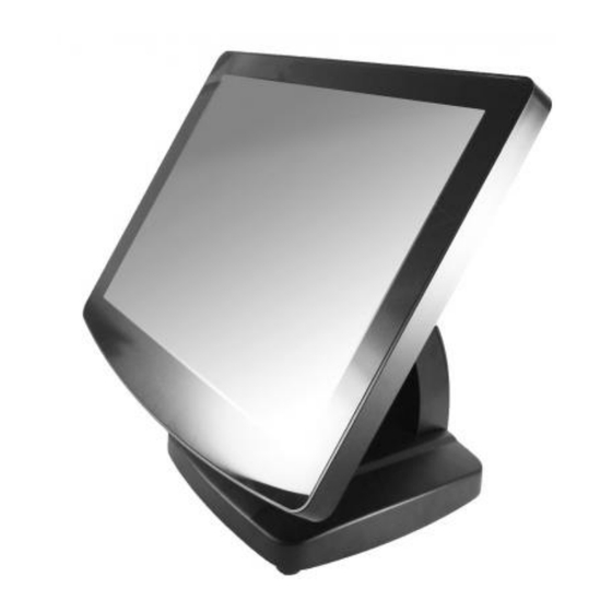
Parts Description Examining Your System Exploded View Figure 1 Exploded View of the System... -
Page 5: Parts Description
Parts Description Item Description Capacitive Touch Front Bezel Set (Black) Capacitive Touch Front Bezel Set (Silver) Front Bezel Resistive Touch Front Bezel Set (Black) Resistive Touch Front Bezel Set (Silver) Power Indicator LED Power Indicator Capacitive Touch Front Bezel Set-TYSSO LOGO (Black) Front Bezel Capacitive Touch Front Bezel Set-TYSSO LOGO (Silver) (TYSSO Logo) - Page 6 Item Description Rear Mount VFD Customer Display (Black) Rear Mount VFD Customer Display (Silver) Rear Mount VFD Customer Display - TYSSO LOGO (Black) Rear Mount VFD Customer Display - TYSSO LOGO (Silver) Customer Display Unit Rear Mount DSP Customer Display (Black) Rear Mount DSP Customer Display (Silver) Rear Mount DSP Customer Display - TYSSO LOGO (Black) Rear Mount DSP Customer Display - TYSSO LOGO (Silver)
-
Page 7: Main Board
Main Board ● Main Board Connection / Installation Notes The table below is the descriptions of the connectors of the main board. Each connector/slot is used for the specified part or optional peripheral. Please refer to the notes as below and examine the layouts of the main boards to locate the correct connectors so as to complete the installation. -
Page 8: Figure 2 Main Board Layout- Front (Pos-6000-D2550)
● POS-6000-D2550 Modular Customer Display Connector Connector (Reserved) Front View Figure 2 Main board Layout- Front (POS-6000-D2550) -
Page 9: Figure 3 Main Board Layout- Front (Pos-6000-I)
● POS-6000-i Modular Customer Display Connector Connector Front View Figure 3 Main board Layout- Front (POS-6000-i) -
Page 10: Figure 4 Main Board Layout- Front (Pos-6000-B)
● POS-6000-B Modular Customer Display Connector Connector Front View Figure 4 Main board Layout- Front (POS-6000-B) -
Page 11: Figure 5 Main Board Layout- Back (Pos-6000-B)
CFAST Slot Figure 5 Main board Layout- Back (POS-6000-B) -
Page 12: System Disassembly
System Disassembly Before You Start To prevent injuries to the LCD Panel, Carefully Place the POS on a flat, clean and stable surface (for example: a stable long table) Prepare additional cushioned material (for example: a soft, clean blanket). ... -
Page 13: B Detach The Optional Peripherals
Detach the Optional Peripherals There are some of the optional peripherals installed onto the POS system. Please detach the peripherals and restore to the secure location. Note: Please turn off the whole POS system and unplug the power cable from the electrical outlet. -
Page 14: Disconnect The Modular Vfd Customer Display
Disconnect the Modular VFD Customer Display There are two securing screws of the Modular VFD Customer Display. Use a screw driver to loosen the securing screws. Securing Screws of Modular VFD Customer Display Loosen the securing screw Pull the Module upward; there is a flat ribbon cable connected to the POS unit. -
Page 15: C Detach The Base From Pos Unit
Detach the Base from POS Unit Tilt the POS unit horizontally. Unplug the cables and connectors from the POS unit. Hinge Holder Covers Unplug the cables from the bottom I/O ports Remove the hinge holder covers according to the direction of the arrows Loosen the 3 screws and detach Remove the Hinge Holder Covers... -
Page 16: D Disassemble The Pos Unit
Disassemble the POS Unit Remove the HDD Module Place the POS unit on a flat, clean and stable location (desk, table…etc). Loosen the securing screw. The Securing Screw of HDD Cover Pull the HDD cover to the left and pull out the module. Disconnect the HDD cables to remove the HDD module. -
Page 17: Remove The Back Cover Of The Pos Unit
Remove the Back Cover of the POS Unit Loosen and remove the five M3x8 securing screws (as yellow marks illustrated) from the POS Unit. M3x8 Screw Loosen and remove the securing screws with spring from the POS unit (as red mark illustrated) Securing Screws of Back Cover M3x8 (yellow), Securing Screw with spring (red) -
Page 18: Remove The Hdd Cable
Remove the HDD Cable Disconnect the HDD cables from the Main Board. Remove the HDD Cable from the Main Board... -
Page 19: Remove The I/O Board Of Modular Msr/I-Button
Remove the I/O Board of Modular MSR/i-Button Tear off the sealing tapes. Side I/O Board connecting to the Main Board Unplug the I/O connectors from the Main Board. The 9-wire connector of RS-232 (up, reserved) And the 7-wire connector of USB port for modular MSR/i-Button (below ) Loosen the I/O Bracket Loosen the securing screws of... -
Page 20: Remove The Side I/O Board
Remove the Side I/O Board Unplug the I/O connector from the Main Board. Side I/O Board connecting to the Main Board Loosen the securing screws to remove the Side I/O board. Removed Side I/O Board Loosening the Securing Screws Disconnect the Inverter Disconnect the cable of LCD Panel to remove the inverter (as yellow mark indicated). -
Page 21: Disconnect The Touch Control Unit (Capacitive Type)
Disconnect the Touch Control Unit (Capacitive Type) Disconnect the cables of Touch Control Unit from the Main Board Disconnect the Touch Control Unit from Main Board Note: The Touch Control Unit is connected to the Touch Panel (as red arrow indicated). DO NOT disported or disassemble it from the touch panel. -
Page 22: Disconnect The Touch Control Unit (Resistive Type)
Disconnect the Touch Control Unit (Resistive Type) The Resistive Type Touch Control Unit is embedded in the Main Board. To disconnect the Resistive Type Touch Control Unit: Disconnect the connector of Touch Control Panel from the Main Board Disconnect the Touch Control Unit from Main Board Touch Control Unit Connector of the Main Board... -
Page 23: Disconnect The Lvds Cable From The Main Board
Disconnect the LVDS Cable from the Main Board Disconnect the LVDS cable from the Main Board LVDS Cable connected on the Main Board Disconnect the LVDS Cable from the Main Board Disconnect the Inverter Cable from the Main Board Disconnect the Inverter cable from the Main Board Inverter Cable on the Main Board The LVDS Cable is disconnected... -
Page 24: Disconnect The Connectors Of Speakers & Power Indicator
Disconnect the Connectors of Speakers & Power Indicator Disconnect the Power Indicator (blue-white twisted pair cable) from the Main Board. The Power Indicator Disconnect the Speaker (RED/Black (blue-white twisted pair cable) twisted pair cable) from the Main Speakers Board. (Red/Back twisted pair cable) -
Page 25: Remove The Main Board
m. Remove the Main Board Use a HEX screw driver to remove the hex mounting screws on the I/O bracket Remove all of the securing screws of the Main Board Main Board Slightly move the Main Board forward and you can take the Main Board out of Securing Screws of the Main Board the Unit Main Board... -
Page 26: Remove The Ram Module
Remove the RAM Module Release the latches on the two sides of the RAM module slot. The RAM Module would lift up to a degree (approximately 30° ). Gently slide the module out of the slot Repeat the step 1~2 to remove the other RAM Module... -
Page 27: Remove The Cpu Fan & Heat Sink (For Pos-6000-I Only)
Remove the CPU Fan & Heat Sink (for POS-6000-I only) Disconnect the CPU Fan connector. Turn over the Main Board and remove the securing screws (or latches) to release the CPU Fan & Heat Sink CPU Fan & Heat Sink (left) and Main Board (Right) Remove the I/O Bracket Loosen the 2 securing screws and then pull downward to remove the... -
Page 28: Remove The Speaker And Power Switch
Remove the Speaker and Power Switch 1. Loosen the securing screws of the speaker. Speaker 2. Loosen the latch and move the twisted pair cables of Power Switch and LED Indicator. 3. Remove the twisted pair cables of Power Switch on the Chassis Power Indicator from the hooks of Metal Chassis. -
Page 29: Remove The Lcd Panel Set
Remove the LCD Panel Set 1. Loosen the securing screws of the LCD Panel Chassis to remove the LCD Panel. Loosen the securing screw of Chassis Securing Screws of LCD Panel 2. Lift up the LCD Panel with Chassis from the Front Bezel (with Touch Panel) The LCD panel with chassis Front Bezel with Touch Panel... -
Page 30: Detach The Lcd Panel From Chassis
Detach the LCD Panel from Chassis There are two screws on both sides of the LCD Panel Set. Loosen the screws and then remove the chassis from the panel Securing Screws of the Chassis LCD Panel Chassis with LCD Panel Note: Store the removed LCD Panel on a secure location with proper protection. -
Page 31: Remove The Power Indicator From The Front Bezel Set
Remove the Power Indicator from the Front Bezel Set Pull the LED Power Indicator (black/white twisted pair cables) with care, and detach from the Front Bezel Set. Securing Screws of the Chassis Front Bezel Set with Touch Panel Warning: DO NOT DETACH the Front Bezel Set (with Touch Panel) Please purchase the whole Set for replacement. -
Page 32: Remove The Led Back Light Board (For Front Bezel Set With Tysso Logo Version Only)
Remove the LED Back light Board (for Front Bezel Set with TYSSO LOGO version ONLY) It the Front Bezel Set is with TYSSO LOGO. There is a LED Backlight Board on the Front Bezel. To replace the LED Board: Remove the LED board with care. Replace a new one on the Front Bezel LED Backlight Board on Front Bezel Set Remove the LED Board... -
Page 33: E Disassemble The Base Kit
Disassemble the Base Kit Remove the Power Adapter and Base Turn over the base and loosen the securing screws to remove the power adaptor. The Base with Adaptor Module Remove the screws from the Base. Disassemble the Base Arm from the Base Adaptor Module (Adaptor and holder) Loosen the securing screws to remove... -
Page 34: Disassemble The Base Arm Set
Disassemble the Base Arm Set Turn and remove the two swivels and then detach the Base Bracket from the Base Arm Set. Loosen the four securing screws of hinge to remove the base bracket from Base Arm Set Hinge Swivel Hinge Base Bracket Turn and remove the swivels from Base Arm Set... - Page 35 Revision History Date Version Note Description March. 15. 2015 Ver. 1.1 Add POS-6000-B Add J1900 Bay Trail Mainboard connection information. Dec. 20, 2014 Ver. 1.0 Preliminary version released...
Need help?
Do you have a question about the POS-6000 Series and is the answer not in the manual?
Questions and answers