Table of Contents
Advertisement
Quick Links
Download this manual
See also:
Service Manual
Advertisement
Table of Contents

Related Manuals for Fametech TP-2515


Summary of Contents for Fametech TP-2515
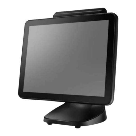
- Page 1 TP-2515 Fanless Full-Flat POS Terminal User Manual Installation Guide Ver. 1.0 © Copyright Fametech Inc. (TYSSO), 2018...
-
Page 2: Disclaimer
The information in this manual is subject to change without notice due to rapid improvement on IT technology. Users can get the most up to date information from our web sites: http://www.fametech.com.tw DISCLAIMER This manual has been examined for accuracy. While precaution has been taken in the... -
Page 3: Caution
Warranty does not cover any damage caused by improper use. TRADE MARKS AND SERVICE MARKS TYSSO is a registered trademark of FAMETECH INC. Other brand and product names are trademarks and registered trademarks and service marks of their respective owners. -
Page 4: Important Safety Information
IMPORTANT SAFETY INFORMATION Read following instructions carefully. Use only parts, especially power adapter, recommended by the manufacturer; unapproved parts may be hazardous. Before plugging the power cord into the AC inlet of the power supply unit, make sure that the ... -
Page 5: Table Of Contents
Contents General Information ....................... i ABOUT THIS MANUAL......................i DISCLAIMER ........................i WARNING ..........................i CAUTION ..........................ii WARRANTY LIMITS ......................ii TRADE MARKS AND SERVICE MARKS ................ii IMPORTANT SAFETY INFORMATION ................iii 1. Product Overview ....................1 1.1. Packing ........................1 1.2. -
Page 6: Product Overview
1. Product Overview 1.1. Packing POS Terminal Power Adapter* AC Power Cord Quick Installation Guide (installed on the Base) Contents POS Terminal Power Adapter (installed on the base) AC Power Cord Quick Installation Guide Optional Accessories ** ... -
Page 7: Specifications
1.2. Specifications Model TP-2515 Intel® Bay Trail-D Platform, Celeron® Processor J1900 2.0 GHz (2M Cache, up to 2.42 GHz) System Memory 1 x DDR3L SO-DIMM Socket, up to 8GB Graphic Intel® HD Graphics POS Ready 7, Windows 7, Windows 8.1,... - Page 8 Peripherals Optional Peripheral 9.7", 350nits and resolution up to 1024 x 768 2nd Display 15", 300nits and resolution up to 1024 x 768 Optional PCAP Touch supported Customer Display VFD, 20 Columns x 2 Lines Bi-directional, comply with ISO 7811 and Track 1/2/3 (HID USB) Bi-directional, comply with ISO 7811 and Track 1/2/3 (HID USB) Chip Card Read/write follow ISO7816 /EMV specification and...
- Page 9 Dimensions Top View Left View Front View Right View Rear View Bottom View Note: The Magnetic Stripe Card Reader (MSR) and i-Button Module are optional parts and may not be included in the package. Please purchase the optional parts separately. - 4 -...
-
Page 10: Parts Descriptions
1.3. Parts Descriptions Front View Touch Screen i-Button (Optional) (Optional) Power Indicator 2D Barcode Scanner Base Bottom View (Base, with AC Power Adapter) AC Power Cord Connector Base - 5 -... - Page 11 Rear View Customer Display (Optional) i-Button (Optional) (Optional) Power Switch Base Cable Access Opening Bottom I/O Ports - 6 -...
-
Page 12: I/O Ports Descriptions
1.4. I/O Ports Descriptions Main Power Input 12V DC COM 3 Cash Drawer USB Ports COM 4 COM 1 COM 2 (Optional) I/O Ports Descriptions: I/O Port Description Connect devices with USB type A connectors. USB Ports (3 x USB 2.0 and 1 x USB 3.0) 1 x 15 pin D-type connector serves to transmit VGA data to the monitor The DB9 female type serial ports with power output (selectable by BIOS) COM1 ~ COM 4:... -
Page 13: Pos Installation
2. POS Installation 2.1. Unpack Your POS The contents may vary with different options. If there’s any physical damage or missing parts, please contact your supplier immediately. Please keep all packing materials in case you need to ship back the device for service. ... -
Page 14: Install Your Pos
2.2. Install Your POS Electrical Outlet Power Cord POS Terminal Place the POS terminal on the proper location. Connect the power cord to the POS terminal. (The Power Adapter is pre-installed on the Base). Cable Access Opening Cable Access Opening Power Cord of the Base Connect the optional peripherals to the POS... - Page 15 Note: Always install the POS terminal and the optional peripherals on a flat, clean and stable location. To prevent obstruction on the operator, reserve appropriate space for the POS terminal and remove unnecessarily objects or items. - 10 -...
-
Page 16: Appendix
Appendix A. Install LM-2010-X Secondary (2nd) LCD Display (Optional) a. Remove the Protective Cover of the POS terminal. Top Cover Protective Cover LCD Display Remove the Top Cover of the 2nd LCD Display. c. Adjust the angle of the 2nd LCD Display horizontally. -
Page 17: Osd Control Button Of The Secondary (2Nd) Lcd Display
OSD Control Button of the Secondary (2nd) LCD Display The Control Buttons are located in the rear of the Secondary LCD Display. Press and pull downward to remove the back cover. Control Buttons Back Cover MENU LEFT / RIGHT ENTER LED Indicator POWER... -
Page 18: Install The Modular Customer Display (Optional)
B. Install the Modular Customer Display (Optional) Remove the Top Cover of the Customer Display. Remove the Protective Cover of the Top Cover POS terminal. Protective Cover Modular Customer Display There is a connector for the Modular Customer Display. Connector Top Cover Modular Adjust the Customer Display horizontally. -
Page 19: Install The Msr & I-Button Module (Optional)
C. Install the MSR & i-Button Module (Optional) To install the i-Button Module: a. Turn Off the POS Terminal. Remove the Protective Covers on the two sides of the POS terminal. Protective Protective Cover Cover b. Install the i-Button Module to the POS terminal. - Page 20 To Install the MSR Module: e. Install the MSR Module to the POS terminal. Note: Connect the connector of MSR to the connector of POS terminal. MSR Module (Back Cover Removed) Connect the connector of MSR to the POS terminal f.
-
Page 21: Replace The Hard Disk Drive Of Your Pos Terminal
D. Replace the Hard Disk Drive of Your POS Terminal There is a HDD drive slot on the side of the POS terminal. a. Remove the back cover of MSR (if installed). Remove the securing screws and disconnect the MSR from the POS terminal. Securing Screws Back Cover... - Page 22 TIP: Replace a New Hard Disk to the HDD Bracket Bracket 1. Loosen the securing screws to remove the Hard Disk hard disk from the bracket. Then replace a new hard disk. 2. Secure the new HDD to the bracket. Securing Screws 3.
Need help?
Do you have a question about the TP-2515 and is the answer not in the manual?
Questions and answers