
Related Manuals for Fametech Zircon Series


Summary of Contents for Fametech Zircon Series
- Page 1 Zircon Series All-in-One POS System User Manual POP-950-B Ver. 2.2 © Copyright Fametech Inc. (TYSSO), 2016...
-
Page 2: General Information
General Information ABOUT THIS MANUAL The purpose of this user’s manual is to provide general information on TYSSO Zircon Series (POP-950) POS System and to show the users how to configure the hardware-related configurations. The information in this manual is subject to change without notice due to rapid improvement on IT technology. -
Page 3: Caution
Warranty does not cover any damage caused by improper use. TRADE MARKS AND SERVICE MARKS TYSSO is a registered trademark of FAMETECH INC. Other brand and product names are trademarks and registered trademarks and service marks of their respective owners. -
Page 4: Important Safety Information
IMPORTANT SAFETY INFORMATION Read following instructions carefully. Use only parts, especially power adapter, recommended by the manufacturer; unapproved parts may be hazardous. Before plugging the power cord into the AC inlet of the power supply unit, make sure that the voltage applied to the power outlet is within the specified range (100V ~240V). -
Page 5: Table Of Contents
Contents General Information ......................i ABOUT THIS MANUAL ......................i DISCLAIMER ........................i WARNING ..........................i CAUTION ..........................ii WARRANTY LIMITS ......................ii TRADE MARKS AND SERVICE MARKS ................ii IMPORTANT SAFETY INFORMATION ................... iii 1. Product Overview ....................1 1.1. Items .......................... 1 1.2. - Page 6 3.2.9. IDE Configuration ......................55 3.2.10. Miscellaneous Configuration ..................56 3.2.11. PCI Subsystem Settings ....................57 3.2.12. Network Stack Configuration ..................61 3.2.13. CSM Configuration ....................... 62 3.2.14. USB Configuration ....................... 63 3.2.15. Security Configuration ....................64 3.3. Chipset ........................65 3.3.1.
-
Page 8: Product Overview
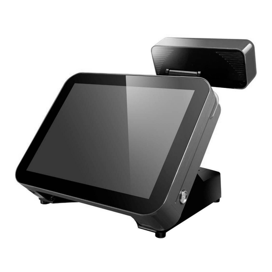
1. Product Overview 1.1. Items POS System AC Power Cord Packing List: POS Unit x 1 Power Adapter (Hidden under Base) x 1 AC Power Cord x 1 Optional Accessories Magnetic Stripe Card Reader (MSR) Thermal Receipt Unit ... -
Page 9: Specifications
1.2. Specifications Model POP-950-B Main Board Intel® Bay Trail-D Platform, Celeron® Processor J1900 (2.0 GHz, 2M Cache,) System Memory 1 x DDR3L SO-DIMM 1333MHz, up to 8 GB Graphic Intel® HD Graphics OS Support POS Ready 7, Windows 7, Windows 8, Windows 10, Linux Display Display Type 15"... - Page 10 Printer Unit (Optional) General Print Method Thermal line printing Print Speed 250mm/sec Print Life 100 Km ANK Font Font A: 12 x 24 dots Print Font Font B: 9 x 17 dots Chinese character: 24 x 24 dots Print Resolution 576 dots/line or 512 dots/line International Font, Big 5 Chinese, GB Chinese, Print Font Character Support...
- Page 11 Customer Display Unit (Optional) General Display Type Vacuum Fluorescent Display Brightness 700 cd/m2 Number of Columns 20 x 2 Character Size (mm) 6.4 x 9.2 (W x H), 5x7 dot matrix Command Set ESC/POS Font Character Support 96 Alphanumeric & 13 international Interface RS-232.
- Page 12 Dimensions Left View Front View Right View Right View (VFD Pole max. height) (VFD Pole min. height)
-
Page 13: Parts Description
1.3. Parts Description Front View Power Switch of Touch Screen Customer Display Power Switch Bottom I/O Cover Rear View Customer Display Receipt Slot Printer Cover Button HDD Cover Paper Feed Button Printer Cover Power Switch of Receipt Printer Unit... - Page 14 Bottom View Bottom I/O Cover AC Power Cord Connector I/O Ports for Printer Unit Side View Side PS/2 USB Ports i-Button Left View Right View...
-
Page 15: I/O Ports
1.4. I/O Ports Side I/O ports Bottom I/O ports Bottom I/O Cover Printer I/O ports Bottom I/O Ports Side I/O Ports Serial Port RJ-45 RJ-11 I/O Ports for Printer Unit * Printer Unit is an optional part and may not include in the product. - Page 16 I/O Ports Descriptions: I/O Port Description Connect devices with USB connectors KB+MS PS/2 connector for mouse or keyboard PWR IN 4 din rounded-power-jack for connecting an AC to DC +12V power adapter COM 1/2 support power RI/5/12V PWR COM refer to PWR COM Jumper Setting (as shown in the image below) CFAST 1 x CFAST slot...
-
Page 17: Components & Peripherals Installation
2. Components & Peripherals Installation 2.1. Unpack Your POS The contents may vary with different options. If there’s any physical damage or missing parts, please contact your supplier immediately. Please keep all packing materials in case you need to ship back the device for service. ... -
Page 18: Install Your Pos System
2.2. Install Your POS System The product is a fully integrated POS System and easy for installation. To install the POS System: Place the product on the location. Plug the AC power cord to the POS system Connect the optional peripherals to the POS (for example: Mouse, Keyboard, and Barcode Scanner.) Plug the AC power cord to the power source (for example: electrical outlet). -
Page 19: Replace The Hard Disk
2.3. Replace the Hard Disk Loosen the securing screw to remove the HDD cover Note: HDD Cover To prevent injuries to the LCD Panel, Carefully lay the front of the unit face down on a flat, clean and stable surface with additional cushioned material (for example: blanket). -
Page 20: Plug Ac Power Cord To The Pos System
2.4. Plug AC Power Cord to the POS System The power adapter should be found on the bottom of the base. Carefully lift up the POS and there is a power connector in the bottom (as image below illustrated). Note: To prevent injuries to the LCD Panel, Carefully lay the front of the unit face down on a flat, clean and stable surface with... -
Page 21: I/O Interface
2.5. I/O Interface You can install the peripherals (for example: mouse, keyboard, barcode scanner, or cash drawer) via the I/O interface of the POS system according to your request. To install the peripherals to the POS system: Pull the Bottom I/O cover and connect the optional peripherals to the POS system. -
Page 22: Install Your Receipt Printer (Optional)
2.6. Install Your Receipt Printer (Optional) The POP-950 has optional thermal receipt printer module that is pre-installed into the POS system. To install the paper roll into the printer: 2.6.1. Install/Replace the Paper Roll a. Press the button to open the printer cover. -
Page 23: Buttons & Indicators Of Receipt Printer Unit
2.6.2. Buttons & Indicators of Receipt Printer Unit Buttons Paper Feed: This function is to advance the Power Indicator paper. Error Indicator Paper Indicator Press the key and the paper Paper Feed Button advances by a single line. Press and hold the key for over 3 seconds and the paper Cover Release Button advances by multiple lines. -
Page 24: Dip Switch Configuration Of The Receipt Printer
2.6.3. Dip Switch Configuration of the Receipt Printer In general, the receipt printer unit is pre-installed on the POS system and need not change the settings. To change the setting of the printer, Please follow the steps as follows: a. Switch off the power and carefully lift up the POS system. - Page 25 DIP Switch Setting (DIP 1~ DIP 6) DIP Switch Function Paper Cutter Audio Alarm Yes (*) Print Density Dark Light (*) Two-byte Character Code Yes (*) Character Per Line 48 (*) Cutter with Cash Drawer No (*) 7 & 8 Baud Rate Setting OFF (*) The “*”...
-
Page 26: Virtual Serial Port Installation (For Usb Connection Only)
2.6.4. Virtual Serial Port Installation (for USB Connection Only) When connect the receipt printer to the computer with USB cable, turn on the computer and the system will found a new hardware automatically and then initiate the Found New Hardware Wizard automatically (as image below illustrated): RS-232 RJ-45 RJ-11 Printer Cable... - Page 27 Access the path: Driver & Utility\Peripherals\ Thermal Printer” Click “OK” to continue. Select the folder “PRP 650 & 950”. Browse the subfolder “Driver”. Access the subfolder “USB_Virtual_COM”. Access the subfolder corresponds to the version of operating system. Double-Click the icon to proceed.
- Page 28 Click “Next” to continue The driver of Virtual Serial Port is successfully installed. Click “Finish” to exit.
- Page 29 The Virtual COM port activates automatically when the printer is switched on. You can access “My Computer>>Proprieties>>Hardware>>Device Manager>> to examine the Virtual COM port Note: For USB (Virtual COM) Driver Installation Please install the Virtual COM driver before Printer driver installation. Select the proper Virtual COM port number when installing the Printer Unit driver.
-
Page 30: Install The Driver And Setup Of Receipt Printer Unit
2.6.5. Install the Driver and Setup of Receipt Printer Unit Please download the latest driver from TYSSO official website. Extract the compressed file and open the folder to install the driver(s). There are categorized folders for POS Terminal, Peripherals and Touch Screen drivers. Select “Peripherals”... - Page 31 Select the folder according to the system required. For Windows system, please select “Windows” Select “EXE” to install the driver Double-click the icon and follow the on-screen instructions to install the driver. The setup wizard of receipt printer driver. Click “Next” to continue.
- Page 32 Select the appropriate operating system for your POS. Click “Next” to continue. Module Type Setting: Select the printer model number using the menu below.
- Page 33 Default Printer Setting: To set the printer as the default printer, click the checkbox to confirm. Printer Port Setting: Select appropriate serial port (or Virtual COM port) according to your POS system preset setting. Click “Configure Port” ” to continue.
- Page 34 Configure Port: Select the Bit per second (Baud Rate) to 19200. Click “OK” to continue. Click “Install” to Start Installation.
- Page 35 m. Configuration Completed. Click “Finish” to exit the menu. Note: Reboot the HOST PC It’s recommended to reboot the HOST PC and proceed to the next step.
- Page 36 Examine the Port Setting: Remember to access the properties of your printer. Make sure the port of printer is correctly configured. Move the cursor to the printer and Right-Click the mouse button. There is a menu displayed on the printer. Click “Printer properties”...
- Page 37 Access sub menu “Ports”, and click to select the correct port for your printer. Click “Configure Port to examine the COM port setting.
- Page 38 Examine the parameters of selected COM port that fit to the settings of the printer Click “OK” to exit.
-
Page 39: Adjust The Customer Display (Optional)
2.7. Adjust the Customer Display (Optional) The POP-950 has optional Customer Display that is pre-installed into the POS system. To adjust the Angle of View: Pull the tube of the Customer Display to the desired height. Adjust the Display to the proper View Angle. -
Page 40: Bios Setup
3. BIOS Setup This motherboard supports a programmable firmware chip that you can update using the provided utility. Use the BIOS Setup program when you are installing a mother- board, reconfiguring your system, or prompted to “Run Setup.” This section explains how to configure your system using this utility. -
Page 41: Legend Box
LEGEND BOX The keys in the legend bar allow you to navigate through the various setup menus. Key(s) Function Description ← Select Screen ↑↓ Select Item Change Option / Field / Value Enter Go to Sub Screen PGDN Next Page PGUP Previous Page HOME... -
Page 42: Bios Menu Screen
BIOS Menu Screen When you enter the BIOS, the following screen appears. The BIOS menu screen displays the items that allow you to make changes to the system configuration. To access the menu items, press the up/down/right/left arrow key on the keyboard until the desired item is highlighted, then press [Enter] to open the specific menu. -
Page 43: Main Setup
3.1. Main Setup This menu gives you an overview of the general system specifications. The BIOS automatically detects the items in this menu. Use this menu for basic system configurations, such as time, date etc. □ System Date The date format is <Date>, <Month>, <Day>, <Year>. □... -
Page 44: Advanced Bios Setup
3.2. Advanced BIOS Setup Select the Advanced tab from the setup screen to enter the Advanced BIOS Setup screen. You can select any of the items in the left frame of the screen, such as Chipset configuration, to go to the sub menu for that item. You can display an Advanced BIOS Setup option by highlighting it using the <Arrow>... -
Page 45: Acpi Settings
3.2.1. ACPI Settings □ Enable Hibernation The item is used to enable or disable Enable Hibernation. □ ACPI Sleep State Selects the highest ACPI sleep state the system will enter when the SUSPEND button is pressed. Configuration Options: [Suspend Disable], [S1 (CPU Stop Clock)], [S3 (suspend to RAM)] □... -
Page 46: F81866 Super Io Configuration
3.2.2. F81866 Super IO Configuration □ Watch dog Timer The item is used to enable or disable watch dog. - Page 47 3.2.2.1. Serial Port 1 Configuration □ Serial Port The item is used to enable or disable the serial port. □ Device Settings The item is used to show the serial port IO port address and interrupt address. □ Change Settings The item is used to change COM address as required.
- Page 48 3.2.2.2. Serial Port 2 Configuration □ Serial Port The item is used to enable or disable the serial port. □ Device Settings The item is used to show the serial port IO port address and interrupt address. □ Change Settings The item is used to change COM address as required.
- Page 49 3.2.2.3. Serial Port 3 Configuration □ Serial Port The item is used to enable or disable the serial port. □ Device Settings The item is used to show the serial port IO port address and interrupt address. □ Change Settings The item is used to change COM address as required.
- Page 50 3.2.2.4. Serial Port 4 Configuration □ Serial Port The item is used to enable or disable the serial port. □ Device Settings The item is used to show the serial port IO port address and interrupt address. □ Change Settings The item is used to change COM address as required.
- Page 51 3.2.2.5. Serial Port 5 Configuration □ Serial Port The item is used to enable or disable the serial port. □ Device Settings The item is used to show the serial port IO port address and interrupt address. □ Change Settings The item is used to change COM address as required.
- Page 52 3.2.2.6. Serial Port 6 Configuration □ Serial Port The item is used to enable or disable the serial port. □ Device Settings The item is used to show the serial port IO port address and interrupt address. □ Change Settings The item is used to change COM address as required.
- Page 53 3.2.2.7. Digital IO Configuration □ Digital I/O Pin 2 Configuration options: [Input] [Output Low] [Output High] □ Digital I/O Pin 3 Configuration options: [Input] [Output Low] [Output High] □ Digital I/O Pin 4 Configuration options: [Input] [Output Low] [Output High] □...
-
Page 54: Hardware Monitor
3.2.3. Hardware Monitor... - Page 55 3.2.3.1. Smart Fan Configuration The item is used to enable or disable the Smart Fan Smart Fan Mode configuration □ CPU Fan Mode [Manual Mode] Configuration options: [Full Speed] [Standard] [Manual] □ System Fan Mode Configuration options: [Linear Auto Mode] [Manual Mode] □...
-
Page 56: Intel(R) Smart Connect Technology
3.2.4. Intel(R) Smart Connect Technology □ ISCT Support The item is used to enable or disable the ISCT Support. -
Page 57: S5 Rtc Wake Settings
3.2.5. S5 RTC Wake settings □ Wake system from S5 The item is used to enable or disable the wake system from S5. -
Page 58: Serial Port Console Redirection
3.2.6. Serial Port Console Redirection □ Console Redirection Configuration options: [Enable] [Disable]... -
Page 59: Cpu Configuration
3.2.7. CPU Configuration □ Limit CPUID Maximum The item is used to enable or disable CPUID. □ Execute Disable Bit The item is used to enable or disable Execute Disable Bit. □ Intel Virtualization Technology When this field is set to [Enable], the VMM can utilize the additional hardware capabilities provided by Vanderpool Technology. - Page 60 3.2.7.1. Socket 0 CPU information...
-
Page 61: Ppm Configuration
3.2.8. PPM Configuration □ EIST The item is used to enable or disable EIST. □ CPU C state Report The item is used to enable or disable CPU C state. □ Max CPU C-state Configuration options: [C7] [C6] [C1] □ S0ix The item is used to enable or disable S0ix. -
Page 62: Ide Configuration
3.2.9. IDE Configuration □ Serial-ATA (SATA) The item is used to enable or disable SATA. □ SATA Speed Support Configuration options: [Gen1] [Gen2] □ SATA ODD Port Configuration options: [Port1 ODD] [No ODD] □ SATA Mode Configuration options: [IDE Mode] [AHCI Mode] □... -
Page 63: Miscellaneous Configuration
3.2.10. Miscellaneous Configuration □ High Precision Timer The item is used to enable or disable High Precision Timer.0 □ PCI Express Dynamic Clock Gating The item is used to enable or disable PCIe dynamic clock gating. □ OS Selection Configuration options:[Windows 8.X] [Android] [Windows 7]... -
Page 64: Pci Subsystem Settings
3.2.11. PCI Subsystem Settings □ PCI Latency Timer [32, 64, 96, 128, 160, 192, 224, 248 PCI Bus Clock] □ PCI-X Latency Timer [32, 64, 96, 128, 160, 192, 224, 248 PCI Bus Clock] □ VGA Palette Snoop The item is used to enable or disable VGA Palette Snoop. □... - Page 65 3.2.11.1. PCI Express Settings □ Relaxed Ordering The item is used to enable or disable Relaxed Ordering. □ Extended Tag The item is used to enable or disable Extended Tag. □ No Snoop The item is used to enable or disable No Snoop. □...
- Page 66 3.2.11.2. PCI Express GEN 2 Settings □ Completion Timeout Configuration options: [Default] [Shorter] [Longer] [Disabled] □ ARI Forwarding The item is used to enable or disable ARI Forwarding. □ Atomic0p Requester Enable The item is used to enable or disable tomic0p Requester Enable. □...
- Page 67 □ Compliance SOS The item is used to enable or disable Compliance SOS. □ Hardware Autonomous Width The item is used to enable or disable Hardware Autonomous Width □ Hardware Autonomous Speed The item is used to enable or disable Hardware Autonomous Speed.
-
Page 68: Network Stack Configuration
3.2.12. Network Stack Configuration □ Network Stack The item is used to enable or disable Network Stack. -
Page 69: Csm Configuration
3.2.13. CSM Configuration □ CSM Support The item is used to enable or disable CSM Support. □ GateA20 Active [Upon request, Always] □ Option ROM Message [Force BIOS, Keep current] □ Boot option filter [UEFI and Legacy, Legacy only, UEFI only] □... -
Page 70: Usb Configuration
3.2.14. USB Configuration □ Legacy USB Support The item is used to AUTO, ENABLE or DISABLE Legacy USB Support. ENABLED option enables Legacy USB support. AUTO option disables legacy support if no USB devices are connected. DISABLE option will keep USB devices available only for EFI applications. □... -
Page 71: Security Configuration
3.2.15. Security Configuration □ The item is used to enable or disable TEX. □ TXE HMRFP0 The item is used to enable or disable TXE HMRFP0. □ TXE Firmware Update The item is used to enable or disable TXE Firmware Update. □... -
Page 72: Chipset
3.3. Chipset... -
Page 73: North Bridge
3.3.1. North Bridge □ Max TOLUD [Dynamic, 2GB, 2.25GB, 2.5GB, 2.75GB, 3GB]... - Page 74 3.3.1.1. Intel IGD Configuration □ GOP Driver The item is used to enable or disable GOP Driver. □ Integrated Graphics Device The item is used to enable or disable Integrated Graphics Device. □ IGD Turbo Enable The item is used to enable or disable IGD Turbo Enable. □...
- Page 75 □ IGD Thermal The item is used to enable or disable IGD Thermal. □ Spread Spectrum clock The item is used to enable or disable Spread Spectrum clock. □ ISP Enable/Disable The item is used to enable or disable ISP. □...
- Page 76 3.3.1.2. Graphics Power Management Control □ RC6(Render Standby) The item is used to enable or disable RC6 (Render Standby)
- Page 77 3.3.1.3. LCD Control □ Primary IGFX Boot Display [VBIOS Default, LVDS, CRT] □ LVDS Panel Type The item is used to enable or disable LVDS Panel Type. □ LVDS Backlight Output Configuration options: [Level 1] [Level 2] [Level 3] [Level 4] [Level 5] [Level 6] [Level 7] [Level 8] [Level 9] [Level 10]...
-
Page 78: South Bridge
3.3.2. South Bridge □ High Precision Timer The item is used to enable or disable High Precision Timer. □ LAN1 Control The item is used to enable or disable LAN1 Control. □ LAN1 PXE 0pROM The item is used to enable or disable LAN1 PXE 0pROM. □... - Page 79 3.3.2.1. Azalia HD Audio □ Audio Controller The item is used to enable or disable Audio Controller.
- Page 80 3.3.2.2. USB Configuration □ XHCI Mode □ USB2 Link Power Management The item is used to enable or disable USB2 Link Power Management. □ USB 2.0 (EHCI) Support The item is used to enable or disable USB 2.0 (EHCI) Support.
- Page 81 3.3.2.3. PCI Express Configuration □ PCI Express Port Slot The item is used to enable or disable PCI Express Port Slot. □ Speed Configuration options: [Auto][Gen1][Gen2]...
-
Page 82: Security
3.4. Security □ Administrator Password Set the Administrator Password. □ User Password Set the User Password. -
Page 83: Boot
3.5. Boot □ Setup Prompt Timeout Number of seconds to wait for setup activation key. 65535(0xFFFF) means the indefinite waiting. □ Bootup NumLock State The item is used to On or Off. Select the keyboard NumLock state. □ Quick Boot The item is used to enable or disable Quick Boot. -
Page 84: Save & Exit
3.6. Save & Exit □ Save changes and Exit Exit system setup after saving the changes. □ Discard changes and Exit Exit system setup without saving the changes. □ Save changes and Reset Reset the system after saving the changes. □... -
Page 85: Install The Drivers Of Pos Terminal
4. Install the Drivers of POS Terminal Please download the latest driver from TYSSO official website. Extract the compressed file and open the folder to install the driver(s). Double click the folder “Driver & Utility” to access the folder. There are categorized folders of POS Terminal, Peripherals and Touch Screen drivers (Touch Driver). - Page 86 To install the drivers of POS terminal: Double click the folder “POS Terminal Driver” There are subfolders as image below illustrated. Please select the proper folder that supports your POS terminal. Access the folder “J1900” for the drivers required. Select the folder as the operating system required (i.e.
-
Page 87: Install The Chipset Driver
4.1. Install the Chipset Driver Open (double click) the folder “1. Chipset”. Double click the icon to start installation. Click “Next” to continue. Read the License Agreement and click “Accept” to continue. - Page 88 Click “Install” to continue. Click “Finish” to complete setup.
-
Page 89: Install The Intel Graphic Media Accelerator Driver
4.2. Install the Intel Graphic Media Accelerator Driver Open (double click) the folder “2_VGA”. Select the proper folder that supports your system. Access the sub folder and double click “Setup.EXE” to start the setting process. Click “Next” to proceed. - Page 90 Read File Information. Click “Next” to continue. Click “Next” to continue.
- Page 91 The graphic card driver is successfully installed. It’s recommended to restart the system after the driver is installed. Click “Finish” to restart the computer.
-
Page 92: Lan Driver
4.3. LAN Driver Open (double click) the folder “3_LAN”. Double click “setup.EXE” to start the installation. Click “Next” to continue. Click “Install” to continue. - Page 93 Click “Finish” to complete the installation.
-
Page 94: Audio Driver
4.4. Audio Driver Open (double click) the folder “4_Audio”. Double click the icon to start. Click “Next” to continue. The audio driver is successfully installed. It’s recommended to restart the system after the driver is installed. Click “Finish” to restart the computer. -
Page 95: Usb 3.0 Driver
4.5. USB 3.0 Driver Open (double click) the folder “5_USB30”. Double click “Setup.EXE” to start the setting process. Click “Next” to continue. Follow the instructions to finish the installation. -
Page 96: Kmdf Driver
4.6. KMDF Driver User can install the driver of Kernel Mode Driver Framework (KMDF) for updating the device driver interface (DDI). Open (double click) the folder “6_KMDF”. There are drivers for x86 (32-bit) or x64 (64-bit). Select the appropriate driver correspond to the operating system. Double click the icon to start installation. - Page 97 Follow the instructions to finish the installation.
-
Page 98: Txe Driver
4.7. TXE Driver Open (double click) the folder “7_Intel TXE”. Access the subfolder. Double click “Setup.EXE” to start the setting process. Click “Yes” to continue. (optional for Win7). Click “Close” to complete setup. (optional for Win7). - Page 99 Click “Next” to continue. Accept the License Agreement and click “Next” to continue.
- Page 100 Click “Next” to continue. Click “Finish” to complete setup and restart the computer.
-
Page 101: Install The Touch Screen Driver
5. Install the Touch Screen Driver Please download the latest driver from TYSSO official website. Extract the compressed file and open the folder to install the driver(s). Browse the folder and double click the folder “Driver & Utility” to access the folder There are categorized folders for POS Terminal, Peripherals and Touch Screen drivers. -
Page 102: Install The Driver Of Resistive Type Touch Panel
5.1. Install the Driver of Resistive Type Touch Panel To install the drivers of Resistive Touch Panel: Double click the folder “Touch Driver” to access the subfolder. There are drivers of Resistive type and Projective Capacitive type touch screen. To install the driver for Resistive type, select (double click) the folder “Resistive Touch”... - Page 103 Double click the file “Setup.EXE” to start the installation. Click “Next” to start the installation.
- Page 104 License Agreement. Click “I accept the terms of the license agreement” and click “Next” to continue. Setup Type: PS/2 Interface (reserved). This is reserved for Extra PS/2 Interface version only. Leave the check box UNMARKED. Click “Next” to continue.
- Page 105 Setup Type: RS-232 Interface (reserved): This is reserved for RS-232 Interface version only. Leave the check box UNMARKED. Click “Next” to continue. Setup Type: Calibration after system reboot: Click the checkbox “None” and click “Next” to continue.
- Page 106 There is a pop-up dialogue. Click “Ok” to continue. m. Setup Type: Support Multi-monitor System: Click the checkbox “Support Multi-Monitor System” and click “Next” to continue.
- Page 107 Choose Destination Location: Click “Browse to change the different destination folder. Note: It’s recommended to use the defined location and install the driver. Click “Next” to continue. Select Program Folder: Use the pre-defined setting and click “Next” to continue.
- Page 108 Create Shortcut on the desktop: Click the checkbox and click “Next” to continue. Now the software is installing to the system.
- Page 109 4-Point Calibration. Click “Yes” to perform touch screen calibration. Touch the first calibration mark on the edge of the screen. There is a beep sound to indicate the point is calibrated. Proceed to the next mark and perform all 4 calibration points to complete the calibration.
-
Page 110: Touch Screen Calibration (Resistive Type)
5.2. Touch Screen Calibration (Resistive Type) After the driver is installed to the system, there is a shortcut on the desktop for touch screen Calibration. User can re-configure the touch screen by initiating the utility. To calibrate the touch screen: Double click the icon to access the utility. - Page 111 Tap the calibration mark on the bottom-left to complete the first calibration point. There is a beep sound to indicate the point is calibrated. Proceed to the next mark and complete all calibration points The calibration is completed; Click “OK” to continue.
- Page 112 Tips: Advanced 9-point/25-point Calibration There are advanced 9-point calibration and 25-point calibration for more accurate calibration demands. Access “Setting” submenu, and select “Linearization Style” (9 Points or 25 Points) to calibrate your touch screen.
- Page 113 Access “Tools” submenu, and select “Linearization” to calibrate your touch screen. Tap the calibration mark on the bottom-left to complete the first calibration point. There is a beep sound to indicate the point is calibrated. Proceed to the next mark and complete all calibration points (9 Points or 25 Points).
-
Page 114: Peripherals Test
6. Peripherals Test The POS terminal is equipped with mainstream interfaces for the connection of peripherals and devices. If the POS is equipped with optional peripherals (for example: Wi-Fi module, magnetic stripe card reader, customer display, or a cash drawer). Please install the driver or perform the tests prior or to the POS system is operational. -
Page 115: Install The Wi-Fi Driver (Optional)
6.1. Install the Wi-Fi Driver (Optional) There are categorized subfolders for POS Peripherals. Select “WiFi” to access the subfolders. Open the folder “LR802UKN3(USB)”to access the subfolders: Open the folder to find the appropriate driver. Access the subfolder and double click the icon to install the driver. Click “Yes”... - Page 116 Select “Install driver only” and click “Next” to continue. Click “Install” to begin Installation.
- Page 117 The Wi-Fi driver is successfully installed. Click “Finish” to complete and exit the Wizard Note: To access the wireless network and initiate the connection, please refer to the service provider for further information.
-
Page 118: Test Your Magnetic Stripe Card Reader(Msr) And I-Button Module
6.2. Test Your Magnetic Stripe Card Reader(MSR) and i-Button Module Execute Start Menu and activate Notepad (All Programs >> Accessories >>Notepad). MSR Test: Swipe a card through the reader and the information will be displayed on the window. i-Button Test: Attach the i-button to the reader and the information will be displayed on the window. -
Page 119: Test Your Customer Display
6.3. Test Your Customer Display There are categorized subfolders for POS Peripherals. Select (double click) the subfolder “Customer Display”. There are two folders for LCD type Customer Display (DSP) and Vacuum Fluorescent type Display (VFD). Select the folder by the Customer Display installed. Select the subfolder “Test Utility”. - Page 120 The Communications Window pops up and ready for test. Enter any keys on the window and the texts will display on the customer display The texts are displayed on the customer display. To terminate the program, click (X) to close the Communications Window. There is a pop up window for notice.
-
Page 121: Test Your Cash Drawer
6.4. Test Your Cash Drawer There are categorized subfolders for POS Peripherals. Select “Cash Drawer” to access the subfolders. Select “Test Software” to access the subfolders. Open the folder corresponds to the system. Please select “J1900” and access the folder. Double click the file “setup.EXE”... - Page 122 Click “Next” to start the installation. Click “Close” to complete the installation. Click the icon “Cash Drawer Test” to initiate the program.
- Page 123 Press the open buttons of “Cash Drawer Test” to perform the test. Note: The program is for testing only. If editing AP Open drawer is required, please refer to the following command set. Cash Drawer Controller Register Register Location: I/O port 282h Attribute: Read/Write Size: 8 bit Bit 0~3, 5~7: Reserved...
-
Page 124: Appendix
7. Appendix 7.1. I/O Port Extension (Optional COM Port) The POP-950 has a reserved COM port in the mainboard. You can use the reserved COM Port with a customized DB9 COM Port connector as an extra COM port of the Bottom I/O Ports. COM Ports Extension Opening (Reserved) -
Page 125: Jumper Settings & Connectors
7.2. Jumper Settings & Connectors 7.2.1. The Main Board Layout SPI1 SYSFAN COM5 SATA1 SYS_RST HDD_LED SATA_PWR1 PWR1 USB1 JBKLVOL1 SO-DIMM1 USB2 MINI-PCIE_1 JLVDS1 USB3 PWR2 INVERTER USB45_KB LVDS TOUCH_DIS PWR3 JBKLVOL2 PS_ON TOUCH PWR_LED CPUFAN USB1_KBMS USB1_LAN1 COM 6 COM 4 COM 2 COM 1... -
Page 126: Bottom I/O
7.2.2. Bottom I/O DC-IN (Main Power Input) VGA Power (+12VDC OUT) VGA Port +24VDC OUT JP7, PWR COM and Cash Drawer Voltage Jumper Setting (for COM 1/COM 2 and Cash Drawer) Cash Drawer 6Pin COM 6 RS232 COM 4 RS232 COM 2 RS232 COM 1 RS232 LAN1+USB2.0 (upper)+USB3.0 (lower) -
Page 127: Jumper Settings
7.2.3. Jumper Settings JP1: COM5 (5V/12V/RI) Selection Pin No. 1-2, 3-4 3-4, 7-8 1-2, 7-8 + 12V Function + 5V Modem Ring In (Default) Jumper Setting * Please consult technical personnel before configuration JP2:CMOS Clear Pin No. Function Normal Operation (Default) Clear CMOS Contents Jumper Setting JP3:Clear SRTC (SRTCRST) - Page 128 JP6: LCD Panel Type (LVDS Resolution) Selection Jumper Setting LCD Panel Type Jumper Setting LCD Panel Type LCD 800 x 600 1024 x 768 18bit 18bit 1-2, 3-4, 5-6, 7-8 3-4, 5-6, 7-8 (0000) (1000) 1024 x 768 1280 x 768 24bit 18bit (Default)
- Page 129 JP7: COM1/COM2 (5V/12V/RI) Selection (1/4) Pin No. 5-6, 11-12, 15-16 Function COM1 (Ring In), COM2 (Ring In), DIO(+24V) Jumper Setting JP7: COM1 (5V/12V/RI) Selection (2/4) Pin No. Modem Ring In Function COM1 (+12V) COM1 (+5V) (Default) Jumper Setting JP7: COM2 (5V/12V/RI) Selection (3/4) Pin No.
-
Page 130: Connector Function List
7.2.4. Connector Function List Connector Function Note AUDIO Line-out, MIC-In Connector SPKR_OUT 6W amplifier Line-out Connector CPUFAN CPUFAN 4-pin Connector COM1, COM2, COM4, COM6 Serial port Connector COM5 Serial port Connector with box-header SO-DIMM1 DDR 3 SO-DIMM CASH_DRAWER Digital IO (RJ-11) for cash drawer use INVETER LCD inverter connector LVDS... -
Page 131: Internal Connector Definitions
7.2.5. Internal Connector Definitions JP7 Header Signal Description Signal Description +12V RI1xPOWERxJMP COM1 select RI1xPOWERxJMP COM1 select COM_RI1# COM1 Ring RI1xPOWERxJMP COM1 select +12V RI2xPOWERxJMP COM2 select RI2xPOWERxJMP COM2 select COM_RI2# COM2 Ring RI2xPOWERxJMP COM2 select +12V +DRAWER_POWER Cash drawer PWR +24V +DRAWER_POWER Cash drawer PWR... - Page 132 LVDS Data Connector Signal Name Signal Name VDD_LVDS VDD_LVDS VDD_LVDS VDD_LVDS LVDSA_P0 LVDSB_P0 LVDSA_N0 LVDSB_N0 LVDSA_P1 LVDSB_P1 LVDSA_N1 LVDSB_N1 LVDSA_P2 LVDSB_P2 LVDSA_N2 LVDSB_N2 LVDSA_CLK_P LVDSB_CLK_P LVDSA_CLK_N LVDSB_CLK_N 40-pin LVDSA_P3 LVDSB_P3 LVDSA_N3 LVDSB_N3 LVDS Inverter Power Header Signal Name +12V BL_EN BRIGHT...
- Page 133 SATA Connectors Signal Name Description Ground Transmit diff data - positive Transmit diff data - negative Ground Receive diff data - negative Receive diff data - positive Ground Internal SATA power connecto Signal Name +12V SPI Header Signal Name Signal Name +1.8V_SPI SPISKT_CS0# SPISKT_CLK...
- Page 134 JP1, JP8 Header Signal Name Signal Name RI5xPOWERxJMP COM_RI5# RI5xPOWERxJMP +12V RI5xPOWERxJMP COM5 Header Pin Signal Name Pin Signal Name COM_DCD5# COM_DSR5# COM_RXD5 COM_RTS5# COM_TXD5 COM_CTS5# COM_DTR5# RI5xPOWERxJMP 10 RI5xPOWERxJMP LPC Header Signal Name Signal Name +3.3V LPC_AD3 PLTRST_SIO# LPC_AD1 LPC_AD2 LPC_FRAME# LPC_AD0...
- Page 135 DIO Header Signal Name Signal Name DIO_OUT0 DIO_IN0 DIO_OUT1 DIO_IN1 DIO_OUT2 DIO_IN2 DIO_OUT3 DIO_IN3 +12V SYSFAN Header The fan header supports +12 V at 1 A maximum Signal Name Description Ground +12 V PWM controlled pulses Tach FAN Tachometer CPUFAN Header Signal Name Description Ground...
- Page 136 USB45_KB Header Signal Name Signal Name +5V_USB34 USB_N USB_P USB_P USB_N +5V_USB34 VCC_KBMS MS_b_DAT KB_b_DAT_A MS_b_CLK KB_b_CLK_A Touch Header Signal Name RT_B RL_B PROBE_B LT_B LL_B SPKR_OUT Header Signal Name AMP_SIDE-L AMP_SIDE-R...
- Page 137 JP6 Header (LVDS Resolution) Signal Name Signal Name LVDS_GPIO0 LVDS_GPIO1 LVDS_GPIO2 LVDS_GPIO3 JP5 Header Signal Name Signal Name VDD_LVDS +3.3V VDD_LVDS JBKLVOL2 Header Signal Name BL_EN +3.3V...
- Page 138 JBKLVOL1 Header Signal Name BRIGHT1 +3.3V USBPWR1,2,3 Header Signal Name USBPOWER +5VSB JLVDS_BKL1 Header Signal Name N17628593...
- Page 139 TOUCH_DIS Header Signal Name TC_RST HW AT/ATX Mode (JP4 Header) Signal Name Description PSON_AT AT mode signal PANSWIN# Power switch signal PS_ON Header Signal Name PANSWIN#...
- Page 140 PWR_LED Header Signal Name +5V_R HDD_LED Header Signal Name HDD_LED+ HDD_LED# SYS_RST Header Signal Name PMC_RST_BTN#_D...
- Page 141 Clear CMOS JP2 Header Signal Name ILB_RTC_TEST#_1 ILB_RTC_TEST# Clear SRTC Header (JP3) Signal Name RTCRST#_1 RTCRST#...
- Page 142 20161225...
Need help?
Do you have a question about the Zircon Series and is the answer not in the manual?
Questions and answers