
Related Manuals for Fametech TP-8515


Summary of Contents for Fametech TP-8515
- Page 1 Service Manual TP-8515 Modular POS System Service Manual TP-8515 Version 1.0 © Copyright Fametech Inc. (TYSSO) 2018...
-
Page 2: Table Of Contents
Table of Contents Table of Contents ..................I Parts Description ................. 1 Examining Your POS Terminal ..............1 Parts Descriptions....................1 Main Board Layout ....................3 II System Disassembly ................8 Before You Start ..................8 Disconnect the Devices on the I/O Ports ..........9 Unplug the cables from the POS unit. -
Page 3: I Parts Description
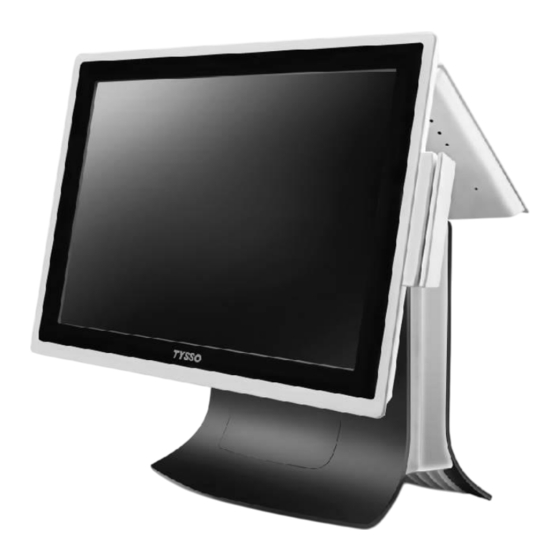
Parts Description Examining Your POS Terminal Parts Descriptions TOP I/O Cover D. 2 LCD Display A. Main LCD Display C. Modular Customer Display A1. MSR A2. -Button Side Cover (Right) B. Base Unit Side Cover (Left) Modular Main Board Figure 1 Parts of POS Unit... - Page 4 POS Unit Item Description Main LCD Display Modular LCD Display with Touch Screen. Metal Housing (with Top I/O Cover and Side Covers) Base Unit POS Modular Main Board Set and Main Power Adaptor Optional Peripherals Optional Peripherals Optional MSR Reader on the side of Main LCD Display Optional i-Button Module on the side of Main LCD i-Button Display...
-
Page 5: Main Board Layout
Main Board Layout ● Main Board Connection / Installation Notes The images below indicate the connectors and jumpers of the main board. Each connector/slot is used for the specified part or optional peripheral. Please refer to the notes as below and examine the layouts of the main boards to locate the connectors so as to complete the installation. - Page 6 ● Main Board Memory Slot 1 SATA DATA (Main Slot) (COMBO USB) Connectors SATA POWER JDIO1 JCMOS1 MINI CARD 1_1 JCASE1 LPT1 (Parallel Port) JLPC1 Jumper 1-6 Speaker (SP2) Speaker (SP1) MIC1 LOUT1 CASH 1 USB 1 USB 2 VGA_Power USB 3/4 VGA 1 COM 1...
- Page 7 Front View (Layout)
- Page 8 eDP* LVDS Rear View...
-
Page 9: Figure 2 Main Board
Rear View (Layout) Figure 2 Main Board Note: The eDP connector is for customized model Only and is not available for standard model. -
Page 10: System Disassembly
System Disassembly Before You Start To prevent injuries to the LCD Panel: Carefully Place the POS terminal on a flat, clean and stable surface (for example: a stable long table) Prepare additional cushioned material (for example: a soft, clean blanket). ... -
Page 11: B Disconnect The Devices On The I/O Ports
Disconnect the Devices on the I/O Ports There are some of the optional peripherals installed onto the POS system. Please detach the peripherals and store them in a secure location. Note: Please turn off the whole POS system and unplug the power cables from the electrical outlet. - Page 12 Disconnect the Power Cable from the POS unit. Bottom I/O Ports with connected cables Disconnect the Power Cable from the Power Adaptor Disconnect all of the connected cables on the Bottom I/O Ports. Bottom I/O Ports (Cables Disconnected) Note: Always store the Power Cable and the other disconnected cables/devices in a secure location for further use.
-
Page 13: Remove The Main Lcd Unit
Remove the Main LCD Unit Press the two sides and pull up to remove the TOP I/O Cover. Top I/O Cover There are LVDS cable and COMBO USB cable in the Base Unit of POS Terminal Base Unit. Unplug the LVDS cable. LVDS Cable (Left) and COMBO USB Cable (Center) Unplug the LVDS Cable... - Page 14 Disconnect the COMBO USB Connector from the TOP I/O Port. TOP I/O Ports and Main LCD Unit Securing Screws Use a screw driver to remove the (as RED marks indicated) four securing screws of the Main LCD Unit. Detach the Main LCD Unit from the Base Unit. Main LCD Unit with MSR Module.
-
Page 15: Remove The Msr Or I-Button Module From The Main Lcd Unit
Remove the MSR or i-Button Module from the Main LCD Unit Remove two Protective Caps of MSR Module with care. Main LCD Unit with MSR Module. Use a screw driver to loosen and remove the securing screws. Protective Caps of MSR Module Loosen the securing screws of MSR Module Disconnect the ribbon cable connector of MSR Module from the... - Page 16 Side I/O Port Protection: If the Side I/O Port of the Main LCD Unit is not in use, please install the protect cover onto the I/O Port. Side I/O Port of the Main LCD Unit and the Protective Cover (Left) Note: Always store the detached MSR Module (or i-Button) and screws in a secure location for further use.
-
Page 17: Remove The Secondary Lcd Display (Optional)
Remove the Secondary LCD Display (Optional) Press the two sides and pull up to remove the TOP I/O Cover. Top I/O Cover Secondary LCD Display Lift up the POS Unit and examine the Bottom I/O connectors. Disconnect the connectors of Secondary LCD Display. - Page 18 Arrange the cables and remove the Secondary LCD Display from the Base. Base Unit (Secondary LCD Display detached) Secondary LCD Display Note: Store the detached Secondary LCD Display and securing screws in a secure location for further use.
-
Page 19: Remove The Customer Display (Optional)
Remove the Customer Display (Optional) Press the two sides and pull up to remove the TOP I/O Cover. Top I/O Cover Lift up the POS Unit and examine Customer Display the Bottom I/O connectors. Disconnect the connectors of Customer Display. Disconnect the Connectors of Customer 12VDC Power Output (Left) and Display from the Bottom I/O Ports. - Page 20 Arrange the cables and remove the Secondary LCD Display from the Base Unit. Base Unit (Customer Display detached) Customer Display Note: Store the detached Customer Display and securing screws in a secure location for further use or maintenance.
-
Page 21: C Remove The Hdd/Ssd Drive From Pos Unit
Remove the HDD/SSD Drive from POS Unit Lay the POS unit face down on the surface*. Note: To prevent injuries to the LCD Panel, Carefully lay the front of the POS face down on a flat, clean and stable surface with additional cushioned material (for example: blanket). - Page 22 TIP: Replace the HDD/SSD Drive To replace the HDD/SDD Drive: Remove the securing screws of HDD/SSD Module (in the LEFT/RIGHT side). Replace a new HDD or SSD drive and re-install to the HDD Bracket. Power DATA Connector Connector Securing Screw Hole Use a Screw Driver to Replace a new HDD/SSD Drive and Remove all the securing screws...
-
Page 23: D Modular Main Board Set
Modular Main Board Set Remove the Modular Main Board Set from the POS Unit Loosen and remove the securing screws from the POS Unit (as RED marks illustrated). Modular Main Board Set installed on the Base of the POS Unit. Remove the Securing Screws of the Modular Main Board Set. - Page 24 Modular Main Board Unit Power Adaptor Note: Store the screws in a secure location for further use.
-
Page 25: Remove The Power Adaptor From The Modular Main Board Set
Remove the Power Adaptor from the Modular Main Board Set Loosen and remove the securing screws of the Metal Brackets. Then detach the Power Adaptor from the Main Board Set. Power Adaptor and Brackets on the back of the Main Board Set Remove the Securing Screws of the Metal Brackets The Securing Screws of Power Adaptor... -
Page 26: Remove The Hdd/Ssd Drive From The Modular Main Board Set
Remove the HDD/SSD Drive from the Modular Main Board Set Use a screw driver to remove the HDD/SSD Drive from the Modular Main Board Set. (Please refer to Remove the HDD/SSD Drive from POS Unit Modular Main Board Set Loosen the Securing Screw of HDD/SSD Drive Slot Remove the HDD Connector from the Metal HDD Slot. - Page 27 There are two securing screws on the Metal HDD Slot. Use a screw driver to remove the Metal HDD Slot from POS Unit: DATA Power Connector Connector HDD Connector on the HDD Slot Power Connector (Left) DATA Connector (Right) Loosen and Remove the Securing Screw of Metal HDD Slot (A) Metal HDD Slot Loosen and Remove the...
-
Page 28: Disconnect The Hdd Cable
Disconnect the HDD Cable Disconnect the HDD Cable (Power and Data Connectors) from the Main Board. Disconnect the connectors of HDD Cable The HDD Cable: from the Main Board Data Connector (RED) Power Connecter (Black) HDD cable Note: There is a cable binder on the HDD cable. Cut the cable binder before disconnect the HDD cable. -
Page 29: Disconnect The Parallel (Prt) Port (For Customized Model Only)
Disconnect the Parallel (PRT) Port (for Customized Model ONLY) Disconnect the connector of Parallel Port from the Main Board. Parallel Port (PRT) The Connector of Parallel Port on the Main Board Use a HEX screw driver to remove the securing screws of 25-pin Parallel Port connector. -
Page 30: Remove The Speaker (Audio) From Main Board
Remove the Speaker (Audio) from Main Board Disconnect the Red-Black twisted cable of Speaker from the Main Board. Disconnect the Speaker from Main Board The Speaker Disconnect the Red-Black twisted cable from the Main Board Loosen the securing screws and remove the Speaker. -
Page 31: Disconnect The Db9 Com Port (Com 4)
Disconnect the DB9 COM Port (COM 4) Disconnect the connector of COM Port from the Main Board. The Connector of COM Port COM Port (COM 4) (COM 4) on the Main Board Use a HEX screw driver to remove the securing screws of COM Port connector. -
Page 32: Remove The Ram Module
Remove the RAM Module Release the latches on the two sides of the RAM module slot. Ram Module on the Main Board (SODIMM_A1) Gently slide the module out of the slot The RAM Module To Replace or Re-Install the RAM Module: Install the RAM Module to the RAM Module slot. -
Page 33: Disassemble The Main Board Set
Disassemble the Main Board Set Bottom I/O Ports: Use a HEX screw driver to remove the securing screws of COM Port connectors and VGA Port. Main Board Set Main Board Securing Screws: Remove the securing screws of the Main Board. Bottom I/O Ports: The DB9 COM Ports (COM 1/2/3) and VGA Port... - Page 34 TOP I/O Port: Use a HEX screw driver to remove the securing screws of COMO USB Port. TOP I/O Port (COMBO USB) Remove the securing screws of Metal Bracket of TOP I/O Port. Detached Metal Bracket of TOP I/O Port Securing Screw of TOP I/O Bracket and Modular Main Board Set Slide and remove the Main Board from the...
-
Page 35: Cmos Battery Replacement
CMOS Battery Replacement If you notice that the system date and time often reset to the factory date (older date and time) and need to adjust when the POS terminal is powered off and on, the battery is probably starting to fail and should be replaced. CAUTION ALL BATTERY SERVICING OR REPLACEMENT MUST BE PERFORMED BY A QUALIFIED SERVICE TECHNICIAN. -
Page 36: E Base Unit Maintenance
Base Unit Maintenance The Base Unit may needs maintenance during a certain operation time. For parts replacement, please purchase the service parts from manufacturer or authorized distributer ONLY. Base Unit (Bottom View) The Base Unit with two Side Covers Press the edge and pull-up to remove the Side Covers Install the new Side Covers to the Base Unit Press the edge and pull-up the Side Cover... - Page 37 Revision History Date Version Note Description Mar. 05, 2018 Ver. 1.0 Preliminary version TP-8515 Disassemble Instruction.
Need help?
Do you have a question about the TP-8515 and is the answer not in the manual?
Questions and answers