Table of Contents
Advertisement
Quick Links
Download this manual
See also:
User Manual
Advertisement
Table of Contents

Related Manuals for Fametech TP-2515


Summary of Contents for Fametech TP-2515
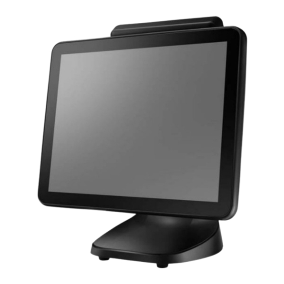
- Page 1 Service Manual TP-2515 Fanless Full Flat Touch Screen POS System Service Manual Version 1.0 © Copyright Fametech Inc. (TYSSO) 2019...
-
Page 2: Table Of Contents
Table of Contents System Disassembly ................. 1 Before You Start ..................1 Remove all the Peripherals (MSR, i-Button Module, or Customer Display) from the POS Unit ..................2 Disconnect the Devices from the I/O Ports ..........3 Unplug the cables from the POS Unit.............. 3 Remove the HDD/SSD Drive from POS Unit .......... -
Page 3: System Disassembly
System Disassembly Before You Start To prevent injuries to the LCD Panel: Carefully Place the POS terminal on a flat, clean and stable surface (for example: a stable long table) Prepare additional cushioned material (for example: a soft, clean blanket). ... -
Page 4: B Remove All The Peripherals (Msr, I-Button Module, Or Customer Display) From The Pos Unit
Remove all the Peripherals (MSR, i-Button Module, or Customer Display) from the POS Unit Please refer to the User Manual for the instructions of installation and disconnection procedures. POS Unit with MSR and i-Button POS Unit with Customer Display POS Unit without Optional Peripherals Note: Always store the detached MSR Module (or i-Button) and screws in a secure location for further use. -
Page 5: C Disconnect The Devices From The I/O Ports
Disconnect the Devices from the I/O Ports There are some of the optional peripherals or devices installed onto the POS system. Please detach the peripherals/devices and store them in a secure location. Note: Please turn off the whole POS system and devices before unplugging the cables from the I/O ports. -
Page 6: D Remove The Hdd/Ssd Drive From Pos Unit
Remove the HDD/SSD Drive from POS Unit Remove the Protective Cover. Remove the Securing Screws of HDD/SSD Drive Slot with Protective Cover the HDD Drive Slot (Left) HDD Drive Module Loosen the Securing Screw of the HDD Drive Slot Pull out the HDD Drive Module Pull out the HDD Drive Module... - Page 7 TIP: Replace the HDD/SSD Drive To replace the HDD/SDD Drive: Remove the securing screws of HDD/SSD Module. Replace a new HDD or SSD drive and re-install to the HDD Bracket. HDD Bracket (Left), SSD Drive (Right) and Securing Screws (Up) When Disassembling: Please disassemble the HDD/SSD drive and HDD Bracket correctly.
-
Page 8: E Detach The Panel Unit (With Main Board) From The Base Unit
Detach the Panel Unit (with Main Board) from the Base Unit Push upward and release the two Slide Locks (Left and Right) on the back of the POS unit. Slide Lock (Left) Slide Lock (released) Slide Lock on the back of POS Unit Lift the Panel Unit from the Back Cover. -
Page 9: F Panel Unit (With Main Board Set)
Panel Unit (with Main Board Set) Remove the HDD/SSD Drive from the Modular Main Board Set Use a screw driver to remove the HDD/SSD Drive from the Modular Main Board Set. (Please refer to D. Remove the HDD/SSD Drive from POS Unit.) Remove the HDD Connector from the Metal HDD Slot (Red Marks). -
Page 10: Disconnect The Hdd Cable
Disconnect the HDD Cable Disconnect the HDD Cable (Power and Data Connectors) from the Main Board. Disconnect the connectors of HDD Cable The HDD Cable: from the Main Board Data Cable (RED) and Power Cable (Black) HDD cable Note: If there is a cable binder on the HDD cable, cut the cable binder and disconnect the HDD cable from the main board. -
Page 11: Disconnect The Touch Controller From The Main Board
Disconnect the Touch Controller from the Main Board Disconnect the connector of Parallel Port from the Main Board. The Touch Controller on the Panel Unit Panel Unit Use a HEX screw driver to remove the securing screws of 25-pin Parallel Port connector. Disconnect the connector of the Touch Cable from the Main Board. -
Page 12: Vga/12Vdc Output Cable
VGA/12VDC Output Cable There is a VGA/12VDC Out cable on the main board. You can arrange the cable to remove the other cables or connectors from the main board. To remove the cable, disconnect the connectors and remove the cable from the main board. -
Page 13: Disconnect The Side I/O Cable From The Main Board
Disconnect the Side I/O Cable from the Main Board Disconnect the connectors Remove the Connectors from the clip from the Main Board Side I/O Cable... -
Page 14: Disconnect The Side I/O Cable And Speaker From The Main Board
Disconnect the Side I/O Cable and Speaker from the Main Board Release the Side I/O Connector from the clip on the Panel Unit and then remove the Side I/O Cable from the main board. Side I/O Connector Clip Speaker... -
Page 15: Disconnect The Power Switch And Led Indicator From The Main Board
Disconnect the Power Switch and LED Indicator from the Main Board LED Indicator Power Switch... -
Page 16: Disconnect The Lvds And Invertor Connectors From The Main Board
Disconnect the LVDS and Invertor Connectors from the Main Board Invertor LVDS... -
Page 17: Remove Main Board From The Panel Unit
Remove Main Board from the Panel Unit Use a HEX screw driver to remove the hex spacers of COM Port connectors and VGA Port. Hex Spacers of Bottom I/O Ports Bottom I/O Ports (Hex Spacers removed) - Page 18 Push forward and pull up to remove the Main Board from the Panel Unit. Push Forward to Remove the Main Board from the Panel Unit Disconnect the Side I/O Cable and COM Port Cable from the main board.
-
Page 19: Remove The Ram Module
Remove the RAM Module Release the latches on the two sides of the RAM module slot. Ram Module on the Main Board Pull and remove the module out of the slot with care. The RAM Module To Replace or Re-Install the RAM Module: Install the RAM Module to the RAM Module slot. -
Page 20: Remove The Metal Bracket Of Bottom I/O Port
Remove the Metal Bracket of Bottom I/O Port Use a screw driver to remove the securing screws of the metal bracket from the Panel Unit. Securing Screws of the Metal Bracket... -
Page 21: Remove The Speaker And Power Switch From The Panel Unit
Remove the Speaker and Power Switch from the Panel Unit Remove the tapes on the Panel Unit and remove the Speaker and Power Switch from the Panel Unit. Speaker Power Switch LED Indicator Tips: Use a needle nose pier to press the two sides of the power switch; and push to remove from the metal bracket. -
Page 22: Remove The Securing Screws Of The Touch Controller
m. Remove the Securing Screws of the Touch Controller Panel Unit with Touch Controller Remove the Securing Screws of the Touch Controller Touch Controller (with Securing Screws) Warning DO NOT Disassemmble the Touch Controller from the Front Bezel Set. - Page 23 The Touch Controller is detached from the Metal Panel Bracket Warning DO NOT Disassemmble the Touch Controller from the Front Bezel. The Touch Controller is a part of the Front Bezel Set and nee not separate apart.
-
Page 24: Detach The Lcd Panel From The Front Bezel Set
Detach the LCD Panel from the Front Bezel Set Securing Screws of Metal Panel Bracket Remove the securing screws to detach the Metal Panel Bracket from the Front Bezel Set. RED: Securing Screws with Metal Plate (1 Plate with 2 Screws). Remove the Securing Screws Remove the Metal Plate Metal plate (Short) -
Page 25: Led Indicator
Front Bezel Set Panel Bracket with LCD Panel LED Indicator Remove the LED Indicator from the Front Bezel Set... -
Page 26: Detach The Lcd Panel Front The Metal Bracket
Detach the LCD Panel front the Metal Bracket LCD Panel (Left) and Metal Bracket (Right) Securing Screws of the Metal Bracket (Left and Right side) -
Page 27: G Replace The Power Adaptor
Replace the Power Adaptor The Base Unit may needs maintenance during a certain operation time. For parts replacement, please purchase the service parts from manufacturer or authorized distributer ONLY. Pull and Remove the Top Cover The Rear View of POS Unit of the Base Unit Pull backward to remove the Rear Cover. - Page 28 Remove the Securing Securing Screws of the Metal Bracket Screws of the Metal Bracket. for Power Adaptor Power Adaptor and Metal Bracket...
- Page 29 Revision History Date Version Note Description Jan. 31, 19 Ver. 1.0 beta Preliminary version TP-2515 Disassemble Instruction.
Need help?
Do you have a question about the TP-2515 and is the answer not in the manual?
Questions and answers