PerkinElmer FL 6500 Installation Instructions Manual
Single cell peltier holder
Hide thumbs
Also See for FL 6500:
- Installation instructions manual (6 pages) ,
- Installation instructions manual (18 pages) ,
- Installation instructions manual (10 pages)
Advertisement
This instruction sheet describes the installation of this accessory which is used with the FL 6500/8500
Fluorescence Spectrometer.
Read these instructions before you install this accessory.
NOTE:
Contacting P erkinElm er
Supplies, replacement parts, and accessories can be ordered directly from PerkinElmer, using the part
numbers.
See our website:
http://perkinelmer.com
PerkinElmer's catalog service offers a full selection of high-quality supplies.
To place an order for supplies and many replacement parts, request a free catalog, or ask for information:
If you are located within the U.S., call toll free 1-800-762-4000, 8 a.m. to 8 p.m. EST. Your order will be
shipped promptly, usually within 24 hours.
If you are located outside of the U.S., call your local PerkinElmer sales or service office.
Features
•
Full software control
•
Liquid cooling system
•
N
gas purging available
2
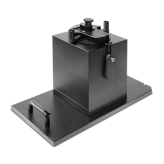
Figure 1 Single Cell Peltier Holder [P/N: N4201029]
FL 6500/ 8500 Single Cell Peltier Holder
I nstallation I nstructions
PerkinElmer, 710 Bridgeport Avenue,
Shelton, CT 06484-4794, U.S.A
Produced in the USA.
09931519A
Advertisement
Table of Contents

Subscribe to Our Youtube Channel
Related Manuals for PerkinElmer FL 6500


Summary of Contents for PerkinElmer FL 6500
- Page 1 09931519A FL 6500/ 8500 Single Cell Peltier Holder I nstallation I nstructions This instruction sheet describes the installation of this accessory which is used with the FL 6500/8500 Fluorescence Spectrometer. Read these instructions before you install this accessory. NOTE: Contacting P erkinElm er Supplies, replacement parts, and accessories can be ordered directly from PerkinElmer, using the part numbers.
-
Page 2: Dimensions And Specifications
09931519A Dim ensions and Specifications Peltier Tem perature Controller 201 Physical Characteristic Specification Power 100-240 VAC, 50/60 Hz, 380W Temperature Range -5 to 100°C (Maximum Internal Temperature) Maximum Ambient Operating Temperature 40°C 295 (W) x 416 (D) x 283 (H) mm Dimensions (11.6 (W) x 16.4 (D) x 11.1 (H) in) Weight... -
Page 3: Safety Warnings
09931519A Safety W arnings When this label is attached to an instrument it means refer to the manual. WARNING Lorsque cette étiquette est attachée à un instrument, il est nécessaire de voir le manuel. AVERTISSEMENT There is risk of receiving a fatal electric shock if the fuses are replaced with the power cord connected. - Page 4 09931519A Configuration of Single Cell P eltier Holder Part Name Qty (ea) Single Cell Peltier Holder Peltier Temperature Controller 201 Power Cords 3 (US, UK, EU) Interface Cable (USB) Spare Fuse (AC 250V T5AL) Temperature Probe Stirring Bead Coolant Hose Coolant (700 mL) Waste Basket for Coolant Waste Hose for Coolant...
- Page 5 09931519A f. Temperature Probe P eltier Tem perature Controller 201 Front View of Peltier Tem perature Controller 201 Figure 3 Front view a. Flow Gauge: Indicator of the flow rate of N2 gas b. Coolant Inlet c. LED Indicators: Display the status of the operation of coolant circulation, fan, pump, etc. (If there is any problem in the components, the red LED will flash with the beep alarm.) d.
- Page 6 09931519A R ear View of Peltier Tem perature Controller 201 Figure 4 Rear view a. Air Vent Manual button: It is used to identify the cause of warning alarm that sounds when the trouble occurs with Peltier. The causes of the alarm are as follows; i.
- Page 7 09931519A How to Fill or Drain the Coolant How to Fill the coolant NOTE: When the Single Cell Peltier Holder is installed for the first time, the enclosed coolant should be filled by following this procedure. Prepare the Peltier Temperature Controller 201 in a location that is compatible with the required environmental conditions for the operation.
- Page 8 09931519A Push the Air Vent Manual Button on. Figure 8 Push the button Turn on the AC power switch of the Peltier Temperature Controller 201. Figure 9 Turn on the AC power switch Check if the LEDs of LOW LEVEL and FLOW SENSOR are lit on. Figure 10 LEDs of LOW LEVEL and FLOW SENSOR Open the lid of the coolant inlet on top of the Peltier Temperature Controller 201 and fill up the liquid coolant using a funnel.
- Page 9 09931519A Maintain the amount of liquid coolant to a level where the indicator is located between the ‘L’ (low) and ‘H’ (high) mark in the scale on the left side of the Peltier Temperature Controller. Figure 12 Coolant level Liquid coolant should be used as refrigerant. Do not use any water (tab CAUTION water, DI, etc.).
- Page 10 09931519A Turn off the AC power switch of the Peltier Temperature Controller 201. Push the Air Vent Manual button off. Fasten the four Phillips screws on the Air Vent Manual button cover using a screwdriver. Install the Single Cell Peltier Holder referring to section Installation (see page 12). How to Drain the Coolant Turn off the Peltier Temperature Controller 201.
- Page 11 09931519A Turn on the AC power switch of the Peltier Temperature Controller 201. Figure 17 Turn on the AC power switch Connect the waste hose to the Coolant Drain port on the rear panel. Figure 18 Connect the waste hose The coolant flows out as soon as the waste hose is connected, so the other side of the waste hose should be NOTE: placed into the waste basket before connected.
-
Page 12: Installation
Assurez-vous que l’instrument est éteint lors de l’installation de cet accessoire. ATTENTION Prepare the FL 6500/8500 and Peltier Temperature Controller 201 in a location that is compatible with the required environmental conditions for the operation. Connect the power cord and communication cable of the instrument. - Page 13 09931519A After checking the pogo pin position in the sample compartment, place the Single Cell Peltier Holder to be fit into the pogo pin. Figure 23 Inserting the Single Cell Peltier Holder Fix the front cover plate of the Single Cell Peltier Holder with the bolts. Figure 24 Fixing the Front Cover Plate Tighten the accessory fixing bolt again.
-
Page 14: Gas Fitting
09931519A Disconnect the hose for coolant circulation. Figure 26 Disconnecting the hose for the coolant circulation NOTE: If you disconnect the hose, the remaining coolant in the hose may flow out of the hose. Be careful not to touch the coolant with your bare hands. Connect the coolant inlet/outlet hosed and N gas tube between the Peltier Temperature Controller 201 and the Single Cell Peltier Holder. - Page 15 Connect the power cord to the Peltier Temperature Controller 201. Figure 30 Connecting the power cord Turn on the power switch of the FL 6500/8500 and the Peltier Temperature Controller 201. The air vent manual button should be off before turning on the main power of the...
- Page 16 Setting USB Serial P ort NOTE: When using the USB cable, USB Driver has already been installed when installing the FL 6500/8500 and Spectrum FL software, you do not need to install it again. If communication by the USB is not established, change the port setting as follows;...
- Page 17 09931519A Select Device Manager. Select Ports (COM & LPT) to scroll down. These are the devices currently connected to the COM ports. USB Serial Port (COMx) is listed when the driver installation is completed successfully. Double click on the USB Serial Port (COMx) of the Ports (COM & LPT). Select the Port Settings tab and select the Advanced…...
- Page 18 09931519A Set the parameters as shown below. Select OK. If the Peltier Temperature Controller 201 fails to communicate with the PC, change the COM Port Number by the following steps. Open the Advanced Setting for COMx window again by repeating the steps 1 to 6. Select the COM Port number list to scroll down it and change the COM port number to another one which is not in use, for example COM 1 to COM 10.
- Page 19 09931519A 11. Make sure that the changed COM Port Number is applied and select OK. 12. After the port setting is changed, restart the computer. M easurem ent Install the Single Cell Peltier Holder by referring to section Installation (see page 12). Close the sample compartment cover and turn on the instrument.
-
Page 20: Temperature Display
09931519A Set the parameters of for the probe, temperature and temperature display settings. This function is used to adjust temperature. It is only used for the Probe Settings manufacturing process, so do not modify the values. Temperature settings Select the temperature used to monitor during measurement. Options Monitor include: Block, Probe 1 or Probe2. - Page 21 09931519A Set parameters for the experiment in the Data Collection tab. NOTE: For more detail of method, refer to Spectrum FL Software Users Guide. In the Accessory tab, select Single Cell Peltier Holder. Select Constant or Ramp mode in the Single Cell Peltier Holder Temperature Mode. The measurement is only performed with isothermal state in the Constant mode constant mode.
- Page 22 09931519A Ramp mode The Ramp mode can be set up according to desired temperature conditions. Start (℃) Enter the start temperature for the measurement. End (℃) Enter the end temperature for the measurement. Enter the measurement interval temperature. For instance, you set 5℃, the Interval (℃) sample will be measured from start temperature to end temperature every 5℃.
- Page 23 1. Connect the accessory interface cable of the Peltier Temperature Controller 201 to the connector of the peltier cell changer. 2. Turn on the power switch of the FL 6500/8500 and the Peltier Temperature Controller 201. 3. Double-click on the Spectrum FL software and select a measurement mode.
-
Page 24: Troubleshooting
09931519A 5. Click Connect 6. Click Auto Tuning. Auto Tuning will start. 7. Click OK when the Auto tuning succeeded. message pops up. Troubleshooting POW ER LED is not lit on Check the connection of the power cord or the fuse. The fuse is located at the rear of the instrument. - Page 25 09931519A Carefully open the compartment latch where the fuse is located. Location of the latch on the fuse compartment door Disconnect the fuse. Replace with a new T5ALfuse (AC 250V). One spare is contained in the power module. Close the compartment door. Plug in the instrument and turn on.
- Page 26 09931519A Remove the four Phillips screws on the Air Vent Manual button cover using a screwdriver. Push the Air Vent Manual button on. Restart the Peltier Temperature Controller 201 and check the coolant level and if it is below the ‘L’ (low) mark, fill up the coolant adequately.
- Page 27 09931519A FLOW SENSOR and PUM P LED is lit on w ith an alarm sound Turn off the power of the Peltier Temperature Controller 201. Remove the four Phillips screws on the Air Vent Manual button cover using a screwdriver. Push on the Air Vent Manual button.
- Page 28 Push off the Air Vent Manual button. Fasten the four Phillips screws on the Air Vent Manual button cover using a screwdriver. If the FLOW SENSOR and PUMP LED is continuously on, contact your PerkinElmer Service representative. Connection is failed...
Need help?
Do you have a question about the FL 6500 and is the answer not in the manual?
Questions and answers