Table of Contents
Advertisement
Quick Links
Advertisement
Table of Contents

Related Manuals for PerkinElmer Spotlight 400 Series


Summary of Contents for PerkinElmer Spotlight 400 Series
- Page 1 MOLECULAR SPECTROSCOPY Spotlight 400 Series User’s Guide...
- Page 2 The information contained in this document is subject to change without notice. Except as specifically set forth in its terms and conditions of sale, PerkinElmer makes no warranty of any kind with regard to this document, including, but not limited to, the implied warranties of merchantability and fitness for a particular purpose.
-
Page 3: Table Of Contents
Contents Introduction ....................7 About This Manual .................... 8 Conventions Used in this Manual ................ 9 Notes, Cautions and Warnings ..............9 Definitions ....................12 Related Documents ..................12 Requirements for using the Imaging System ..........12 Connecting the PC to the Local Area Network ..........12 Warnings and Safety Information ............ - Page 4 Specialized Accessories ................51 Items to Have Available ................52 Common Window Materials ................53 Techniques for Preparing Samples ..............54 Flattening Solids ..................54 Slicing Samples from Solids ............... 55 Polymers ....................56 Particles ....................59 Fibers ....................... 60 Fibrous Solids ...................
- Page 5 Installing the SpectrumIMAGE software ............ 109 Appendix 2: Amending the Power Options Display Settings ....... 114 Power Options ..................114 Display Options ..................114 Appendix 3: Decontamination ................. 116 Appendix 4: WEEE Instructions for PerkinElmer Products ........117 Index ......................118...
-
Page 7: Introduction
Introduction... -
Page 8: About This Manual
8 . Spotlight 400 Series User’s Guide About This Manual This introduction gives you information about this manual, to enable you to use it effectively when learning to operate the imaging system. Before you start using your Spotlight imaging system we recommend that you: •... -
Page 9: Conventions Used In This Manual
ALT+F. All eight digit numbers are PerkinElmer part numbers unless stated otherwise. ‘Spectrometer’ refers to the Frontier IR System, Spectrum 100 Series, Spectrum 400 Series, Spectrum One FT-IR or Spectrum One NTS FT-NIR spectrometer used with your Spotlight imaging system. - Page 10 10 . Spotlight 400 Series User’s Guide We use the term CAUTION to inform you about situations that could CAUTION result in serious damage to the instrument or other equipment. Details about these circumstances are in a box like this one.
- Page 11 Introduction . 11 We use the term WARNING to inform you about situations that could result in personal injury to yourself or other persons. Details about these circumstances are in a box like this one. WARNING Warning (Warnung) Bedeutet, daß es bei Nichtbeachten der genannten Anweisung zu einer Verletzung des Benutzers kommen kann.
-
Page 12: Definitions
12 . Spotlight 400 Series User’s Guide Definitions OPERATOR: Person operating the equipment for its intended purpose. RESPONSIBLE BODY: Individual or group responsible for the use and maintenance of the equipment and for ensuring that the OPERATORS are adequately trained. -
Page 13: Warnings And Safety Information
Warnings and Safety Information... -
Page 14: The Spotlight Imaging Systems
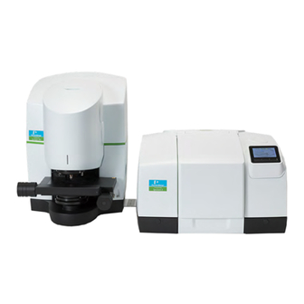
14 . Spotlight 400 Series User’s Guide The Spotlight Imaging Systems The dual-range Spotlight 400 imaging system consists of an FT-IR imager, filter box, dual-range spectrometer (Frontier FT-IR/FT-NIR or Spectrum 400 FT-IR/FT-NIR), PC, stage controller and joystick. NOTE: The Spotlight 400 imaging system with a Frontier FT-IR/FT-FIR or Spectrum 400 FT-IR/FT-FIR spectrometer operates in the MIR range only. -
Page 15: Summary
Warnings and Safety Information . 15 Summary The PerkinElmer Spotlight 400 series imaging systems have been designed to comply with a wide variety of international standards governing the safety of laboratory equipment. In routine use, the imaging system poses virtually no risk to you. If you take some simple, common sense precautions, you can make sure that you maintain the continued safe operation of the imaging system. -
Page 16: General Operating Conditions
16 . Spotlight 400 Series User’s Guide General Operating Conditions For information about the Spectrometer, refer to the User’s Guide supplied with the IR & Raman Manuals CD instrument. The (L1050002) includes instrument manuals for the Frontier IR Systems, Spectrum 400 Series and Spectrum 100 Series spectrometers. -
Page 17: Electrical Safety
Electrical Safety The imager and stage controller have been designed and tested in accordance with PerkinElmer specifications and in accordance with the safety requirements of the International Electrotechnical Commission (IEC). The imager and stage controller conform to IEC 61010-1 (Safety Requirements for electrical equipment for measurement, control, and laboratory use) as it applies to IEC Class 1 (earthed) appliances and therefore meet the requirements of EC low voltage directive 2006/95/EC. -
Page 18: Location And Ventilation
Location and Ventilation To allow for adequate cooling The imaging system is installed by a PerkinElmer Service Engineer, who will be able to advise on the siting of the system. To allow for adequate cooling, the system should not be sited near to room heating equipment, for example, central heating radiators. -
Page 19: Warning Labels On The Instrument
Warnings and Safety Information . 19 Warning Labels on the Instrument Caution, risk of electric shock. Caution, Risk of Danger When this label is attached to an instrument it means ‘Caution, risk of danger’. Refer to the manual to find out the nature of the potential hazard and any actions that have to be taken. - Page 20 20 . Spotlight 400 Series User’s Guide Power 100-230V ~50/60Hz 75 VA Figure 3 Labels (rear of imager) Figure 4 Label (inside dewar lid) Cooling the MCT Detector Refer to on page 41. Warning Disconnect supply cord before opening MAINS INPUT 100 –...
-
Page 21: Mechanical Safety
Warnings and Safety Information . 21 Mechanical Safety When you are using a motorized stage, do not place your fingers between the moving and fixed parts of the stage. The motors driving the stage from side to side, front to back, or up and down are powerful and do not stall easily. -
Page 22: Lifting The Spotlight Imaging System
22 . Spotlight 400 Series User’s Guide Lifting the Spotlight Imaging System The imager and spectrometer are heavy precision instruments, so two people are required for safe handling. Consult the local codes of practice issued by safety advisors before WARNING attempting to lift these instruments. -
Page 23: Emc Compliance
Warnings and Safety Information . 23 EMC Compliance EC Directive The Spotlight 400 series imaging systems have been designed and tested to meet the requirements of EMC Directive 2004/108/EC. FCC Rules and Regulations This product is classified as a digital device used exclusively as industrial, commercial, or medical test equipment. -
Page 24: System Requirements
24 . Spotlight 400 Series User’s Guide System Requirements Give attention to the following points before installing the imaging system. Electrical Requirements The power consumption of the imager does not exceed 75 VA. The power consumption of the stage controller does not exceed 60 VA. The nominal power consumption of the spectrometer is 120 VA. -
Page 25: Safety Specifications
Warnings and Safety Information . 25 Safety Specifications Imager Power supply 100–230 V ±10%, 50/60 Hz, ±10% Primary fuse 2.0 A, time-lag Weight 32 kg without the motorized stage Stage Controller Power supply 100–240 V ±10%, 50/60 Hz Primary fuse 1.6 A T, (time-lag) The stage controller is not designed for use with all three motors simultaneously over extended periods. - Page 26 26 . Spotlight 400 Series User’s Guide...
-
Page 27: Overview Of The Spotlight Imaging System
Overview of the Spotlight Imaging System... -
Page 28: A Guided Tour Of The Spotlight Imaging System
28 . Spotlight 400 Series User’s Guide A Guided Tour of the Spotlight Imaging System The Spotlight 400 series imaging systems enable you to collect images from extremely small samples. The PerkinElmer cassegrain collection optics give high-performance infrared microspectroscopy. The imager includes a camera and viewing system that magnifies the visible-light image of the sample so that you can see, position, and isolate a point of interest. -
Page 29: Connections
Overview of the Spotlight Imaging System . 29 Connections Figures 6–9 show the input and output connections on the imager and stage controller. Connections to stage controller Figure 6 Connections to Stage Controller SP1 - connects to spectrometer external left port for single element detector output: 9-way D type, male AUX - connects to... - Page 30 30 . Spotlight 400 Series User’s Guide Stage Z - connects to stage controller for Z-motor drive Connects to PC: control RS232, 9-way D type Connects to stage controller: 15-way D type Figure 8 Electrical connections (bottom rear of imager)
-
Page 31: Modes Of Operation
Overview of the Spotlight Imaging System . 31 Modes of Operation The imager has three main modes of operation, namely Image mode, Point mode, and ATR Imaging mode. In Image mode you can quickly produce an IR image from a particular area of the sample. Simply indicate the area you want to scan by drawing a box around it, and then click a button to collect the IR image. -
Page 32: The Optical System
32 . Spotlight 400 Series User’s Guide The Optical System The imager has optics for infrared microspectroscopy and visible light. A video camera enables you to view the sample. The two systems intersect at the aperture. When a sample on the sample stage is in focus, its conjugate image is focused at the remote aperture. -
Page 33: Viewing In Transmittance
Overview of the Spotlight Imaging System . 33 Viewing in Transmittance When the imager is in viewing mode in transmittance (Figure 10): • The lower fold mirror, beneath the cassegrains, receives light from the LED source and directs it up through the lower dichroic mirror onto the lower cassegrain. •... -
Page 34: Viewing In Reflectance/Diffuse Reflectance
34 . Spotlight 400 Series User’s Guide Viewing in Reflectance/Diffuse Reflectance When the imager is in viewing mode in reflectance or diffuse reflectance (Figure 11): • The reflectance illuminator assembly directs light from the upper LED down through one side of the cassegrain onto the sample. -
Page 35: Collecting An Image
Overview of the Spotlight Imaging System . 35 Collecting an Image The upper cassegrain is used for both visible light and infrared radiation. For this reason, when you adjust the sample position so that the visible image of the sample is in focus, the sample is also correctly positioned for collecting the infrared image. -
Page 36: Collecting An Image In Reflectance/Diffuse Reflectance
36 . Spotlight 400 Series User’s Guide Collecting an Image in Reflectance/Diffuse Reflectance Collecting an image in reflectance or diffuse reflectance differs from viewing as follows (Figure 13): The toroid moves to send the beam to the Reflectance illuminator assembly dichroic •... -
Page 37: Spotlight Requirements
A Spotlight 400 series imaging system requires driver software and may require an additional card to be installed in the PC. If you encounter a problem with the PC, contact a PerkinElmer Service Engineer. Do not attempt to remove the card from the PC or install the software on another PC. -
Page 38: Software Requirements
38 . Spotlight 400 Series User’s Guide Software Requirements All Spotlight 400 imaging systems are supported by SpectrumIMAGE version 1.6 or later, which requires that a 32-bit operating system is installed on the PC, either Windows® XP Professional Service Pack 3, or later, or Windows® 7 Professional Service Pack 1, or later. -
Page 39: Getting Ready To Use The Imaging System
Getting Ready to use the Imaging System... -
Page 40: Before Using The Imaging System
40 . Spotlight 400 Series User’s Guide Before Using the Imaging System Before you use the Spotlight 400 series imaging system you must: • Make sure the spectrometer is switched on; • Switch the stage controller and imager on; •... -
Page 41: Cooling The Mct Detector
Getting Ready to use the Imaging System . 41 Cooling the MCT Detector When an MCT (Mercury Cadmium Telluride) detector is fitted in the imager, it must be cooled to 77 K before you collect spectra. It is mounted in a dewar that can be filled with liquid nitrogen. - Page 42 42 . Spotlight 400 Series User’s Guide Open the flap covering the dewar. 1. Remove the dewar cap. 2. Place the small funnel supplied with the imager in the opening in the detector dewar (Figure 14). Figure 14 The dewar opening with the funnel inserted Stand where you can see the inside of the funnel as you pour the nitrogen in.
-
Page 43: Setting Up The Imaging System
Collecting the Image of a Thick Sample BEFORE you select ATR Imaging mode. To set up your Spotlight 400 series imaging system for use in Image mode or Point mode: 1. Make sure the spectrometer is switched on. It can take the spectrometer up to two hours to equilibrate after being switched off overnight. -
Page 44: Focusing The Visible Image
44 . Spotlight 400 Series User’s Guide Focusing the Visible Image 1. Click in the Stage Control window to move the sample stage to the Load position. 2. Place your sample on the sample stage. 3. If you want to examine the sample in reflectance mode, click Reflectance on the Control dialog. -
Page 45: Fitting An Attenuator To The Spectrometer
Getting Ready to use the Imaging System . 45 Fitting an Attenuator to the Spectrometer If your Spotlight 400 system is supplied with an InGaAs detector, you will be provided with an Attenuator kit (part number L1160560) containing 1%T, 4%T, 6%T, 14%T and 32%T attenuators. - Page 46 46 . Spotlight 400 Series User’s Guide...
-
Page 47: Preparing Samples
Preparing Samples... -
Page 48: Sample Preparation
48 . Spotlight 400 Series User’s Guide Sample Preparation The Spotlight imaging system enables you to examine the sample in the Monitor Visible window and to select the area where you want to collect images or spectra. To make sure that you collect good quality spectra, it is important that you prepare samples properly. -
Page 49: Tools For Sample Preparation
Preparing Samples . 49 Tools for Sample Preparation This section lists the tools you need for preparing samples: • Tools provided with the imaging system; • Tools in the microsampling toolkit; • Materials to have available; • Specialized accessories you may want to purchase. Tools Provided with the Imaging System The following items for use in sampling are provided in the Sampling Accessories Kit that is supplied:... - Page 50 50 . Spotlight 400 Series User’s Guide Figure 16 Some of the tools in the microsampling toolkit The following tools are provided in the Microsampling toolkit: Tool Steel tweezers Picking up extremely small objects Roller knife Cutting (knife end) and flattening (roller end)
-
Page 51: Other Useful Tools
1.5 mm microdisk. Fits in 13 mm disk holder to support very 01861043 small samples. These items are available from your local PerkinElmer sales office or agent. Specialized Accessories The following accessories are extremely useful in preparing certain types of samples (as... -
Page 52: Items To Have Available
52 . Spotlight 400 Series User’s Guide Items to Have Available In addition to the items provided with the Spotlight imaging system, we recommend that you have the following available: • Tape with adhesive on both sides (“double-sided tape”) for holding long or large samples on the sample stage;... -
Page 53: Common Window Materials
Preparing Samples . 53 Common Window Materials For work in the mid-infrared using the Spotlight 400 imaging system, both liquid and solid samples are often mounted on salt windows. Very thin windows, 1 to 2 mm thick, give the best spectra. The following materials are commonly used in windows: KBr: Potassium bromide is inexpensive, and it transmits infrared radiation to below •... -
Page 54: Techniques For Preparing Samples
54 . Spotlight 400 Series User’s Guide Techniques for Preparing Samples This section describes some useful techniques for preparing various types of samples. Flattening Solids Flattening samples by pressing or squeezing often enables you to make thick samples thin enough to give good infrared spectra. Because the samples are usually quite small, only moderate force is necessary. -
Page 55: Slicing Samples From Solids
Preparing Samples . 55 Pressing with the heel of a probe Press on small samples with the flat end of the probe handle. Even moderate pressure usually produces considerable thinning. Pressing with a needle Pressing with the point of a needle or probe applies a high force per unit area, because the area of contact is small. -
Page 56: Polymers
56 . Spotlight 400 Series User’s Guide Microtoming A microtome enables you to slice a sample into thin cross-sections, 0.5 to 20 µm thick. It is commonly used to prepare samples for light microscopy; the same range of thicknesses is also appropriate for infrared microspectroscopy. - Page 57 Preparing Samples . 57 4. Put the top half back on the cell, lining up the red dots on the top and bottom halves. Do not tighten the screws yet; applying uneven shear forces may damage the diamonds. One diamond can damage another. CAUTION 5.
- Page 58 58 . Spotlight 400 Series User’s Guide Filled polymers When a polymer contains a high concentration of fillers, and you want to analyze the polymer, you have to prepare a sample for analysis that is free of filler. Often you can obtain a suitable sample by cutting a thin wedge of the material with a sharp blade.
-
Page 59: Particles
Preparing Samples . 59 Particles Crushing Crushing enables you to thin samples such as large particles that cannot be sliced. This can be done in various ways: • If the sample is small, crush it with the roller end of the roller knife. •... -
Page 60: Fibers
60 . Spotlight 400 Series User’s Guide Fibers Flattening Solids You can roll fibers to flatten them (see on page 54), or they can be pressed Polymers in a diamond anvil cell (see on page 56). The following is another approach. - Page 61 Preparing Samples . 61 Preventing liquids from spreading If the amount of liquid being transferred to the salt plate is very small, restrict it to a small area of the plate. There are several ways to do this: • Use a microbrush to transfer solutions. The bristles of the microbrush hold the liquid in a small region of the salt plate until the solvent evaporates.
- Page 62 62 . Spotlight 400 Series User’s Guide...
-
Page 63: Techniques For Collecting Ir Images And Spectra
Techniques for Collecting IR Images and Spectra... -
Page 64: Techniques For Collecting Ir Images And Spectra
64 . Spotlight 400 Series User’s Guide Techniques for Collecting IR Images and Spectra This chapter describes how accessories and collection techniques enable you to collect images and spectra from different types of sample. The main steps required to scan an image, from loading the sample to selecting the area you wish to scan are outlined below. -
Page 65: Using The Compression Cell
Techniques for Collecting IR Images and Spectra . 65 11. In the Stage Control window, click The Start Image dialog is displayed. 12. Enter a filename for the new image and then click Start Image. Data collection begins and the new image is displayed in a new window. Using the Compression Cell The optional compression cell (part number N1870185, Figure 19) enables you to flatten soft materials. -
Page 66: Using The Hot Stage
66 . Spotlight 400 Series User’s Guide Using the Hot Stage The optional hot stage (part number N1870184, Figure 20) enables you to study temperature-dependent phenomena in microsamples. The hot stage consists of a temperature controller and a heating block that accepts infrared windows. The heating block contains an integral thermocouple, and the temperature is digitally displayed in degrees Celsius on the controller. - Page 67 Techniques for Collecting IR Images and Spectra . 67 3. Release the locking lever, at the back of the lower cassegrain assembly on the right (Figure 21). Figure 21 The lower cassegrain 4. Gently slide the cassegrain assembly forward and out of the dovetail connector. NOTE: To make withdrawal easier, pull the locking lever gently.
- Page 68 68 . Spotlight 400 Series User’s Guide Figure 22 Location of the dovetail connector behind the stage To refit the lower cassegrain after use 1. If necessary, refit the dovetail connector using the fixing screws. 2. Raise the stage using the Z-control on the joystick to its highest position.
-
Page 69: Collecting An Image In An Inert Atmosphere
Techniques for Collecting IR Images and Spectra . 69 Collecting an Image in an Inert Atmosphere The optional purge system enables you to purge the spaces around the sample and the infrared beam (typically with nitrogen or dry air), to provide a dry, controlled atmosphere. Do not use flammable gases for purging. - Page 70 70 . Spotlight 400 Series User’s Guide The purge system consists of: The gas inlet connector on the metal plate at the rear of the imager and the connector • at the rear of the spectrometer; • The purge coupling molding connecting the spectrometer to the imager;...
-
Page 71: Viewing A Sample With The Visible Polarizer
Techniques for Collecting IR Images and Spectra . 71 Viewing a Sample with the Visible Polarizer Polarized visible light can enable you to identify areas or structures that differ chemically and to solve problems commonly found in infrared microspectroscopy applications. The Theory of Light Polarization Ordinary light and infrared radiation consists of waves vibrating in all possible planes perpendicular to the direction of propagation. -
Page 72: Applications
72 . Spotlight 400 Series User’s Guide The second situation occurs because the light transmitted by the first polarizer oscillates in exactly the plane that is blocked by the second polarizer. Figure 25 Polarizers parallel (top) and polarizers crossed (bottom) -
Page 73: Equipment
Techniques for Collecting IR Images and Spectra . 73 Polymer films Although they may appear identical when using normal light, the film and inclusion present in a polymer film may exhibit different degrees of birefringence when viewed using polarized light. If this is so, you can visibly identify the inclusion and collect an infrared spectrum to determine its composition. - Page 74 74 . Spotlight 400 Series User’s Guide Operation Insert the analyzer into the slot in the right-hand side of the front cover (Figure 27); push the analyzer in with the wheel facing towards you. It has two positions: • The first position allows the full beam to pass through.
-
Page 75: Collecting Images Using The Infrared Polarizer Accessory
Techniques for Collecting IR Images and Spectra . 75 Collecting Images Using the Infrared Polarizer Accessory An absorption band in the infrared range occurs when a vibration is accompanied by a change in dipole moment. The electric vector of the incident radiation must have a component in the direction of the dipole moment change. -
Page 76: Using The Polarizer
76 . Spotlight 400 Series User’s Guide Using the Polarizer The polarizer element is extremely fragile. Do not touch it with anything. It cannot be washed, dusted, or blown upon by air. If damaged, it cannot CAUTION be repaired. When it is not in use, protect it in the case supplied. -
Page 77: Collecting Spectra With The Atr Objective
Techniques for Collecting IR Images and Spectra . 77 Collecting Spectra with the ATR Objective NOTE: The ATR objective is optional and mainly applicable to mid-infrared applications. The ATR (Attenuated Total Reflectance) technique enables the collection of spectra from materials that are too opaque for transmission measurements, and too strongly absorbing for good reflectance measurements. - Page 78 78 . Spotlight 400 Series User’s Guide Optical path Infrared radiation is directed into the crystal from the front half of the upper cassegrain, and is focused at the sample position. It is reflected once within the crystal, then the totally internally reflected beam is collected by the rear portion of the upper cassegrain, which focuses it on the remote aperture.
-
Page 79: Atr Objective Specification
Techniques for Collecting IR Images and Spectra . 79 ATR Objective Specification The ATR cassegrain is fitted to the imager and the ATR crystal holder is supplied separately. ATR crystal materials Germanium or Silicon Range of measurement −1 −1 Ge: 5500 cm to 600 cm −1 −1... -
Page 80: Fitting The Atr Crystal Holder To The Imager
80 . Spotlight 400 Series User’s Guide Fitting the ATR Crystal Holder to the Imager 1. Switch off the imager at the electricity supply. 2. Stop any laser radiation from entering the imager by switching the internal beam of the spectrometer to the internal sample compartment. -
Page 81: Measuring The Energy In Reflectance Mode
Techniques for Collecting IR Images and Spectra . 81 Measuring the Energy in Reflectance Mode 1. Make sure that your spectrometer is switched on, and the source has warmed up. 2. Make sure that the imager, PC, and stage controller are switched on and that SpectrumIMAGE software is running on your PC. -
Page 82: Adjusting The Height Of The Crystal
82 . Spotlight 400 Series User’s Guide Adjusting the Height of the Crystal NOTE: The crystal is mounted on a bayonet assembly similar to that on some light bulbs. You must always support both ends of the toggle bar when lowering or raising the crystal. - Page 83 Techniques for Collecting IR Images and Spectra . 83 5. Retract the crystal using the toggle bar. When the crystal is retracted, the tape returns to its previous shape. The impression disappears after a few seconds so you must perform the next three steps quickly. To increase the life of the impression, raise the sample stage slightly using the arrow buttons in the Focus section of the Control dialog.
-
Page 84: Checking The Infrared Alignment
84 . Spotlight 400 Series User’s Guide Checking the Infrared Alignment 1. Place the slide holding the reference mirror (supplied with the imager) on the sample stage. 2. Look at the image in the Monitor Visible window and focus the imager on the surface of the mirror with the Z-control on the joystick. -
Page 85: Removing The Atr Crystal Holder From The Imager
Techniques for Collecting IR Images and Spectra . 85 Removing the ATR Crystal Holder from the Imager To use the imager for conventional microspectroscopy or imaging, you need only retract the ATR crystal from its working position. If, however you need a very large working distance, for example if the sample is recessed, the ATR crystal holder can be removed. -
Page 86: Fitting A Crystal Assembly To The Atr Objective
86 . Spotlight 400 Series User’s Guide Fitting a Crystal Assembly to the ATR Objective 1. Remove the ATR crystal holder, as described on page 85. 2. Place the crystal holder on a bench, with the crystal upwards. 3. While holding the crystal assembly in place, unscrew the knurled height adjusting nut. -
Page 87: Cleaning The Atr Objective Crystal
Techniques for Collecting IR Images and Spectra . 87 Cleaning the ATR Objective Crystal The ATR objective crystal is in contact with the sample under test, so it may become dirty during use. A dirty crystal may give spectra of the contaminant rather than the sample under test. -
Page 88: Collecting Spectra Using The Atr Crystal
88 . Spotlight 400 Series User’s Guide Collecting Spectra Using the ATR Crystal Collecting a Background Spectrum To prevent serious damage to the crystal, do not move the sample stage while the ATR crystal is in the lower, working position and touching or CAUTION near to the sample. -
Page 89: Collecting A Sample Spectrum
Techniques for Collecting IR Images and Spectra . 89 10. Click OK. If you have moved the stage since setting the background position, a dialog is displayed. If you click , the stage will move and may cause CAUTION serious damage to the ATR crystal. If you click , the current stage position becomes the background position. - Page 90 90 . Spotlight 400 Series User’s Guide 4. Click OK. The Monitor window becomes the Monitor IR Ratio window. The spectrum at the current aperture position is displayed. 5. If your sample is soft, you may need to increase the contact of the crystal with the sample.
-
Page 91: Reflectance Ft-Ir Microspectroscopy
As the sample is diluted in a non-absorbing matrix (KBr), specular reflectance is minimized. The bottom spectrum more closely matches an absorption spectrum. NOTE: Sample cups for obtaining diffuse reflectance spectra of powders are available from PerkinElmer: regular cup (part number 01862760) and micro cup (01862761). -
Page 92: Specular Reflectance
92 . Spotlight 400 Series User’s Guide Figure 36 Diffuse reflectance spectra of PMMA Diffuse reflectance spectra of powders and pharmaceutical tablets can be collected in the −1 region 7800–4000 cm and to lower wavenumbers if required, using the Spotlight 400N imaging system. -
Page 93: Reflection-Absorption
Techniques for Collecting IR Images and Spectra . 93 The greatest limitation to this method is the presence of an interfering diffuse reflection signal. This occurs when the sample surface is not perfectly smooth. The Kramers-Kronig integration is not appropriate for spectra from such samples. Reflection-Absorption NOTE: Reflection-absorption is mainly applicable to mid-infrared applications. - Page 94 94 . Spotlight 400 Series User’s Guide...
-
Page 95: Maintenance
Maintenance... -
Page 96: Maintenance
This chapter contains a list of the available spare parts and optional equipment for the imager. If you need to replace a part, use only PerkinElmer approved spare parts. The covers of the imager must only be removed by a PerkinElmer Service Engineer. -
Page 97: Inspecting The Imager
Avoid spilling liquid into the imager or stage controller. Clean all external spills immediately. If anything that is spilled enters the main body of any part of the system, switch off the power and call a PerkinElmer Service Engineer. -
Page 98: Replacing The Imager Fuse
98 . Spotlight 400 Series User’s Guide Replacing the Imager Fuse 1. Switch off the imager and disconnect it from the power supply. 2. Insert a screwdriver into the slot at the side of the fuse drawer; pull out and flip to one side over the mains inlet. -
Page 99: Testing The Stage Controller
Maintenance . 99 Testing the Stage Controller The motor that drives the stage has a resolution of up to 1 µm. Although the stage controller has such high precision, its motor can still move the stage at a speed of up to 6 mm per second. -
Page 100: Replacing The Stage Controller Fuse
100 . Spotlight 400 Series User’s Guide Replacing the Stage Controller Fuse 1. Switch off the stage controller, disconnect it from the power supply and remove the mains cord. 2. Insert a screwdriver into the slot at the side of the fuse drawer, and pull out and flip to one side over the mains inlet. -
Page 101: Service
We recommend that the Spotlight imaging system is cleaned, examined, and adjusted periodically by a PerkinElmer Service Engineer. NOTE: If you experience unexpected problems with the imager, contact your PerkinElmer office or representative immediately. -
Page 102: Accessories
102 . Spotlight 400 Series User’s Guide Accessories Description Part Number Spare fuse for imager (2 A time-lag, 250 V) 04970839 Spare fuse for stage controller (1.6 A time-lag, 250 V) 09991641 Visible Polarizer Kit L1860294 Sampling Accessory Kit L1860250... -
Page 103: Electrical Connections
Maintenance . 103 Electrical Connections Fitting the Plug The power cable for the electrical supply plugs into the back of the imager. It has a molded connector at one end. If it is necessary to fit a plug on the power cable, use the wire color code below: Plug Pin Wire Color... -
Page 104: Connecting The Imager To The Electrical Supply
104 . Spotlight 400 Series User’s Guide Connecting the Imager to the Electrical Supply The imager operates on an electrical supply with a frequency of 50 or 60 Hz and at voltages in the range 100 to 240 V without adjustment. -
Page 105: Imager Connections
Maintenance . 105 Imager Connections The cable from the imager to the spectrometer comes from the preamp inside the • imager, to a connector marked on the rear of the spectrometer. • The connection labeled MOTOR X on the stage controller plugs into the connector next to the red dot on the motorized stage. - Page 106 106 . Spotlight 400 Series User’s Guide...
-
Page 107: Appendices
Appendices... -
Page 108: Appendix 1: Installing Spectrumimage Software
Appendix 1: Installing SpectrumIMAGE Software NOTE: Spectrum software must be installed BEFORE you start to install SpectrumIMAGE. If your Spotlight system appears to be faulty, consult a PerkinElmer Service Engineer. CAUTION Do not attempt to remedy the problem by re-installing the SpectrumIMAGE software. -
Page 109: Installing The Spectrumimage Software
Appendices . 109 3. Select PerkinElmer SpectrumIMAGE in the list of programs. 4. Click Remove (Windows XP) or Uninstall (Windows 7). The SpectrumIMAGE software is uninstalled, and you are prompted to restart your system. NOTE: The C:\Windows\pelimage.ini file is not removed. This allows a new SpectrumIMAGE installation to preserve settings from the old. - Page 110 110 . Spotlight 400 Series User’s Guide 4. Select I accept the terms of the license agreement and then click Next. The Customer Information page is displayed. 5. Complete the User Name, Organization, and Licence Number fields, and then click Next.
- Page 111 Do not select Default calibration settings (not generally recommended) This option is only for PerkinElmer Service Engineers. For a new installation, the default calibration settings do not include the factory settings for your Spotlight system that are supplied on its Calibration CAUTION data disk.
- Page 112 112 . Spotlight 400 Series User’s Guide 8. Click Next. For a new SpectrumIMAGE installation, you are reminded that the calibration media must remain inserted until the installation is complete. If you are upgrading an earlier SpectrumIMAGE installation, the Keep existing ini file settings? page is displayed.
- Page 113 Appendices . 113 9. For a new SpectrumIMAGE installation, select the location of the calibration media from the drop-down list. If you are upgrading from an earlier version of SpectrumIMAGE, select Check this box if you would like to preserve any customized settings from the ini file of your existing installation.
-
Page 114: Appendix 2: Amending The Power Options Display Settings
114 . Spotlight 400 Series User’s Guide Appendix 2: Amending the Power Options Display Settings For optimum performance it may be necessary to amend the power options display settings for your PC. Power Options 1. Display the Power options in the Control Panel. - Page 115 Appendices . 115 3. Click Advanced. The settings dialog for the graphics card is displayed. 4. Select the Monitor tab, and then set the Screen refresh rate to 75 Hertz. 5. Click Apply, and then click OK. 6. Close the settings dialog for the graphics card and then close the Display Settings dialog.
-
Page 116: Appendix 3: Decontamination
(8:30 a.m. – 7 p.m. EST ) (+1) 203-925-4602 (outside the USA) Customer Care Canada: 800-561-4646 Customer Care EU: 0800 40 858 (Brussels) 0800 90 66 42 (Monza) If you are located outside of these regions, please call your local PerkinElmer sales office for more information. -
Page 117: Appendix 4: Weee Instructions For Perkinelmer Products
Customer care department in your region. http://las.perkinelmer.com/OneSource/Environmental-directives.htm Products from other manufacturers may also form a part of your PerkinElmer system. These other manufacturers are directly responsible for the collection and processing of their own waste products under the terms of the WEEE Directive. Please contact these manufacturers directly before discarding any of their products. -
Page 118: Index
118 . Spotlight 400 Series User’s Guide Index Accessories Decontamination instructions..116 compression cell ......65 Definitions ........12 diamond anvil cell ....51, 56 fiber optic illuminator ....51 flattening solids ......54 Fuse hot stage ........66 imager ........98 IR polarizer ........ - Page 119 Index . 119 flattening ........48 holder ........49 laminates ........72 large ......... 49 micro amounts ......58 Maintenance microsampling toolkit ....50 imager fuse ....... 98 minerals & crystals ..... 73 imager inspection ...... 97 other useful tools ....... 51 servicing........
- Page 120 120 . Spotlight 400 Series User's Guide fibers ......... 73 films .......... 73 Ventilation ........18 laminate structures ..... 72 Viewing minerals & crystals ..... 73 in reflectance ......34 operation ........74 in transmittance ......33 theory........71 sample ........32 Visible Polarizer biological substances ....
Need help?
Do you have a question about the Spotlight 400 Series and is the answer not in the manual?
Questions and answers