Table of Contents
Advertisement
Quick Links
Advertisement
Table of Contents

Related Manuals for PerkinElmer Frontier IR


Summary of Contents for PerkinElmer Frontier IR
- Page 1 MOLECULAR SPECTROSCOPY IR D RONTIER ANGE YSTEMS User’s Guide...
- Page 2 The information contained in this document is subject to change without notice. Except as specifically set forth in its terms and conditions of sale, PerkinElmer makes no warranty of any kind with regard to this document, including, but not limited to, the implied warranties of merchantability and fitness for a particular purpose.
-
Page 3: Table Of Contents
Warning Signs on the Instrument ..............21 EMC Compliance ....................22 European EMC Directive ................22 FCC rules and regulations................22 An Overview of the Frontier IR Dual-Range Spectrometers ....23 A Guided Tour of the Frontier IR Dual-Range Spectrometers .......24 Configuration changes ................25 Optical system ...................25 Top panel controls ..................26... - Page 4 Appendix 1: Changing the Sample Area Accessory ..........96 Appendix 2: Instrument Self-Checks ..............98 Appendix 3: Instrument Performance Validation ..........100 Appendix 4: Decontamination and Cleaning ............. 101 Appendix 5: WEEE Instructions for PerkinElmer Products ......... 102 Index ......................103...
-
Page 5: Introduction
Introduction... -
Page 6: About This Manual
6 . Frontier IR Dual-Range Systems User's Guide About This Manual This manual contains the following sections: • Introduction • Warnings and Safety Information • An Overview of the Frontier-IR Dual-Range Spectrometers • Unpacking and Installation Using the Spectrometer with Spectrum •... -
Page 7: Conventions Used In This Manual
ALT+F. All eight digit numbers are PerkinElmer part numbers unless stated otherwise. The term “instrument” refers to a Frontier IR spectrometer, and any sampling accessory fitted. Frontier IR Dual-Range spectrometer refers to the Frontier FT-IR/FT-NIR and the Frontier FT-IR/FT-FIR spectrometers. - Page 8 8 . Frontier IR Dual-Range Systems User's Guide We use the term CAUTION to inform you about situations that could result in serious damage to the instrument or other equipment. Details CAUTION about these circumstances like this one. Caution (Achtung) Bedeutet, daß...
- Page 9 Introduction . 9 We use the term WARNING to inform you about situations that could result in personal injury to yourself or other persons. Details about these circumstances are in a box like this one. WARNING Warning (Warnung) Bedeutet, daß es bei Nichtbeachten der genannten Anweisung zu einer Verletzung des Benutzers kommen kann.
- Page 10 10 . Frontier IR Dual-Range Systems User's Guide...
-
Page 11: Warnings And Safety Information
Warnings and Safety Information... -
Page 12: Safety Summary
12 . Frontier IR Dual-Range Systems User's Guide Safety Summary The Frontier IR spectrometers have been designed to comply with a wide variety of international standards governing the safety of laboratory equipment. In routine use, the instruments pose virtually no risk to you. If you take some simple, common-sense... -
Page 13: General Safety
Warnings and Safety Information . 13 General Safety The Frontier IR spectrometers have been designed and tested in accordance with PerkinElmer specifications and in accordance with the safety requirements of the International Electrotechnical Commission (IEC). The instruments conform to IEC publication 61010-1 (“Safety requirements for electrical equipment for measurement, control, and... -
Page 14: Location And Ventilation
14 . Frontier IR Dual-Range Systems User's Guide Location and Ventilation Make sure that the switch at the electrical supply inlet on the rear of the instrument is not obstructed WARNING To allow for adequate cooling Do not site the instrument near to room heating equipment, for example, central heating radiators. -
Page 15: Use Of Flammable Solvents And Samples
Handling of such materials during preparation should be performed in a safe area away from the instrument such as a fume cabinet. WARNING Do not use a flammable gas to purge the Frontier IR instruments. Use only clean, dry, oil-free nitrogen or air. WARNING... -
Page 16: Electrical Safety
16 . Frontier IR Dual-Range Systems User's Guide Electrical Safety Connect the instrument to a power supply line that includes a switch or other means of • disconnection from the electricity supply. • Only plug the instrument into an electricity-supply socket that is provided with a protective earth connection. -
Page 17: Laser Safety Regulations
Warnings and Safety Information . 17 Laser Safety Regulations The Frontier IR spectrometers are Class 1 laser products as defined by IEC 60825-1. The optical module contains a Class 2 Helium Neon (HeNe) laser, which emits visible, continuous wave radiation at a wavelength of 633 nm and has a maximum output power of 1 mW. Some diffuse HeNe laser radiation, within Class 1 limits, emerges from: •... -
Page 18: Radiation Hazards And Their Classification
Class 1 levels of laser radiation are not considered to be hazardous. Radiation emitted by an NIR source Your Frontier IR instrument can be fitted with an NIR source. The quartz halogen bulb, which produces the near infrared beam, emits ultraviolet, visible and infrared radiation. The majority of this radiation is in the infrared region. -
Page 19: Labels
The product identification label is on the front of the instrument. Other labels are fixed to the Frontier IR spectrometers in the locations shown in Figure 1 and Figure 2: Figure 1 Labels (rear of instrument) - Page 20 20 . Frontier IR Dual-Range Systems User's Guide Serial number, part number and date of manufacture NOTE: There is a second copy of the CAUTION label inside the sample compartment cover. Figure 2 Labels (sample compartment)
-
Page 21: Warning Signs On The Instrument
Warnings and Safety Information . 21 Warning Signs on the Instrument Caution, hot surface. Caution, risk of electric shock. Caution, laser radiation hazard. Caution, risk of danger. Refer to accompanying documents in all cases where this symbol is used to find out the nature of the potential hazard and any actions which have to be taken. -
Page 22: Emc Compliance
22 . Frontier IR Dual-Range Systems User's Guide EMC Compliance European EMC Directive The Frontier IR spectrometers have been designed and tested to meet the requirements of the EMC Directive 2004/108/EC. FCC rules and regulations These products are classified as digital devices used exclusively as industrial, commercial, or medical test equipment. -
Page 23: An Overview Of The Frontier Ir Dual-Range Spectrometers
An Overview of the Frontier IR Dual-Range Spectrometers... -
Page 24: A Guided Tour Of The Frontier Ir Dual-Range Spectrometers
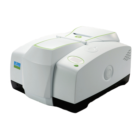
24 . Frontier IR Dual-Range Systems User's Guide A Guided Tour of the Frontier IR Dual-Range Spectrometers PerkinElmer Frontier IR Dual-Range spectrometers are bench-top FT-IR instruments (Figure 3). Fully optimized performance is achieved by the provision of dual beamsplitters, dual sources (Frontier FT-IR/FT-NIR only) and dual detectors. -
Page 25: Configuration Changes
An Overview of the Frontier IR Dual-Range Spectrometers . 25 The instrument is connected to a PC, either point-to-point or over a network. The Spectrum software package supplied enables you to control the instrument and to manipulate the spectra that you collect. -
Page 26: Top Panel Controls
Either one removes water vapor; however, nitrogen is preferable because it also removes atmospheric carbon dioxide. Do not use a flammable gas to purge the Frontier IR instruments. The instrument contains a hot source, and a fire or explosion will result. Only use clean, dry, oil-free nitrogen or air to purge the instrument. -
Page 27: The Sample Compartment
An Overview of the Frontier IR Dual-Range Spectrometers . 27 The sample compartment The instrument has a large, purgeable sample compartment (Figure 5) located at the front of the instrument. Sample compartment lid Baseplate Figure 5 Frontier IR sample compartment... -
Page 28: Internal Accessories
28 . Frontier IR Dual-Range Systems User's Guide Internal accessories A wide range of optional MIR and NIR accessories, such as the Universal ATR accessory, fit in the sample compartment (Figure 6). Figure 6 Frontier IR with Universal ATR accessory Appendix 1: It is easy to remove an internal accessory and to replace it with another. -
Page 29: The Spotlight 400 Series Imaging System
An Overview of the Frontier IR Dual-Range Spectrometers . 29 Do not attempt to remove the external accessory bracket mounted within the handhold on the right of the instrument or to transfer the bracket to another spectrometer. CAUTION The external accessory bracket is fitted by a PerkinElmer Service Engineer, along with any other internal components that may be required. -
Page 30: Sample Compartment Windows
30 . Frontier IR Dual-Range Systems User's Guide Sample compartment windows The Frontier FT-IR/FT-NIR instrument has KBr windows fitted in the sample compartment. It is possible to change the sample compartment windows if they are not suitable for your Installing/Replacing Beam Port and application. -
Page 31: Accessories For The Frontier Ir Spectrometer
Figure 10 Frontier IR spectrometer with Universal ATR and External NIRA accessories There is a range of specialized sampling accessories available for the Frontier IR instruments, as shown in Table 1. Table 1 Sampling accessories for the Frontier IR instruments... - Page 32 *The NIR Tablet Autosampler accessory is supported by AssureID software and Spectrum software version 6.x. It is not supported in Spectrum software version 10.0 or later. ** For more details of the GPOB options, contact your PerkinElmer Sales Representative. IR & Raman...
-
Page 33: Frontier Ir Sytems Upgrades
An Overview of the Frontier IR Dual-Range Spectrometers . 33 Frontier IR Sytems Upgrades The Frontier IR systems are designed to be flexible, upgradable instruments. The upgrades available for Frontier IR Dual-Range Systems are listed in Table 2. Table 2 Frontier IR Dual-Range Systems Upgrades... - Page 34 34 . Frontier IR Dual-Range Systems User's Guide...
-
Page 35: Unpacking And Installation
Unpacking and Installation... -
Page 36: Requirements
They contain important information. Electrical requirements The Frontier IR instruments can operate on electricity supplies of 50 or 60 Hz and in the 100 V to 230 V range without any adjustment. The nominal power consumption of the instrument is 120 VA. -
Page 37: Unpacking The Spectrometer
Unpacking and Installation . 37 Unpacking the spectrometer The Frontier IR spectrometer is a heavy precision instrument, so two people are required for safe handling. The instrument weighs approximately 36 kg unpacked (40 kg packed) WARNING and has a lifting recess on either side. Consult the local codes of practice issued by safety advisors before attempting to lift it. - Page 38 Frontier FT-IR/FT-NIR Beamsplitter Kit (as applicable) L1250438 Frontier FT-IR/FT-FIR Beamsplitter Kit (as applicable) If any items are missing or damaged, contact your local PerkinElmer office. 2. Carefully remove the instrument from the shipping container, but not from the bag in which it was shipped.
-
Page 39: The Desiccant Indicator
Unpacking and Installation . 39 The Desiccant Indicator The optical system of the spectrometer is purged at the factory. This protects the beam port windows (and, once fitted, the beamsplitters) from being damaged by humidity. Replaceable packs of desiccant keep the optics dry and free of CO The top panel of the instrument includes a desiccant indicator, whose sectors change sequentially from blue to pink as the desiccant becomes exhausted (Figure 11). -
Page 40: Connecting Up The Spectrometer
40 . Frontier IR Dual-Range Systems User's Guide Connecting up the Spectrometer Connecting to the PC NOTE: To control your instrument from a PC, use the crossover cable supplied. To control your instrument over your network, use a standard Ethernet cable (not supplied). -
Page 41: Other Connectors
Unpacking and Installation . 41 Other connectors The communication ports for peripheral devices are shown in Figure 13. Instrument purge 10101 Spt. Lt. Sample area purge EXT.R Figure 13 Communication ports Legends and icons that identify the function of each of the ports are printed on the hinge molding directly above the port. -
Page 42: Connecting The Spectrometer To The Electrical Supply
42 . Frontier IR Dual-Range Systems User's Guide Icon Description Connector Voltages Maximum Type Currents EXT.R Right external detector module. 15 way +12 V 0.65 A Connects to an external detector high density module. Usually the detector is D-type −12 V 0.65 A... - Page 43 Unpacking and Installation . 43 Frontier IR instruments can operate on electricity supplies of 50 or 60 Hz and in the 100 V to 230 V range without any adjustment. 1. Fit the molded socket of the power cable into the electrical supply inlet (Figure 14) of the instrument.
-
Page 44: Installing The Instrument In The Software
44 . Frontier IR Dual-Range Systems User's Guide Installing the Instrument in the Software Before you can use the instrument it must be set up in the software. Installing the software NOTE: If you are supplying your own computer, make sure that it meets the minimum requirements for hardware and software set out in the “PC Requirements”... -
Page 45: Using The Spectrometer With Spectrum
Using the Spectrometer with Spectrum... -
Page 46: Basics Of Software Control
To save time, we suggest that you leave the instrument switched on at all times. 2. From the Start menu select Programs; the PerkinElmer Applications group; the Spectrum sub-group and then the Spectrum application. Double-click the shortcut icon on the desktop. -
Page 47: Scanning Samples
The configurable Scan toolbars at the top of the workspace include the tools you need to collect a sample spectrum (Figure 15). Figure 15 Frontier IR Dual-Range systems default scan toolbars By default, the Measurement bar includes Scan, Halt, Background and Monitor buttons. -
Page 48: Changing The Instrument Range
48 . Frontier IR Dual-Range Systems User's Guide 4. If, for any reason, you want to stop scanning your sample, click You can use the Sample Shuttle Accessory (L1200302) to set up an interleaved cycle scan so that you do not have to open the sample compartment between the background and sample scans. -
Page 49: Changing The Beampath
Working with the instrument display and Go button Display Go button Figure 16 Frontier IR top panel controls The display on the front right of the top of your instrument is used to display prompts and other messages generated by Spectrum software. -
Page 50: Using The Spectrum On-Screen Help System
50 . Frontier IR Dual-Range Systems User's Guide To direct the beam to the External NIRA, select Right external from the Beam Location drop-down list. Figure 18 Setup Instrument BeamPath tab with the beampath directed to the External NIRA (circled) -
Page 51: Atmospheric (Co O) Suppression
Using the Spectrometer with Spectrum . 51 Atmospheric (CO O) Suppression Atmospheric suppression can be selected in the Setup Instrument Advanced tab (Figure 19). Figure 19 Setup Instrument Advanced tab in Spectrum What is atmospheric suppression? This is an atmospheric correction routine. This routine is more powerful than simple subtraction, overcoming the following issues: •... - Page 52 52 . Frontier IR Dual-Range Systems User's Guide Figure 21 Atmospheric suppression...
-
Page 53: Avi Correction
Using the Spectrometer with Spectrum . 53 AVI Correction AVI correction can be selected in the Setup Instrument Advanced tab in Spectrum (Figure 19). NOTE: AVI correction is not available when in the FIR range. AVI correction can only be performed if an AVI Calibration has been set up for the current configuration and resolution. -
Page 54: What Does Avi Correction Do
54 . Frontier IR Dual-Range Systems User's Guide What does AVI correction do? When AVI is switched on, the software measures the current instrument profile relative to an absolute standard (the methane cell) and an ideal lineshape function, and applies a correction (Figure 22). -
Page 55: Look Ahead
Using the Spectrometer with Spectrum . 55 Look Ahead Look Ahead can be selected in the Setup Instrument Advanced tab (Figure 19). What is Look Ahead? Look Ahead is a novel system where the spectrometer scans continuously and uses the properties of the measured spectrum to identify changes corresponding to sample removal, sample insertion, or sample change, automatically. -
Page 56: Quality Checks
56 . Frontier IR Dual-Range Systems User's Guide Quality Checks Quality Checks can be selected in the Setup Instrument Advanced tab (Figure 19). What are Quality Checks? Quality checking is a tool for less experienced IR users that identifies possible problems in the spectrum being collected and suggests ways of improving the measurement. -
Page 57: Routine Maintenance
Routine Maintenance... -
Page 58: Cleaning The Spectrometer
58 . Frontier IR Dual-Range Systems User's Guide Cleaning the Spectrometer Clean the outside of the instrument using a damp cloth. If necessary, a mild detergent may be used. Before you clean the entire instrument, always perform a patch test on an inconspicuous area. -
Page 59: Moving The Spectrometer
The spectrometer can be lifted using the shaped handholds on its sides, as shown in Figure 23. Two people are needed to lift it because its basic weight is approximately 36 kg. Lifting handhold, (repeated on left of the instrument) Figure 23 Lifting a Frontier IR spectrometer... -
Page 60: Condensation
The Set Temperature utility A Frontier IR instrument is able to thermostat (that is, control the temperature of) its internal optical bench. By default, this capability is enabled by the PerkinElmer Service Engineer when the instrument is installed. -
Page 61: Replacing The Frontier Ft-Ir/Ft-Fir Sample Compartment Windows
Routine Maintenance . 61 Replacing the Frontier FT-IR/FT-FIR Sample Compartment Windows NOTE: You can also change the sample compartment windows in the Frontier FT-IR/FT-NIR Installing/Replacing Beam Port and Sample spectrometer. For more information, see Compartment Windows on page 85. The sample compartment windows in the Frontier FT-IR/FT-FIR spectrometer need to be changed when moving between the MIR and FIR ranges. - Page 62 62 . Frontier IR Dual-Range Systems User's Guide 5. Fit the window to the sample compartment. Ensure the seal is fully seated and the key on the window lines up with the notch in the main cover (Figure 25). Sample compartment wall...
- Page 63 Routine Maintenance . 63 2. Place each window in the holder, with the seal in place, and tighten the screw using the screwdriver provided. NOTE: Do not over tighten the screw. 3. Close the spare window compartment cover. If you have an MCT detector for the MIR range, you will be supplied with an Attenuator kit (part number L1160560) containing 1%T, 4%T, 6%T, 14%T and 32%T attenuators.
-
Page 64: The Desiccant Indicator In Detail
64 . Frontier IR Dual-Range Systems User's Guide The Desiccant Indicator in Detail The optical system of the spectrometer is purged at the factory. This protects the sample compartment windows, external port windows, or beamsplitters from being damaged by humidity. Replaceable packs of desiccant maintain the purge. -
Page 65: Changing The Desiccant
Routine Maintenance . 65 Changing the Desiccant Expect to change the desiccant spectrometer every six months. in the Old, used desiccant releases moisture. CAUTION In regions experiencing high humidity levels we recommend that you change the desiccant more often. The desiccant change interval is set in the Desiccant change due in (days) option on the Setup Instrument BeamPath tab in Spectrum software (Figure 29). -
Page 66: Renewing The Instrument Desiccant
Do not use damaged packs of desiccant. Make sure that the packs you use have not been left in contact with the air. You can purchase disposable desiccant kits from PerkinElmer (part number N0171159). A kit contains two packs of desiccant, and three kits are required. -
Page 67: Installing Rechargeable Desiccant In The Instrument
Routine Maintenance . 67 4. Open the cover and remove all the exhausted desiccant packs (Figure 32), noting how they are installed. Desiccant compartment (empty) Figure 32 Desiccant removed 5. Place the first three packs of desiccant upright in the recess on the right of the desiccant holder then, one at a time, lay the three remaining packs flat in the upper part of the holder (Figure 33). -
Page 68: Renewing The Desiccant In The Spare Window Compartment
Installing disposable desiccant in the window compartment The desiccated compartment contains two disposable desiccant packs. You can purchase disposable desiccant kits from PerkinElmer (part number N0171159). A kit contains two packs of desiccant, and one kit is required. 1. Inspect the humidity indicator card in the plastic bags in which the spare desiccant packs are packed. - Page 69 Routine Maintenance . 69 Installing rechargeable desiccant in the window compartment There is also a rechargeable desiccant kit available (part number L1251840). Installing disposable To install rechargeable desiccant packs refer to the procedure for desiccant in the window compartment on page 68. The desiccated compartment requires a single rechargeable desiccant pack that is sized to fit the desiccant container.
-
Page 70: Purging The Spectrometer
70 . Frontier IR Dual-Range Systems User's Guide Purging the Spectrometer Under most circumstances, you do not need to purge the optical system. However, after performing any maintenance tasks that involved opening the main cover, you may purge the optical system to remove water vapor and CO that entered while the system was open. - Page 71 Routine Maintenance . 71 1. The tubing is connected to the instrument by a universal pipe fitting which is secured to the tubing with a nut. Two sets of fittings are supplied with the instrument. Assemble the fittings to the tubing as illustrated in Figure 35. Knurled nut Beveled end Tubing...
- Page 72 72 . Frontier IR Dual-Range Systems User's Guide 7. Disconnect the fitting from the instrument by pushing the clip located at the bottom of the purging port (Figure 37). Locking clip Figure 37 Disconnect the locking clip...
-
Page 73: Changing The External Fuse
There is one spare fuse in the fuse drawer. If you need more, order 2 A, 250 V Time Lag fuses (part number 04970839) from PerkinElmer. You must only replace the fuse with one of this type and rating. Do not use makeshift fuses and do not short-circuit fuse holders. - Page 74 74 . Frontier IR Dual-Range Systems User's Guide 1. Lever out the fuse drawer so that it swings down over the power socket. The fuse is in the right hand slot. 2. Remove the old fuse and discard it. 3. Fit the new fuse into the slot (Figure 39).
-
Page 75: Cooling The Mct Detector (If Fitted)
Routine Maintenance . 75 Cooling the MCT Detector (If Fitted) The instrument may be fitted with an MCT (mercury cadmium telluride) detector. When it is fitted in the instrument it must be cooled to 77 K before you collect spectra. The detector is mounted in a dewar that can be filled with liquid nitrogen. - Page 76 76 . Frontier IR Dual-Range Systems User's Guide 1. Remove the MCT coolant cover (Figure 40). MCT coolant cover Figure 40 Location of MCT coolant cover 2. Remove the plug from the dewar. 3. Ensure that the funnel guide, which helps prevent overspill entering the instrument body rather than the dewar, is in place.
- Page 77 NOTE: Cooled detector dewars require pumping down after approximately 12 months operation. When the boil-off rate of liquid nitrogen becomes excessive (that is, the liquid nitrogen level is low after 3–4 hours of operation), consult your PerkinElmer Service Engineer.
- Page 78 78 . Frontier IR Dual-Range Systems User's Guide...
-
Page 79: Advanced Maintenance
Advanced Maintenance... -
Page 80: Opening The Main Cover
80 . Frontier IR Dual-Range Systems User's Guide Opening the Main Cover To perform most maintenance tasks, you have to open the main cover of the spectrometer. Switch off the mains power supply to the spectrometer, wait 60 seconds and disconnect the power cable before you open the cover of the spectrometer. - Page 81 Advanced Maintenance . 81 4. Remove the sample compartment cover, if fitted; open the cover, press on the cover retaining clip and then pull the cover vertically to remove it (Figure 42). Sample cover release clip Figure 42 Removing the sample compartment cover 5.
- Page 82 82 . Frontier IR Dual-Range Systems User's Guide 8. Ensure the cover is fully open and retained by the stay. 9. Perform the necessary maintenance inside the instrument. Figure 45 illustrates the primary component parts of a Frontier IR Dual-Range spectrometer. Laser power supply...
-
Page 83: Replacing A Source
Advanced Maintenance . 83 Replacing a Source Switch off the mains power supply to the spectrometer, wait 60 seconds and disconnect the power cable before you open the cover of the spectrometer. This makes sure that you are safe from electrical shock and laser radiation. - Page 84 84 . Frontier IR Dual-Range Systems User's Guide The source element is brittle and can be broken if not handled properly. Be careful when removing and installing the source. CAUTION Do not touch the glass bulb as this will degrade the performance of the bulb and shorten its life.
-
Page 85: Installing/Replacing Beam Port And Sample Compartment Windows
Advanced Maintenance . 85 Installing/Replacing Beam Port and Sample Compartment Windows The following procedure describes how to install a window in one of the external beam ports. It also applies to installing windows in the sample compartment of the Frontier FT-IR/FT-NIR spectrometer. - Page 86 86 . Frontier IR Dual-Range Systems User's Guide 3. Fit the window to the main cover from the outside in. Ensure the seal is fully seated and the key on the window lines up with the notch in the main cover.
-
Page 87: Installing Filters In The Filter Wheel
Advanced Maintenance . 87 Installing Filters in the Filter Wheel The following procedure describes how to install a filter in the filter wheel. The same procedure should be followed when replacing a filter or the methane cell. The filter wheel assembly is removed from its mounting and placed on the standard sample slide baseplate. - Page 88 88 . Frontier IR Dual-Range Systems User's Guide 3. Install the standard sample holder baseplate, but remove the sample holder itself by unscrewing the knurled screw (Figure 52). Knurled screw Figure 52 Knurled screw 4. To remove the filter wheel, loosen the set screw that secures it to its shaft using a 1.5 mm Allen key (Figure 53) and then gently ease the filter wheel off the shaft,...
- Page 89 Advanced Maintenance . 89 5. Place the assembly face down on the sample holder baseplate. 6. Working clockwise around the filter wheel, identify the next available filter position (Figure 54). Position 5 and Position 7 are available for your custom filters. There is no filter in Position 6 in the Frontier FT-IR/FT-FIR spectrometer.
- Page 90 90 . Frontier IR Dual-Range Systems User's Guide 9. Refit the filter wheel to its spindle and secure it with the set screw. Make sure that you tighten the set screw onto the flat of the shaft. CAUTION If the set screw is tightened onto a round portion of the shaft the filter wheel may loosen.
-
Page 91: Replacing The Laser And Power Supply
Advanced Maintenance . 91 Replacing the Laser and Power Supply Switch off the main power supply to the spectrometer, wait 60 seconds and disconnect the power cable before you open the cover of the spectrometer. This makes sure that you are safe from electrical shock and laser radiation. - Page 92 92 . Frontier IR Dual-Range Systems User's Guide 2. Snip, and remove, the cable tie surrounding the power supply, noting how it secures the laser cables (Figure 57). The laser power supply fixings are accessible from the left of the instrument.
- Page 93 Advanced Maintenance . 93 6. Unhook the spring at the rear of the laser, and remove the two screws on the retaining bracket at the front of the laser (Figure 59). Laser spring retaining pin Laser Laser power supply Laser bracket Baffle retaining retaining screw screw...
- Page 94 94 . Frontier IR Dual-Range Systems User's Guide...
-
Page 95: Appendices
Appendices... -
Page 96: Appendix 1: Changing The Sample Area Accessory
96 . Frontier IR Dual-Range Systems User's Guide Appendix 1: Changing the Sample Area Accessory 1. Remove the sample area cover if fitted by opening the cover, pressing the clip and pulling the cover vertically to remove (Figure 60). Sample... - Page 97 Appendices . 97 3. Install the new accessory (Figure 62) by sliding it onto the ledge and pushing it into the sample compartment until it engages with the connector. Figure 62 Installing a sampling accessory Spectrum automatically recognizes which accessory is installed, and displays the accessory information on the Setup Instrument tabs.
-
Page 98: Appendix 2: Instrument Self-Checks
98 . Frontier IR Dual-Range Systems User's Guide Appendix 2: Instrument Self-Checks NOTE: It can take the instrument about two hours to equilibrate when switched on after being switched off overnight. To save time, we suggest that you leave the spectrometer switched on at all times. - Page 99 Appendices . 99 Initialization errors If your instrument generates one of the following error messages, switch off the instrument, then switch the instrument on again. Consult your PerkinElmer service representative if the problem persists. Error message Action Program Integrity Failed The instrument’s firmware may be corrupt, so must be...
-
Page 100: Appendix 3: Instrument Performance Validation
100 . Frontier IR Dual-Range Systems User's Guide Appendix 3: Instrument Performance Validation The Frontier FT-IR/FT-NIR spectrometer is supplied with NIR Performance Validation Kit (part number L1250405), which contains a polystyrene reference sample. To validate the MIR performance of your instrument, use the optional MIR Performance Validation Kit (part number L1250404). -
Page 101: Appendix 4: Decontamination And Cleaning
(Brussels) 0800 90 66 42 (Monza) If you are located outside of these regions, please call your local PerkinElmer sales office for more information. Cleaning the instrument Exterior surfaces may be cleaned with a soft cloth, dampened with a mild detergent and... -
Page 102: Appendix 5: Weee Instructions For Perkinelmer Products
Customer care department in your region. http://las.perkinelmer.com/OneSource/Environmental-directives.htm Products from other manufacturers may also form a part of your PerkinElmer system. These other manufacturers are directly responsible for the collection and processing of their own waste products under the terms of the WEEE Directive. Please contact these manufacturers directly before discarding any of their products. -
Page 103: Index
Index . 103 Index About this manual ......6 FCC rules and regulations ....22 Accessories ........31 Filter wheel External ........28 Filter ......... 89 Internal ........28 Filter holder ....... 89 Accessory Foam spacer ......89 Changing ......28, 96 Installing filters ...... - Page 104 104 . Frontier IR Dual-Range Systems User's Guide Replacing ........91 Use of flammable solvents and samples Laser safety regulations ....17 ..........15 Lifting points ......... 59 Use of nitrogen ......14 Locking bolts Safety interlock......25 Undoing ........81 Sample area cover Release clip ........
Need help?
Do you have a question about the Frontier IR and is the answer not in the manual?
Questions and answers