Table of Contents
Advertisement
Quick Links
Advertisement
Table of Contents

Related Manuals for PerkinElmer Spectrum 100 Series


Summary of Contents for PerkinElmer Spectrum 100 Series
- Page 1 MOLECULAR SPECTROSCOPY 100 S PECTRUM ERIES User’s Guide...
- Page 2 The information contained in this document is subject to change without notice. Except as specifically set forth in its terms and conditions of sale, PerkinElmer makes no warranty of any kind with regard to this document, including, but not limited to, the implied warranties of merchantability and fitness for a particular purpose.
-
Page 3: Table Of Contents
FCC rules and regulations ............... 21 Use of Flammable Solvents and Samples ..........22 An Overview of the Spectrometers ..........23 A Guided Tour of the Spectrum 100 Series ..........24 Top Panel Controls................. 25 Sample compartment ..............26 Power switch and communications ports .......... 27 Optical system ................ - Page 4 Re-printing the Information on a Certificate........106 When Should I Recalibrate My Instrument ? ........107 Appendices..................109 Appendix 1: Changing the Sampling Accessory........110 Appendix 2: Instrument Self-Checks............. 113 Appendix 3: WEEE Instructions for PerkinElmer Products ....... 115 Index....................116...
-
Page 5: Introduction
Introduction... -
Page 6: About This Manual
6 . Spectrum 100 Series User’s Guide About This Manual This manual contains the following sections: • Introduction; • Warnings and Safety; • An Overview of the Spectrum 100 Series Spectrometers; • Unpacking and Installation; • Using the Spectrum 100 Series Spectrometers; • Routine Maintenance; •... -
Page 7: Conventions Used In This Manual
ALT+F. All eight digit numbers are PerkinElmer part numbers unless stated otherwise. The term ‘instrument’ refers to either the Spectrum 100 FT-IR or Spectrum 100N FT-NIR spectrometer, and any sampling accessory fitted. - Page 8 8 . Spectrum 100 Series User’s Guide We use the term WARNING to inform you about situations that could result in personal injury to yourself or other persons. Details about these circumstances are in a box like this one. WARNING Warning (Warnung) Bedeutet, daß...
-
Page 9: Warning Signs On The Instrument
Introduction . 9 Warning Signs on the Instrument Caution, hot surface. Caution, risk of electric shock. Caution, laser radiation hazard. Caution, risk of danger. Refer to accompanying documents in all cases where this symbol is used to find out the nature of the potential hazard and any actions which have to be taken. - Page 10 10 . Spectrum 100 Series User’s Guide...
-
Page 11: Warnings And Safety Information
Warnings and Safety Information... -
Page 12: Safety Summary
DO keep the instrument dry. Avoid spilling liquid into the instrument. Clean all external spills immediately. If anything that is spilled enters the main body of the instrument, switch off the power and contact a PerkinElmer Service Engineer. DO NOT stare into the internal laser beam under the instrument cover. The instrument contains a low power, visible (red) laser;... -
Page 13: General Safety
General Safety The Spectrum 100 FT-IR and Spectrum 100N FT-NIR spectrometers have been designed and tested in accordance with PerkinElmer specifications and in accordance with the safety requirements of the International Electrotechnical Commission (IEC). The instruments conform to IEC publication 61010-1 (‘Safety requirements for electrical equipment for measurement, control, and laboratory use’) as it applies to IEC Class 1... -
Page 14: Location And Ventilation
14 . Spectrum 100 Series User’s Guide Location and ventilation To allow for adequate cooling, the instrument should not be sited near to room heating equipment, for example, central heating radiators. During operation, there should be a minimum gap of: •... - Page 15 Warnings and Safety Information . 15 The instrument has: • An IEC Pollution Degree 2 classification - usually only non–conductive atmospheric pollution of the equipment occurs; occasionally, however, a temporary conductivity caused by condensation must be expected. • An IEC Insulation class I rating for external circuits – only connect equipment that meets the requirements of IEC 61010-1, IEC 60950 or equivalent standards.
-
Page 16: Laser Safety Regulations
16 . Spectrum 100 Series User’s Guide Laser Safety Regulations The Spectrum 100 FT-IR and Spectrum 100N FT-NIR spectrometers are CDRH Class I, BS EN 60825-1/IEC 60825-1 Class 1 laser products. The optical module contains a Class II/2 Helium Neon (HeNe) laser, which emits visible, continuous wave radiation at a wavelength of 633 nm and has a maximum output power of 1 mW. -
Page 17: Explanation Of The Laser Radiation Hazard And Its Classification
Warnings and Safety Information . 17 Explanation of the laser radiation hazard and its classification Indirect observation of the laser beam radiation in the optical path is not hazardous. Directly viewing the laser beam along its axis (allowing the laser beam radiation to pass into the eye) can be hazardous, depending upon the power of the beam, the length of time that the eye is exposed to the beam and the optical efficiency of the exposed eye. -
Page 18: Laser Apertures
18 . Spectrum 100 Series User’s Guide Laser Apertures The accessible Class I/Class 1 laser radiation emerges from the aperture in the left hand side of the sample compartment; the radiation crosses the sample compartment and enters the detector aperture. -
Page 19: Labels
Figure 1 Labels (rear of instrument) NOTE: The label with a crossed-out wheeled bin symbol and a rectangular bar indicates that the product is covered by the Waste Electrical and Electronic Equipment (WEEE) Directive. Refer to Appendix 3: WEEE Instructions for PerkinElmer Products. -
Page 20: Product Identification Label
20 . Spectrum 100 Series User’s Guide Serial Number and Date of Manufacture NOTE: There is a second copy of the CAUTION label inside the cover. Figure 2 Labels (sample area) Product identification label Figure 3 Product label (front of instrument) -
Page 21: Emc Compliance
Warnings and Safety Information . 21 EMC Compliance EC directive The Spectrum 100 FT-IR and Spectrum 100N FT-NIR spectrometers have been designed and tested to meet the requirements of the EC Directive 89/336/EEC. The instruments comply with the EMC standard EN 61326-1 (EMC standard for electrical equipment for measurement, control and laboratory use). -
Page 22: Use Of Flammable Solvents And Samples
22 . Spectrum 100 Series User’s Guide Use of Flammable Solvents and Samples The instrument contains a hot source and contact with flammable vapors may cause an explosion. When working with flammable solvents or samples, particularly during unattended operation with... -
Page 23: An Overview Of The Spectrometers
An Overview of the Spectrometers... -
Page 24: A Guided Tour Of The Spectrum 100 Series
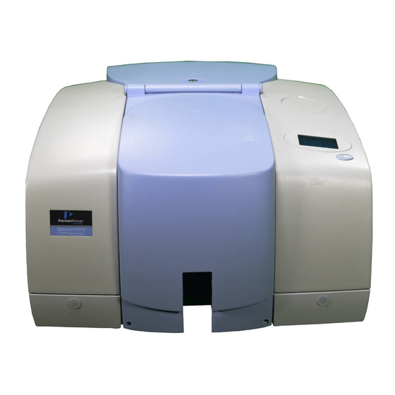
24 . Spectrum 100 Series User’s Guide A Guided Tour of the Spectrum 100 Series Figure 4 The Spectrum 100 Series spectrometers The PerkinElmer Spectrum 100 Series spectrometers (Figure 4) are bench-top instruments that provides all the following in one self-contained unit: •... -
Page 25: Top Panel Controls
An Overview of the Spectrometers . 25 Top Panel Controls Display Go button Figure 5 Top Panel Controls The Display on the lower right of the top of your instrument has two purposes: 1. To display messages generated by the instrument’s firmware, such as those that monitor initialization and diagnostics when the instrument is switched on. -
Page 26: Sample Compartment
26 . Spectrum 100 Series User’s Guide Sample compartment The sample compartment (Figure 6) is located at the front of the instrument. You open the sample compartment by lifting the cover using the recess at the front. Figure 6 Sample compartment •... -
Page 27: Power Switch And Communications Ports
An Overview of the Spectrometers . 27 Power switch and communications ports The power switch, AC power cable connector, and communications ports are on the rear of the instrument. The power switch is marked I/O (on/off). NOTE: It can take the Spectrum 100 FT-IR and Spectrum 100N FT-NIR spectrometers up to two hours to equilibrate when switched on after being switched off overnight. -
Page 28: Accessories For The Spectrum Instrument
28 . Spectrum 100 Series User’s Guide Accessories for the Spectrum instrument There is a range of specialized sampling accessories available for the Spectrum 100 FT-IR and Spectrum 100N FT-NIR spectrometers, including: Accessory Spectrum 100 FT-IR Spectrum 100N FT-NIR Sample Shuttle... -
Page 29: Unpacking And Installation
Unpacking and Installation... -
Page 30: Requirements
30 . Spectrum 100 Series User’s Guide Requirements NOTE: Read the warnings and safety information at the start of this manual before you install the instrument. They contain important information. Electrical requirements The Spectrum 100 FT-IR and Spectrum 100N FT-NIR spectrometers can operate on electricity supplies of 50 or 60 Hz and in the 100 to 230 V range without any adjustment. -
Page 31: Unpacking The Spectrometer
Spectrum 100 Series Getting Started Guide L1050002 Spectrum 100/100N Manuals CD L1050005 Spectrum Multimedia CD. L1242701 NIR Source L1240055 Cuvette Holder Assembly L1240056 Cell Holder Assembly and disposable cells (5). If any items are missing or damaged, contact your local PerkinElmer office. - Page 32 32 . Spectrum 100 Series User’s Guide 2. Carefully remove the instrument from the shipping container, but not from the bag in which it was shipped. The spectrometer must be allowed to reach the temperature of its surroundings before it is removed from the bag. This means leaving it...
-
Page 33: The Desiccant Indicator
Unpacking and Installation . 33 The Desiccant Indicator The optical system of the spectrometer is purged at the factory. This protects the beamsplitter and the sample compartment windows from being damaged by humidity. Replaceable packs of desiccant keep the optics dry and free of CO The top panel of the instrument includes a Desiccant Indicator, whose sectors change sequentially from blue to pink as the desiccant packs are exhausted. -
Page 34: Connecting Up The Spectrometer
34 . Spectrum 100 Series User’s Guide Connecting up the Spectrometer Connecting to the PC NOTE: To control your instrument from a PC, use the crossover cable supplied. To control your instrument over your network, use a standard Ethernet cable (not supplied). -
Page 35: Other Connectors
Unpacking and Installation . 35 Other connectors The communications ports for peripheral devices are illustrated in Figure 10. A.U.I. Instrument purge Sample area purge |0|0 EXT.R Figure 10 Communications ports Icons which identify the function of each of the communications ports are printed on the hinge molding directly above the communications port. - Page 36 36 . Spectrum 100 Series User’s Guide Icon Description Connector Voltages Maximum Type Currents Keyboard. Connects a keyboard or Mini-DIN +5 V 0.65 A barcode reader to the spectrometer. 6-way Serial port. Connects a PC to the 9-way +12 V <...
-
Page 37: Connecting The Spectrometer To The Electrical Supply
Unpacking and Installation . 37 Connecting the Spectrometer to the electrical supply The power cable for the electrical supply plugs into the rear of the instrument. It has a molded socket at one end. If it is necessary to fit a plug on the power cable, use the wire color code below: Plug Pin Wire Color (100-120 V) -
Page 38: Installing The Spectrum Software
38 . Spectrum 100 Series User’s Guide Installing the Spectrum Software Before setting up the instrument, set up your PC and install the Spectrum software. Minimum PC requirements If you are supplying your own computer, make sure that it meets the minimum... -
Page 39: The Instrument Install Wizard
Unpacking and Installation . 39 The Instrument Install Wizard NOTE: Install your instrument with the standard sample slide fitted, rather than any additional accessory, such as a Universal ATR (for the Spectrum 100 FT-IR) or the NIR Tablet Autosampler (for the Spectrum 100N FT-NIR). Accessories are shipped in separate boxes and fitted later. - Page 40 40 . Spectrum 100 Series User’s Guide 3. Click Next. The Instrument Details page is displayed. 4. Enter an Instrument Name, which will be used by the Spectrum software to identify your instrument. 5. If the instrument is connected to your network enter a suitable IP Address, which can be provided by your network administrator.
- Page 41 Unpacking and Installation . 41 6. Click Next. The Instrument Configuration Disk page is displayed, which prompts for the <name>.cfg of the configuration file required by your instrument. This file is shipped on a CD with your instrument. If a suitable configuration file has been has been installed on your PC on a previous occasion, this dialog is amended to enable you either to Use Existing Configuration, or to Overwrite Configuration.
- Page 42 42 . Spectrum 100 Series User’s Guide 7. Browse to the configuration file, then click Copy Configuration. The Test Configuration page is displayed. This test automatically checks whether your PC and instrument can communicate with each other. Assuming this Connection is working, the page then displays the Serial Number...
- Page 43 Unpacking and Installation . 43 9. Remove the configuration CD and click Next. The wizard now offers the opportunity to Test the performance of your instrument. 10. If you want to continue with the performance tests, click Next. Otherwise, click Skip.
- Page 44 44 . Spectrum 100 Series User’s Guide The Spectrum Software works through a series of instrument performance tests: • Start-up – Reviews the power-up diagnostics to make sure no problems were found when the Spectrum instrument was switched on. •...
- Page 45 Unpacking and Installation . 45 12. Click Next. If your instrument is an FT-IR Spectrometer, the wizard now offers the opportunity to Collect ASTM Reference Spectra, which are used when ASTM validation tests are performed. For more information about ASTM level 0 tests, see the HTML Help for the Spectrum software.
- Page 46 46 . Spectrum 100 Series User’s Guide 13. To collect ASTM Reference Spectra, click Next. 14. When the ASTM0 Reference Spectra collection is complete, click View Log. A new window allows you to see the results in more detail. If you want to view the results later, the log is stored at C:\Program Files\PerkinElmer\ServiceIR\<Instrument Serial Number>\PerformanceTests...
- Page 47 Unpacking and Installation . 47 15. Click Next. The Finish page is displayed. This page of Instrument install wizard offers a summary of the Configuration and Performance Tests. You can also click View Log to see the results of the configuration and performance tests in more detail.
-
Page 48: Using The Instrument Install Wizard To Install An Accessory
48 . Spectrum 100 Series User’s Guide Using the Instrument Install Wizard to install an Accessory The Instrument Install Wizard tests your accessory (against, for example, any shipping damage) and makes sure that any data necessary for its operation is present on your system. - Page 49 Unpacking and Installation . 49 3. Select the instrument on which the accessory will be installed, then click Next. The Install Accessories page is displayed. Some accessories (such as the Universal ATR), but not all, are shipped with a disk containing, for example, reference spectra generated during manufacture.
- Page 50 50 . Spectrum 100 Series User’s Guide 4. Click Next. The Insert Accessory dialog is displayed. 5. Fit the accessory to be installed in the instrument as described in its User’s Guide, Spectrum 100/100N Manuals CD (L1050002) which is provided on the...
- Page 51 View Log. A new window allows you to see the results in more detail. If you want to view the results of the accessories tests later, the log is stored at C:\Program Files\PerkinElmer\ServiceIR\<Instrument Serial Number>\PerformanceTests xxx\PerformanceTests.Log (where xxx is an...
- Page 52 52 . Spectrum 100 Series User’s Guide 10. Click Next. The Finish page is displayed. 11. Click Finish to close the Instrument Install Wizard.
-
Page 53: Using The Spectrometer
Using the Spectrometer... -
Page 54: Basics Of Software Control
1. Switch on the power to the instrument, using the switch above the power cable. 2. From the Start menu select Programs; the PerkinElmer Applications group; the Spectrum sub-group and then the Spectrum application. After the Spectrum start-up splash-screen a dialog is displayed; this may require login details: Enter your User name and Password, if necessary, then click OK. -
Page 55: Controlling The Instrument
Using the Spectrometer . 55 Controlling the Instrument You start scans and make adjustments to the instrument using commands in the Spectrum software. NOTE: The level of control you have (and the complexity of the dialogs you see) is determined by your user level as set on the Instrument tab of the Options dialog, available from the Setup menu. - Page 56 56 . Spectrum 100 Series User’s Guide • Select the Range, Scan type, Units and Scan number (number of scans) on the Scan tab. • Select the instrument settings required on the Instrument tab. The Advanced options of CO2/H2O suppression, AVI correction, Look...
- Page 57 Using the Spectrometer . 57 • Set up items on the beampath on the Beam tab. The Beam tab utilizes an interactive graphic. Hover over its icons to identify elements in the instrument beam path. Where appropriate, right-click for further detail about, or an options dialog for, the element. •...
- Page 58 58 . Spectrum 100 Series User’s Guide 2. When you are satisfied with the entries on the Scan and Instrument Setup dialog tabs, click Start. The Scan Progress dialog opens. If, for example, the instrument resolution setting has been increased, a valid background spectrum may not be available.
-
Page 59: Working With The Instrument Display And Go Button
Using the Spectrometer . 59 5. If Quality Checks have been set, the selected tests are performed as each spectrum is collected, and a signal light (green , amber , or red ) is placed in the QC column to indicate its status. To examine Quality Check results in more detail, select the appropriate scan then click the button. -
Page 60: Using The Spectrum On-Screen Help System
60 . Spectrum 100 Series User’s Guide Using the Spectrum on-screen help system Use the Spectrum HTML Help system to find further information about using Spectrum software to control, set up and adjust your instrument. To open the Help file, select Contents and Index from the Help menu. This menu also includes links to on-screen tutorials (Learning Spectrum), a simplified interface (IR Assistant), and information about the software (About). -
Page 61: Atmospheric (Co O) Suppression
Using the Spectrometer . 61 Atmospheric (CO O) Suppression Atmospheric suppression can be set in the Advanced section on the Instrument tab of the Scan and Instrument Setup dialog. What is atmospheric suppression? This is an atmospheric correction routine. This routine is more powerful than simple subtraction, overcoming the following issues: •... - Page 62 62 . Spectrum 100 Series User’s Guide Figure 14 Atmospheric suppression...
-
Page 63: Avi Correction
Using the Spectrometer . 63 AVI Correction AVI correction can be set in the Advanced section on the Instrument tab of the Scan and Instrument Setup dialog. NOTE: AVI correction uses a methane gas cell installed in the filterwheel. AVI correction is only available on the Instrument tab if this cell has been fitted. -
Page 64: Look Ahead
64 . Spectrum 100 Series User’s Guide Look Ahead Look Ahead can be set in the Advanced section on the Instrument tab of the Scan and Instrument Setup dialog. What is Look Ahead? Look Ahead is a novel system where the spectrometer scans continuously and uses the properties of the measured spectrum to identify changes corresponding to sample removal, sample insertion, or sample change, automatically. -
Page 65: Quality Checks
Using the Spectrometer . 65 Quality Checks Quality Checks can be set in the Advanced section on the Instrument tab of the Scan and Instrument Setup dialog. What are Quality Checks? Quality checking is a tool for less experienced IR users that identifies possible problems in the spectrum being collected and suggests ways of improving the measurement. - Page 66 66 . Spectrum 100 Series User’s Guide...
-
Page 67: Routine Maintenance
Routine Maintenance... -
Page 68: Cleaning The Spectrometer
68 . Spectrum 100 Series User’s Guide Cleaning the Spectrometer Clean the outside of the instrument using a damp cloth. If necessary, a mild detergent may be used. Before you clean the entire instrument, always perform a patch test on an inconspicuous area. -
Page 69: Moving The Spectrometer
The spectrometer can be lifted using the shaped handholds on its sides, as shown in Figure 16. Two people are needed to lift it because its basic weight is approximately 34 kg. Figure 16 Spectrum 100 Series lifting points Condensation Be aware that condensation caused by moving your spectrometer from a cooler environment to a warmer one can damage the windows of the sample compartment. -
Page 70: The Desiccant Indicator In Detail
70 . Spectrum 100 Series User’s Guide The Desiccant Indicator in detail The optical system of the spectrometer is purged at the factory. This protects the KBr (Spectrum 100) or CaF (Spectrum 100N) beamsplitters and the sample compartment windows from being damaged by humidity. Replaceable packs of desiccant maintain the purge. -
Page 71: Changing The Desiccant
Routine Maintenance . 71 Changing the Desiccant NOTE: We recommend that you change the desiccant in the spectrometer before using it for the first time. Expect to change the desiccant every six in the spectrometer months. Old, used desiccant releases moisture. CAUTION In regions experiencing high humidity levels we recommend you change the desiccant more often. -
Page 72: Resetting The Desiccant Change Interval
72 . Spectrum 100 Series User’s Guide Resetting the desiccant change interval The message displayed to warn you that the desiccant in your instrument needs changing (Figure 18) is displayed until the Desiccant options are reset using the Maintenance tool in the Adjustment Toolbox. -
Page 73: Renewing The Disposable Desiccant
Do not use damaged packs of desiccant. Make sure that the packs you use have not been left in contact with the air. You can purchase disposable desiccant kits from PerkinElmer (Part Number N017 1159). A kit contains two packs of desiccant, and three kits are required. - Page 74 74 . Spectrum 100 Series User’s Guide Desiccant Indicator Sample cover release clip Figure 19 Removing the sample area cover 3. Undo the two captive screws securing the desiccant cover (Figure 20). Screw Screw Figure 20 Captive screws securing desiccant cover 4.
-
Page 75: Installing Rechargeable Desiccant
Routine Maintenance . 75 5. Place the first three packs of desiccant upright in the recess on the right of the desiccant holder then, one at a time, lay the three remaining packs flat in the upper part of the holder (Figure 22). Figure 22 Stowing the desiccant packs Ensure that when the packs have been installed they do not rise above the level of the black rubber purge seal. -
Page 76: Purging The Spectrometer
76 . Spectrum 100 Series User’s Guide Purging the Spectrometer Under most circumstances, you do not need to purge the optical system. However, after performing any maintenance tasks that involved opening the main cover, you may purge the optical system to remove water vapor and CO that entered while the system was open. - Page 77 Routine Maintenance . 77 1. The tubing is connected to the instrument by a universal pipe fitting which is secured to the tubing with a nut. Two sets of fittings are supplied with the instrument. Assemble the fittings to the tubing as illustrated in Figure 23. Knurled nut Beveled end of connector...
- Page 78 78 . Spectrum 100 Series User’s Guide 7. Disconnect the fitting from the instrument by pushing the locking clip located on the side of the purging port (Figure 25). Locking Clip Figure 25 Disconnect the locking clip...
-
Page 79: Changing The External Fuse
There is one spare fuse in the fuse drawer. If you need more, order 2A, 250V Time Lag fuses (0497 0839) from PerkinElmer. You must only replace the fuse with one of this type and rating. Do not use makeshift fuses and do not short-circuit fuse holders. - Page 80 80 . Spectrum 100 Series User’s Guide 3. Fit the new fuse into the slot (Figure 27). Fuse Spare Fuse Fuse Drawer Figure 27 Fuse fitted; drawer open 4. Close the drawer. The new fuse is now installed. 5. Reconnect the power cable and switch on the instrument.
-
Page 81: Cooling The Mct Detector (Spectrum 100)
Routine Maintenance . 81 Cooling the MCT Detector (Spectrum 100) Optionally, the Spectrum 100 may be fitted with an MCT (mercury cadmium telluride) detector. When it is fitted in the instrument it must be cooled to 77 K before you collect spectra. - Page 82 82 . Spectrum 100 Series User’s Guide 4. Make sure the supplied plastic funnel is dry. Stand where you can see the inside of the funnel as you pour the nitrogen in. Pour slowly, so that neither the funnel nor the dewar overflows.
-
Page 83: Advanced Maintenance
Advanced Maintenance... -
Page 84: Opening The Main Cover
84 . Spectrum 100 Series User’s Guide Opening the Main Cover To perform most maintenance tasks, you have to open the main cover of the spectrometer. Switch off the mains power supply to the spectrometer, wait 60 seconds and disconnect the power cable before you open the cover of the spectrometer. - Page 85 Advanced Maintenance . 85 Sample Cover Release Clip Figure 30 Removing the sample area cover 5. Remove the fitted sampling accessory, by pulling the blue release handle towards you and sliding the accessory towards you (Figure 31). Sampling Accessory Release Handle Figure 31 Removing the sampling accessory 6.
- Page 86 7. Lift the main cover from the front. 8. Ensure the cover is fully open and retained by the stay. 9. Perform the necessary maintenance inside the instrument. Figure 33 illustrates the primary component parts of a Spectrum 100 Series spectrometer. Power...
-
Page 87: Replacing The Source
Advanced Maintenance . 87 Replacing the Source Switch off the mains power supply to the spectrometer, wait 60 seconds and disconnect the power cable before you open the cover of the spectrometer. This makes sure that you are safe from electrical shock and laser radiation. - Page 88 88 . Spectrum 100 Series User’s Guide 2. Slacken the two terminal screws (Figure 35) securing the wires leading to the source. Disconnect the wires from the connectors. 3. By grasping the round metal source body NOT the wires, remove the source from its housing by pulling, noting its installed position.
-
Page 89: Replacing The Beamsplitter
Advanced Maintenance . 89 Replacing the Beamsplitter Switch off the mains power supply to the spectrometer, wait 60 seconds, and disconnect the power cable before you open the cover of the spectrometer. This makes sure that you are safe from electrical shock and laser radiation. - Page 90 90 . Spectrum 100 Series User’s Guide 3. Remove the beamsplitter retaining screw. 4. Noting its installed position, pull out the beamsplitter. 5. Install the new beamsplitter and secure with the retaining screw. 6. Refit the laser baffle and secure with retaining screws.
-
Page 91: Installing/Replacing Windows
Advanced Maintenance . 91 Installing/Replacing Windows The following procedure describes how to install a window in one of the external beam ports. The details apply equally to windows in the sample compartment. Switch off the mains power supply to the spectrometer, wait 60 seconds, and disconnect the power cable before you open the cover of the spectrometer. - Page 92 92 . Spectrum 100 Series User’s Guide 3. Fit the window to the main cover from the outside in. Ensure the seal is fully seated and the key on the window lines up with the notch in the main cover.
-
Page 93: Installing Filters In The Filterwheel
Advanced Maintenance . 93 Installing Filters in the Filterwheel The following procedure describes how to install a filter in the filterwheel. The same procedure should be followed when replacing a filter. Due to the restricted cabling, the filterwheel assembly is removed from its mounting and placed on the sample compartment baseplate. - Page 94 94 . Spectrum 100 Series User’s Guide 3. Remove the filterwheel assembly from its mounting by undoing and removing the two securing screws (Figure 42). Screw Screw Figure 42 Filterwheel assembly securing screws 4. Place the assembly on the sample accessory baseplate (Figure 43).
- Page 95 Advanced Maintenance . 95 7. Secure the filter to the filterwheel by clipping the holder into place (Figure 45). Align the notches of the holder with the indents in the filterwheel, then twist the holder clockwise to lock it. Filter holder Figure 45 Installing the filter holder 8.
-
Page 96: Installing An Avi Cell In The Filterwheel Assembly
96 . Spectrum 100 Series User’s Guide Installing an AVI Cell in the Filterwheel Assembly Switch off the mains power supply to the spectrometer, wait 60 seconds and disconnect the power cable before you open the cover of the spectrometer. This makes sure that you are safe from electrical shock and laser radiation. -
Page 97: Replacing The Laser And Power Supply
Advanced Maintenance . 97 Replacing the Laser and Power Supply Switch off the main power supply to the spectrometer, wait 60 seconds and disconnect the power cable before you open the cover of the spectrometer. This makes sure that you are safe from electrical shock and laser radiation. - Page 98 98 . Spectrum 100 Series User’s Guide 6. Install the new laser and power supply. Ensure the laser is pushed fully home to the stop at the front of the housing. Screw Screw Laser bracket retaining screw Laser bracket retaining screw...
-
Page 99: Instrument Performance Validation
Instrument Performance Validation... -
Page 100: Performance Validation Kits
100 . Spectrum 100 Series User’s Guide Performance Validation Kits The Spectrum 100N is supplied with Performance Validation kit L1180479, which contains a 35 µm polystyrene reference sample and an NG11 Schott Glass reference sample. For the Spectrum 100, Performance Validation kit L1365335 is available. This kit contains a 1.2 mm polystyrene reference sample. -
Page 101: Validating Instrument Calibration
Instrument Performance Validation . 101 Validating Instrument Calibration In order to validate instrument calibration, tests must be performed under the same measurement conditions as those used to calibrate the Traceable Reference Material (TRM) at the factory. We also recommend that before starting the calibration, you make sure that the Aligning the Instrument instrument is optimally aligned. -
Page 102: Printing The Certificate Of Performance Validation
102 . Spectrum 100 Series User’s Guide Printing the Certificate of Performance Validation Hardware and software requirements To print a certificate you will need a PC running Microsoft Windows, connected to a printer with the correct print drivers installed. The PC does not have to be the one connected to your instrument. - Page 103 Instrument Performance Validation . 103 7. Make sure that the Validation Details are correct, and add any missing information. NOTE: The serial number of your instrument is usually printed on a silver label in the lower sample compartment area. The serial number of the TRM is on the TRM sample holder.
-
Page 104: Possible Reasons For Validation Failure
The incorrect J-stop aperture was used (most often seen at high wavenumbers); The resolution used for collecting the two spectra was not the same. If you need more help, contact your nearest PerkinElmer agent or office. Printing the Certificate Testing for paper orientation Before you print the certificate, you must find the correct orientation for the certificate. - Page 105 Instrument Performance Validation . 105...
-
Page 106: Re-Printing The Information On A Certificate
106 . Spectrum 100 Series User’s Guide 3. Sign the certificate. Keep the spectra trmpic.sp and ipvpic.sp as a record of the original data for future reference. NOTE: The values on the certificate above are for illustration only. Do not use these values for validation of your instrument. -
Page 107: When Should I Recalibrate My Instrument
Instrument Performance Validation . 107 When Should I Recalibrate My Instrument ? When using a Fourier Transform spectrometer, the error in the peak positions will be proportional to the wavenumber. The calibration can be adjusted by changing the effective wavenumber of the HeNe laser. If the peak positions in a spectrum collected ±... - Page 108 108 . Spectrum 100 Series User’s Guide...
-
Page 109: Appendices
Appendices... -
Page 110: Appendix 1: Changing The Sampling Accessory
110 . Spectrum 100 Series User’s Guide Appendix 1: Changing the Sampling Accessory 1. Remove the sample area cover if fitted by opening the cover, pressing the clip and pulling the cover vertically to remove (Figure 50). Sample Cover Release Clip... - Page 111 Appendices . 111 2. Remove the current sampling accessory by pulling the blue release handle (under the baseplate of the accessory) towards you and then sliding the accessory towards you (Figure 51). Release handle Figure 51 Removing the sampling accessory 3.
- Page 112 112 . Spectrum 100 Series User’s Guide 4. The Scan and Instrument Setup dialog automatically recognizes which accessory is installed. Figure 53 UATR Accessory icons...
-
Page 113: Appendix 2: Instrument Self-Checks
Spectrum 100 Series User’s Guide . 113 Appendix 2: Instrument Self-Checks NOTE: It can take the Spectrum 100 FT-IR and Spectrum 100N FT-NIR spectrometers up to 2 hours to equilibrate when switched on after being switched off overnight. To save time, we suggest that you leave the spectrometer switched on at all times. - Page 114 114 . Spectrum 100 Series User’s Guide Initialization Errors If your instrument generates one of the following error messages, switch off the instrument, then switch the instrument on again. Consult your PerkinElmer service representative if the problem persists. Error message Action The instrument’s firmware may be corrupt, so must be...
-
Page 115: Appendix 3: Weee Instructions For Perkinelmer Products
0800 90 66 42 (Monza) Products from other manufacturers may also form a part of your PerkinElmer system. These other manufacturers are directly responsible for the collection and processing of their own waste products under the terms of the WEEE Directive. Please contact these manufacturers directly before discarding any of their products. -
Page 116: Index
116 . Spectrum 100 Series User’s Guide Index Filter........... 94 Filter Holder ........94 Foam Spacer ........94 Installing AVI Cell ........ 96 About This Manual Installing Filters......93, 96 Accessory Location ..........93 Changing........50, 110 Retaining Screws ......... 94 Release Handle........ - Page 117 Spectrum 100 Series User’s Guide . 117 liquid nitrogen........81 Source WARNING..........81 high operating temperature ....87 Multimedia CD 6 Location ..........87 Replacing ........87, 114 Terminal Screws ........88 Spectrum NPL Standard Commands ..........55 Spectrum 100 and 100N Accessories ..........28 Capacitors ...........14 Optical System Cleaning ..........68...
- Page 118 118 . Spectrum 100 Series User’s Guide...
Need help?
Do you have a question about the Spectrum 100 Series and is the answer not in the manual?
Questions and answers