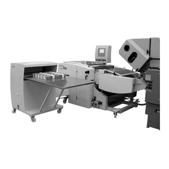
Palamides delta 151 Manual Instruction

Palamides delta 151 Manual Instruction

Automatic delivery

Advertisement

M a n u a l I n s t r u c t i o n
Model 151
April 2005
palamides GmbH
Benzstraße 14 – 71272 Renningen
Tel: +49 (0) 7159 / 92570-0 – Fax +49 (0) 7159 / 92570-99
www.palamides.de
1

Advertisement

Table of Contents
loading

Summary of Contents for Palamides delta 151

  • Page 1 M a n u a l I n s t r u c t i o n Model 151 April 2005 palamides GmbH Benzstraße 14 – 71272 Renningen Tel: +49 (0) 7159 / 92570-0 – Fax +49 (0) 7159 / 92570-99...
  • Page 3: Table Of Contents

    Contents How it works ........................7 Technical Data ........................9 Fundamental Safety Advice ....................11 Machine installation......................13 Description of the machine parts..................16 Handling and Operation ....................20 Setting up the machine....................27 Optimisation menu ......................43 Quick set-up ........................46 10 Quick Check ........................47 11 Sensors, Pneumatics, Motors ..................49 Subject to change without notice...
  • Page 4 Subject to change without notice...
  • Page 5 How it works Declaration of Conformity Manufacturer Declaration according to EC-Machinery Directive 98/37/EG, Annex II A palamides GmbH Benzstr. 14 71272 Renningen/Germany Hereby declare that because of their design and construction, the machinery/devices detailed below comply with the Health and Safety legislation of the EC-Machinery Directive.
  • Page 6 How it works Preface You have acquired a technically superior industrial product in the delta automatic delivery and by paying careful attention to the operating instructions, you will achieve the highest levels of reliability and performance. The delta is a fully automatic delivery system, which greatly rationalises the production process behind the folding machine or saddle stitcher.
  • Page 7: How It Works

    How it works How it works Area of application The delta automatic delivery is primarily a fully automatic delivery system which greatly rationalises the production process after a folding machine or saddle stitcher. The products are counted and bundled in easily handled piles. Products such as advertising brochures, mailings and signatures can be processed.
  • Page 8 How it works Options SMALL FORMAT DEVICE For processing products up to 90mm x 65mm. STACKING LEVEL COMPENSATION 70MM For forming tidy piles of spine stitched brochures and 4-sided folded products. STACKING LEVEL COMPENSATION 150MM For products which spread out heavily at the binding edge. ANTISTATIC DEVICE For improved processing of products laden with static.
  • Page 9: Technical Data

    Technical Data Technical Data Formats Infeed width Infeed length Minimum format 110mm 95 mm (without small package device) Minimum format 90 mm 65 mm (with small package device) delta502 max. for 1-up 510 mm 305 mm max. for 2-up 235 mm 305 mm delta703 max.
  • Page 10 Technical Data Noise level, measured according to EN 13023:2003 does not exceed 83dB(A) (Measuring device B&K, Type 2221, Serial no. 16 95 9 64, microphone type 4176, no. 1718861, accuracy class 1, acoustic calibrator type 4230, serial no. 1678942 Connections Elec.
  • Page 11: Fundamental Safety Advice

    The "delta" Automatic Delivery intended solely as a delivery for folded brochures and spine stitched brochures in paper processing companies. Any other or any additional use is not regarded as a permitted purpose. “Palamides” is not liable for any damage arising from this. Safety at work 1.
  • Page 12 Fundamental Safety Advice 8. Never remove the protective, or rather safety devices on the machine and never alter the machine so that safety can no longer be guaranteed. 9. Only use tools which are in perfect condition and take care that no tools are left lying on the machine after adjustment or maintenance work.
  • Page 13: Machine Installation

    Machine installation Machine installation Transport Lifting load delta502 (incl. packing) at least 1400 Lifting load delta700 (incl. packing) at least 2t Length of forks delta502 at least 1,20 m Length of forks delta700 1,40 m The packaging varies depending on the country being delivered to. However, the pallet has the same design for all packaging variations.
  • Page 14 Machine installation Metal angled pieces Picture 8467 The machine can then be taken off the pallet using a forklift truck. The forks of the forklift truck must be positioned as shown in the photograph below because of the centre of gravity. The machine must be moved carefully in order to prevent it from tilting.
  • Page 15 Machine installation Cleaning The machine must be cleaned with a soft cloth before commissioning. All bare metal parts must be freed from rustproofer using a clean cloth. Positioning the machine The machine can be pushed into place and secured there using the adjusting feet. Electrical connection Check that the electrical supply meets requirements.
  • Page 16: Description Of The Machine Parts

    Description of the machine parts Description of the machine parts Machine group designation This chapter contains the designations for individual machine groups. delta Abb.1040841r Upper band unwinding Operating controls Jogging gear Pressing unit Side loader Round belts infeed Lower band unwinding Delivery Package lift left and right side view Abb.1601...
  • Page 17 Description of the machine parts View to the front Abb. 1040884 Upper band pressure shaft Elevation table Stacking level compensation Dummy plate Rear jogger Contact pressure axle Rear jogger adjustment Complete adjusting frame View to the back Abb.1040868 Subject to change without notice...
  • Page 18 Description of the machine parts View Abb. 1040849 Upper belt contact pressure shaft Stopper finger Buffer spring Support finger View Abb. 1040852 Shingling axle Presssing unit Subject to change without notice...
  • Page 19 Description of the machine parts Self control mode Usually, the machine operates at a folding machine or a saddle stitcher. Optional coupling boxes are available for operation at this equipment. The machine is compatible with MBO as standard. The 24-pin plug can be plugged directly into an MBO folding machine. If you wish to work without the appropriate coupling, the machine can be operated using self control mode.
  • Page 20: Handling And Operation

    Handling and Operation Handling and Operation Operating controls The operating controls have the following functions: • Operating the machine • Adjusting the machine • Information for machine operators • Information for maintenance personel • Information for service technicians The machine is operated with the assistance of the menu guide on the display. If a key is lit up, this option is activated.
  • Page 21 Handling and Operation Group1 description (2) (3) (4) (5) (6) (7) Abb.7677-2 Emergency-off Used to switch the equipment off immediately there is a dangerous situation. The switch locks when pressed and the machine can only be restarted by pulling it out (turn the button in a clockwise direction).
  • Page 22: Shingling Axle

    Handling and Operation (11) (12) Group 2 description (10) (5)(6) Abb.491 Set up All adjustments which are necessary for operation are carried out in this menu Optimisation All adjustments which differ from the default values are carried out in this menu. Manual mode The selected drives are operated manually in this menu...
  • Page 23 Handling and Operation Group 4 description Scroll A flashing "scroll” key signals that further menu items are available. These can be accessed by pressing the key. Minus Enters minus values Calculator Elevation table down Only works when the machine has stopped Manual welding Only works when the machine has stopped Enter...
  • Page 24 Handling and Operation Plan of the delta automatic delivery The delta must be aligned to the folding machine so that the product stream is transferred evenly and assigned to the relevant shafts. The height of the delivery must then be aligned exactly to the height of the folding machine.
  • Page 25 Handling and Operation Installing the automatic delivery 1. Place the machine in the middle in front of the folding machine. 2. Lock the adjusting feet (1). Spanner 12 (picture 1726) Adjusting feet Abb.1726 1. Establish power supply 2. Establish connection to the folding machine 3.
  • Page 26 Handling and Operation Clamping lever Abb.1040834 4. Open lever (2) on the delivery 5. Adjust delivery 6. Switch on main switch Plan of the side view of the delivery Brochure strikes the round belt opening exactly ubject to change without notice...
  • Page 27: Setting Up The Machine

    Setting up the machine Setting up the machine Setting the machine up for new jobs is described here. Each step is described in the order that has proved itself in practise. Infeed through the round belts The round belts take the products from the folding machine or saddle stitcher. For multiple up work, the products must be spread out.
  • Page 28 Setting up the machine Adjust upper round belts of shaft 1: 1. Loosen two infeed photocells BEX 02.01 and BEX02.02. Three belts are provided for each up-work as standard. 2. Open safety hood. 3. Set to inching mode and turn speed regulator. 4.
  • Page 29 Setting up the machine Adjust lower round belts of shaft 2: 1. Set the lower belts exactly below the upper belts. Obere Rundriemen der Welle 3 einstellen: The products are driven along the course of the round belts. Set the round belts of shaft 3 so that there is an exact allocation to the relevant shaft.
  • Page 30 Setting up the machine Position photocells 1. Fix the photocells between the round belts. On both outside streams 2. All belts must run freely. 3. Ensure that the round belts do not touch the photocells or their cables. 4. Ensure that there are no round belts under the photocell. The diode on the photocell does not light up Adjustment for large formats For large formats, the products cannot be fed into the middle of the shaft.
  • Page 31 Setting up the machine Presssing unit The pressing unit consists of pre and main pressing rollers. The pre-press rollers press any trapped air out of the product. The main press rollers press the product with up to 3.5t. Adjust pressing unit: Adjust pressing unit Abb.1735 1.
  • Page 32 Setting up the machine Sheet calibration This function saves the linear measurement of the product being processed. All further sheets are compared to this reference value. Photocells BEX2.1 und BEX2.2 measure the sheet format. 1. Position infeed photocells BEX2.1 and BEX2.2 on the delivery above the product.
  • Page 33 Setting up the machine Shingling device After the pressing unit, the products are taken over by the transport belts. The shingled stream is formed at the shingling axle. Shingle formation is automatically calculated and adjusted when the sheet is calibrated The lower belts after the pressing unit can be adjusted in height.
  • Page 34 Setting up the machine Reduce upper/lower belt pressing force: Shingling axle Abb.8921 1. Loosen set screw (1) 2. Adjust the shingling axle (2) to the thickness of the product 3. Tighten set screw Shaft infeed Adjust upper belt: In addition, the product can be fed by adjusting the upper belts. 1.
  • Page 35 Setting up the machine Adjust support finger: The product is additionally stabilised by raising the support finger so that it does not bend into the shaft. TIP: Important adjustment for smooth operation. 1. Lift the stop rocker (7) and let it engage 2.
  • Page 36 Setting up the machine Adjust pressure axle/ contact rollers: 1. Adjust the pressure axle (9) using the knurled screw (10) Adjust equally on both sides Loosen the set screw on the contact rollers (11) Adjust the contact rollers to the product Tighten set screw Pressure axle / contact rollers Abb.1654...
  • Page 37 Setting up the machine Shaftt The products are stacked in the shaft and knocked-up by jogging plates. This ensures that a tidy pile is formed. Two lateral jogging plates and the back jogger on the adjusting frame undertake this function. Adjust lateral jogging plates: Two jogging plates are required per up-work.
  • Page 38 Setting up the machine 2. Set the adjusting frame to the product width, by turning the knurled screw (2) Adjusting the angle of the rear jogging plate Abb.1040864 1. Loosen both screws (1) using allen key no. 4. 2. Set the angle of the jogging plate to the products. by adjusting the lever (2).
  • Page 39 Setting up the machine Delivery unit By adjusting the side loader to the required delivery side, the machine automatically identifies the delivery direction. Adjustable in 4 delivery directions. Adjusting the side loader to the package lift Abb.1040836 Package lift Abb.1598 Danger of being crushed by pusher moving upwards.
  • Page 40 Setting up the machine 7.10 Adjustments at the operator controls Picture 497 Home position Single sheet call-up Auto set up Inching button Set up Calibrate Changing values: Select menu Select function Enter value Confirm with “E” if required, delete with “C” Subject to change without notice...
  • Page 41 Setting up the machine 7.10.1 Batch counter The batch amount is the number of products per package 1. Press the set-up key on the operator controls Enter the number of pieces in the batch and press “E”. 7.10.2 Stacking level compensation Enter the amount at which the stacking level compensator should activate.
  • Page 42 Setting up the machine 7.10.8 Jogging function in the packaging cycle The jogging function during the packaging cycle can be blocked here 0 = normal 1 = continuous operation in the packaging cycle 7.11 Single sheet operation Single sheet mode is recommended for sensitive or freshly-printed products, thick products or a low folding speed.
  • Page 43: Optimisation Menu

    Optimisation menu Optimisation menu Adjustments which deviate from the default values can be made in the optimisation menu. Package compression Adjustment to package compression during production. The values lie between -200 mm and +200 mm. The higher the value the stronger the pressure on the package. Intermediate position The intermediate position starts after the last product in the stack has fallen on to the elevation table.
  • Page 44 Optimisation menu Sheet fall time (only in single sheet mode) The sheet fall time can be entered here. Enter in msec. Shingling Overlapping in the shingled stream can be adjusted in the shingling menu item. The values can be varied from 40% - 90%. At 40%, the products will overlap 40%. Stop The stop time can be adjusted proportionally until the interruption in the shingled steam is sufficient for the pressing rails to extend.
  • Page 45 Optimisation menu 8.14 Stacking level compensation delay OUT (not active on the delta705) As the elevation table returns from the intermediate position to the pressing unit, the flaps on the stacking level compensator are reset. Resetting the stacking level compensator is delayed by increasing this value.
  • Page 46: Quick Set-Up

    Quick set-up Quick set-up Short introduction for quickly setting-up the machine: More detailed information can be found on the pages indicated. Mechanical set-up 1. Set up machine to the previous machine and lock the adjusting feet Page 25 2. Adjust delivery’s height Page 25 3.
  • Page 47: Quick Check

    Quick Check Quick Check 9 questions that you should ask yourself after set up. 1. Is the height of the delivery to the folding machine correct? Plan 2. Are the brochures conveyed at an equally slanted angle? 3. Are the round belts running parallel to each other and are they adjusted correctly to the product? View Subject to change without notice...
  • Page 48 Quick Check 4. Is the difference in speed between the folding machine and the automatic bundling delivery less than 10%? 5. Are the infeed photocells free? 6. Have the pre and main pressing rollers been adjusted to the product thickness? View 7.
  • Page 49: Sensors, Pneumatics, Motors

    61.00026 signals can be evaluated so that conclusions can be drawn about the paths covered. The encoders fitted by palamides are equipped with two impulse tracks, which also enable recognition of the direction of rotation (left/right turning). The second track (B-track) is placed at 90°...
  • Page 50 Sensors, Pneumatics, Motors 11.2 Sensors Delta sensors overview BE 5.09 BE 5.10 BE 4.01 BE 2.01 BE 2.02 BE 5.05 BE 2.03 BE 5.07 BE 5.06 BE 5.08 BE 4.04 BE 4.02 Abb.575-5 Delta sensors overview BE 2.02 BE 2.01 BE 4.07 BE 4.08 BE 5.04...
  • Page 51 Sensors, Pneumatics, Motors Sensors BEX 2.1 and BEX 2.2 Delivery BEX2.1 BEX2.2 Abb.567 Sensor Position/ Description Function BEX2.1 Sensor sheet measurement Count and measure sheets BEX2.2 Sensor sheet measurement Count and measure sheets Shaft encoder BEX 2.03 Press shaft encoder BEX 2.03 Abb.
  • Page 52 Sensors, Pneumatics, Motors Shaft encoder BE 4.01 Belt drive shaft encoder BE4.01 Abb.552 Sensor Position/ Description Function BE4.01 Belt drive shaft encoder Rotational speed control of the belt drive Shaft encoder BE 4.02 Elevation table shaft encoder BE4.04 BE4.02 Abb.565 Sensor Position/ Description Function...
  • Page 53 Sensors, Pneumatics, Motors Sensor BE 4.05 Right side loader BE4.05 BE4.06 Abb.07 Sensor Position/ Description Function BE 4.05 Right side loader BE 4.06 Left side loader Sensor BE 4.07 und BE 4.08 Ejector shaft encoder BE 4.07 BE 4.08 Abb. 1030565 Sensor Position/ Description Function...
  • Page 54 Sensors, Pneumatics, Motors Sensor 5.04 Package lift right side Abb. 569 Sensor Position/ Description Function BE 5.04 Package lift right side When activated, the package lift is located on the right hand side Sensor BE 5.05 Pressing rails BE 5.05 Abb.570 Sensor Position/ Description...
  • Page 55 Sensors, Pneumatics, Motors Sensor BE 5.08 and Sensor BE 5.06 Pressing rails BE 5.08 BE 5.06 Abb.571 Sensor Position/ Description Function BE 5.08 Welding die in operating position BE 5.06 Pressing rails in operating position Sensor BE 5.07 Welding die in home position BE 5.07 Abb.578 Sensor...
  • Page 56 Sensors, Pneumatics, Motors Sensors BE 5.09 and BE 5.10 Jogging plate sensors BE 5.09 BE 5.10 Abb.580 Sensor Position/ Description Function BE 5.09. Jogging plate narrowest position BE 5.10 Jogging plate widest position Sensors BE11, BE11.02 and BE11.04 Package lift BE 11.04 BE 11.02 BE 11.01...
  • Page 57 Sensors, Pneumatics, Motors 11.3 Cylinder delta cylinder overview Z7.1 Z11.1 Z12.1 Z10.1 Abb.575-5 Z2.1/Z2.6 + Z5.1/Z5.2 Inside the machine delta cylinder overview Z7.2 Z11.2 Z10.2 Abb.1589-r Subject to change without notice...
  • Page 58 Sensors, Pneumatics, Motors Waste sheet deflector cylinder Open waste sheet deflector / pressing unit Z12.1 Abb.550 Cylinder Position/ Description Function Z12.1 Open pressing unit left Waste sheet deflector Stopper cylinder Stopper cylinder Abb.553 Cylinder Position/ Description Function Stopper Subject to change without notice...
  • Page 59 Sensors, Pneumatics, Motors Cylinder shaft narrower/wider / small format Shaft Z2.1 – Z2.6 Z5.1 / Z5.2 Abb.558 Cylinder Position/ Description Function Z2.1-Z2.6 Small format option (pre- collection fingers) Z5.1/Z5.2 Shaft narrower/wider Ejector cylinder Ejector Abb.556 Cylinder Position/ Description Function Ejector Subject to change without notice...
  • Page 60 Sensors, Pneumatics, Motors essing rails / welding die cylinder Pressing rails / welding die t Z2.1 – Z2.6 Z5.1 / Z5.2 Abb.558 Cylinder Position/ Description Function Z10.1 Welding die left Z11.1 Pressing rails left Band tensioner cylinder Abb.8560 Cylinder Position/ Description Function Upper band tensioner Subject to change without notice...
  • Page 61 Sensors, Pneumatics, Motors Pressing rails / welding die cylinder Package lift YA11.05 YA11.04 Abb.1030574 Cylinder Position/ Description Funktion Slider cylinder Z14. Package table cylinder YA11.04 Valve V10 Package lift upwards YA11.05 Valve V11 Extend slider Side loader cylinder Right side loader Abb.07 Cylinder Position/ Description...
  • Page 62 Sensors, Pneumatics, Motors 11.4 Motors Delta motors overview Abb.575-5 Delta motors overview M6.2 Behind control cabinet Abb.1589-r Press Side jogger Belt drive Shaft rear wall jogger Elevation table M11 Format adjustment Subject to change without notice...

This manual is also suitable for:

Delta 502Delta 703Delta 705Delta 153Delta 152

Table of Contents