Table of Contents
Advertisement
Quick Links
Advertisement
Table of Contents

Related Manuals for Insportline 20214


Summary of Contents for Insportline 20214
- Page 1 USER MANUAL – EN IN 20214 Recumbent inSPORTline Omahan RMB...
-
Page 2: Table Of Contents
CONTENTS SAFETY INSTRUCTIONS ........................3 IMPORTANT NOTES ..........................4 PRODUCT DESCRIPTION ........................5 TECHNICAL SPECIFICATIONS ......................5 ASSEMBLY ............................. 6 CONSOLE ............................. 15 USE ..............................16 ADVANTAGES OF RECUMBTION ....................... 21 EXERCISING INSTRUCTIONS ......................21 MAINTENANCE ............................ 22 STORAGE ............................. 22 IMPORTANT NOTICE ........................... -
Page 3: Safety Instructions
SAFETY INSTRUCTIONS • Read the manual carefully before first use and keep it for future reference. • To ensure the best safety of the exerciser, regularly check it on damages and worn parts. • If you pass on this exerciser to another person or if you allow another person to use it, make sure that that person is familiar with the content and instructions in these instructions. -
Page 4: Important Notes
IMPORTANT NOTES • Assemble the exerciser as per assembly instructions and be sure to only use the structural parts provided with the exerciser and designed for it. Prior to the assembly, make sure the contents of the delivery is complete by referring to the parts list of the assembly and operating instructions. -
Page 5: Product Description
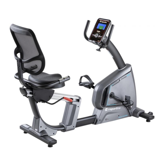
PRODUCT DESCRIPTION 1. Console 2. Middle post 3. Front stabilizer 4. Pedal 5. Rear stabilizer 6. Backrest 7. Seat 8. Pedal 9. Handlebars TECHNICAL SPECIFICATIONS Unfolded dimension 1545 x 650 x 1140 mm Maximal load capacity 120 kg Speed ratio 10.3 Load Wheel 280/9 kg... -
Page 6: Assembly
ASSEMBLY PREPARATION Name Specification M6×35 Allen screw M8×50×20 Allen screw M12×60 Allen screw... - Page 7 M10×70×20 Allen screw M4×16 Screw ST4×12 Screw Φ8 Flat washer Φ10 Spring washer Allen screw M8x30 M6×15 Allen screw Hexagon socket head large flat head full tooth bolt M8x10 M6×40 Flat washer 5×80×80S Allen key 6×66×144 Allen key t4.0×38×145 Wrench Prepare all parts and tools in clean and free space.
- Page 9 STEP 1 Attach the front stabilizer (2) to the main frame (1) using a spring washer (36), flat washer (96) and screw (26). STEP 2 Attach the rear stabilizer (3) to the main frame (1) using a spring washer (36), flat washer (96) and bolt (26).
- Page 10 STEP 3 Connect the motor communication cable (82) to the middle post cable (83). Attach the middle post (4) to the main frame (1) with the screw (25). STEP 4 Connect the console cable (83) to the pulse cable (86). Attach the console (81) to the middle post (4) with the screw (32).
- Page 11 STEP 5 Attach the handle covers L (54) and handle covers R (55) to the middle post with screws (29). STEP 6 Attach the handles with the hand knob (65). Move the handles to a suitable position. Attach the front grip cover (56) with the screw (31).
- Page 12 STEP 7 Attach the left pedal (63) and the right pedal (64) to the main frame (1). STEP 8 Attach the brake adjustment lever (8) to the seat with the screw (94). Attach the backrest to the backrest holder with the screw (93).
- Page 13 STEP 9 Attach the seat (60) to the saddle holder with the screw (23) STEP 10 Attach the pulse sensor handles (6) to the seat with the screw (24), nut (42), and flat washer (34). Connect the pulse cables (87 and 88).
- Page 14 STEP 11 Attach the backrest (61) to the backrest bracket (11) with the screw (57). STEP 12 Plug in power.
-
Page 15: Console
CONSOLE Buttons Increase load / navigation key Down Decrease load / navigation button Mode / Enter Confirm settings or selections Reset Holding the button for 2 seconds resets the setting / entering the setting / returning to the main menu in the setting or pausing mode Start / Stop Starts or stops the device Recovery... -
Page 16: Use
Turn on Connect the device to the socket, the console will start, and all the data will be displayed for 2 seconds (Fig. 1). Fig. 1 Program selection Use the UP and DOWN buttons to select the manual program (Fig. 2) - beginner (Fig. 3) - advanced (Fig. - Page 17 Fig. 8 Manual program Press "Start" on the home page to enter the manual mode and start the program. Use the "Up" and "Down" buttons to select the manual mode and confirm with "Mode / Enter". Use the "Up" and "Down" buttons to set the time (Fig. 9), distance (Fig. 10), calories (Fig. 11), heart rate (Fig.
- Page 18 Beginner Use the "Up" and "Down" buttons to select the beginner and confirm with "Mode / Enter". Use the "Up" and "Down" buttons to select mode 1 - 4 (Fig. 14) and confirm with "Mode / Enter". Use the "Up" and "Down" buttons to set the time. Press "Start / stop"...
- Page 19 Fig. 16 Cardio Use the "Up" and "Down" buttons to select H.R.C and confirm with "Mode / Enter". Use the "Up" and "Down" buttons to set the age (Fig. 17). Use the "Up" and "Down" buttons to select 55% (Fig. 18), 75%, 90% or TAG (user setting, original value: 100).
- Page 20 Use the "Up" and "Down" buttons to set the profile (Fig. 20). The user must set 20 parts, in each of which he must set the resistance. During the setting, the user can exit the setting by pressing the "Mode / Enter" button for 2 seconds. Use the "Up"...
-
Page 21: Advantages Of Recumbtion
Fig. 25 Fig. 26 ERROR MESSAGES E-1: heart rate not detected E-4: % of body fat and BMI is below 5 or above 50 (Fig. 27) Fig. 27 NOTE: The device switches to standby mode if it is not used for 4 minutes. Press any button to wake up the device. -
Page 22: Maintenance
Touching your toes Slowly bend your back from hips. Keep your back and arms relaxed while stretching downwards to your toes. Do it as far as you are able and hold the position for 15 seconds. Bend your knees slightly. Upper thigh Lean against a wall with one hand. -
Page 23: Environment Protection
• The heart rate monitor is not a medical device. It provides only approximate information about your average heart rate, and any suggested pulse rate is not medically binding. Accumulated data may not always be accurate regarding uncontrollable human and environmental factors. ENVIRONMENT PROTECTION After the product lifespan expired or if the possible repairing is uneconomic, dispose it according to the local laws and environmentally friendly in the nearest scrapyard. -
Page 24: Diagram
DIAGRAM... -
Page 25: Parts List
PARTS LIST Name Qty. Name Qty. Spring washer Φ10 Main frame Circlip for shaft Φ8 Front stabilizer Circlip for shaft Φ10 Rear stabilizer Circlip for shaft Φ12 Middle post Circlip for shaft Φ17 Handlebars Allen screw M6×20 Handlebars with pulse sensor Seat post Nut M8 Brake adjustment round bar... -
Page 26: Terms And Conditions Of Warranty, Warranty Claims
Power communication wire 750 Pulley Adjuster Square pipe plug Power adapter Square pipe plug Spring wire 2000 mm Wire plug Pulse cable 1, 2x 100 mm Hole plug Pulse cable 2, 650 mm Eccentric shaft Handle pulse Foam grip Magnet Brake line Motor belt Rubber stop... - Page 27 • Improper maintenance • Mechanical damages • Regular use (e.g. wearing out of rubber and plastic parts, moving mechanisms, joints, wear of brake pads/blocks, chain, tires, cassette/multi wheel etc.) • Unavoidable event, natural disaster • Adjustments made by unqualified person •...
- Page 28 26847264 VAT ID: CZ26847264 Phone: +420 556 300 970 E-mail: eshop@insportline.cz reklamace@insportline.cz servis@insportline.cz Web: www.inSPORTline.cz inSPORTline s.r.o. Headquaters, warranty & service center: Električná 6471, Trenčín 911 01, SK CRN: 36311723 VAT ID: SK2020177082 Phone: +421(0)326 526 701 E-mail: objednavky@insportline.cz reklamacie@insportline.cz servis@insportline.cz...
Need help?
Do you have a question about the 20214 and is the answer not in the manual?
Questions and answers