Table of Contents
Advertisement
Quick Links
Advertisement
Table of Contents

Subscribe to Our Youtube Channel
Related Manuals for Resol BASIC controller


Summary of Contents for Resol BASIC controller
- Page 1 BASIC controller Solar controller Manual for the specialised craftsman Installation Operation Functions and options Troubleshooting Thank you for buying this product. Manual Please read this manual carefully to get the best performance from this unit. Please keep this manual safe.
- Page 2 Safety advice Target group Please pay attention to the following safety advice in order to avoid danger and These instructions are exclusively addressed to authorised skilled personnel. damage to people and property. Only qualified electricians should carry out electrical works. Initial installation must be effected by the system owner or qualified personnel Instructions named by the system owner.
-
Page 3: Table Of Contents
BASIC controller With its versatile software, the BASIC controller can control even complex systems wheel ® , offers many possibilities to signal different system states. 2 microbuttons for easily and reliably. 3 pre-configured system layouts facilitate the commissioning. The quick access to the manual mode and the holiday function are located underneath operation via 2 main buttons and 1 adjustment dial, the Lightwheel ®... -
Page 4: Overview
Overview • 2 relay outputs (incl. 1 potential-free extra-low voltage relay) Technical data • 4 inputs for Pt1000, Pt500 or KTY temperature sensors Inputs: 4 inputs for Pt1000, Pt500 or KTY temperature sensors, 1 V40 impulse input • 1 V40 impulse input Outputs: 1 semiconductor relay, 1 potential-free extra-low voltage relay, 1 PWM •... -
Page 5: Installation
Installation 2.2 Electrical connection 2.1 Montage ATTENTION! ESD damage! Electrostatic discharge can lead to damage to electronic com- WARNING! Electric shock! ponents! Upon opening the housing, live parts are exposed! Take care to discharge properly before touching the Always disconnect the device from power supply inside of the device! To do so, touch a grounded sur- before opening the housing! face such as a radiator or tap! -
Page 6: System Overview
Furthermore, the controller can be connected to a PC or integrated into a net- ® ® work via the VBus /USB or VBus /LAN interface adapter (not included). Different solutions for visualisation and remote parameterisation are availabe on the website www.resol.com. Note More accessories on page 40. -
Page 7: Systems
2.5 Systems System 1: Standard solar system with 1 store Sensors Relay Temperature 1 / GND Solar pump R1 / N / PE collector Free R2 / R2 Sensors Relais Temperature store 2 / GND base VBus Free 3 / GND Free 4 / GND Free... - Page 8 System 2: Solar system with 1 store and afterheating Sensors Relay Temperature collector 1 / GND Solar pump R1 / N / PE Sensors Relais Temperature store 2 / GND Afterheating R2 / R2 base Temperature 3 / GND afterheating Free 4 / GND Free...
- Page 9 System 3: Standard solar system with 1 store Sensors Relay Temperature 1 / GND Solar pump R1 / N / PE collector Valve washing machine R2 / R2 Sensors Relais Temperature store 2 / GND base VBus Free 3 / GND Temperature washing 4 / GND machine inlet...
-
Page 10: Operation And Function
Operation and function Electrical connection of a high-effi ciency pump ( HE pump) 3.1 Buttons and adjustment dial Speed control of a HE pump is possible via a PWM signal / 0-10 V control. The pump has to be connected to the relay (power supply) as well as to one of the PWM A/B outputs of the controller. -
Page 11: Control Lamp
3.3 Control lamp The controller is equipped with a multicolour LED in the centre of the Lightwheel ® The status level consists of different display channels which indicate display values indicating the following states: and messages. The menu level consists of the balance value menu and several menu items each of Colour Permanently shown Flashing... -
Page 12: Resetting Balance Values
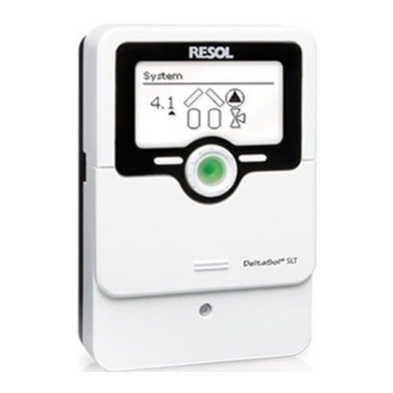
Selecting and adjusting options / functions System- Monitoring-Display An option or function containing adjustment values are marked with PUSH. System-Monitoring- Display In order to access the sub-menu of the option, select the option by turning the Lightwheel ® and press the right button ( In order to activate an option, select ON. - Page 13 4.1 System screen The system selected is indicated in the System-Monitoring-Display. It consists of several system component symbols which are – depending on the current status of the system – either flashing, permanently shown or hidden. Sensor Sensor Collectors with collector sensor Store 1 and 2 with heat exchanger Collector 1...
-
Page 14: Further Indications
4.2 Further indications Status level / Measurement values Smiley During normal operation of the controller, the display is in the status menu indicat- If the controller operates faultlessly (normal operation), a smiley is displayed. ing the values shown in the table (depending on the system selected). In addition to the display values, possible error messages are indicated in the status Fault indication menu (see page 36). -
Page 15: Balance Values
Balance values Commissioning The balance value menu indicates the balance values. When the hydraulic system is filled and ready for operation, connect the controller to the mains. Display Description The controller runs an initialisation phase in which all symbols are indicated in the h R1 Operating hours relay 1 display. - Page 16 Commissioning 1. Time: Complete the commissioning menu by pressing the right button ( Adjust the clock time. First of all adjust the hours, then the minutes. The controller is then ready for operation and nor- mally the factory settings will give close to optimum operation.
-
Page 17: Indications, Functions And Options
An additional document including a list with all options and parameters can be downloaded at www.resol.com. FLLT Filling time active 8.1 Status level Indicates the time adjusted in tFLL, running backwards. - Page 18 Display of store temperatures Display of other temperatures TSTB, etc. TWAMA, etc. Other measured temperatures Store temperatures Display range: -40 … +260 °C Display range: -40 … +260 °C Indicates the current temperature at the washing machine inlet. The display of Displays the current store temperature.
- Page 19 Display of heat quantity kW /MW Heat quantity in kWh / MWh Indicates the heat quantity produced in the system. For this purpose, the heat quantity measurement option has to be enabled. The fl ow rate as well as the values of the reference sensors fl...
-
Page 20: Menu Overview
8.2 Menu overview BALAN WAMA DATE » 21 » 26 » 30 » 33 BALANCE VALUES DATE MANUAL MODE COOL BLPR LANG » 22 » 27 » 30 » 33 SYSTEM SELECTION COOLING BLOCKING LANGUAGE FUNCTIONS PROTECTION OHQM LOAD » 27 »... - Page 21 Balance values 1 Operating hours counter BALAN hR 1 (… 2) Oper. hours PUSH Relay 1 … 2 WAMA Washing machine R (1, 2) cycles Operating hours counter DAYS The operating hours counter accumulates the operating hours of the relay Operating days (h R1 / h R2).
- Page 22 Adjustment level 2 System Selecting the system Each system has pre-programmed options and adjustments which can be activated Basic system PUSH Adjustment range: 1 … 3 or changed respectively if necessary. Select the system first (see page 10). Factory setting: 1 BACK PUSH T control...
- Page 23 4 Collector emergency shutdown When the collector temperature exceeds the adjusted collector emergency tem- perature, the solar pump (R1 / R2) switches off in order to protect the system Collector emergency temperature components against overheating (collector emergency shutdown). If the maximum PUSH Adjustment range: 80 …...
- Page 24 Tube collector function This function is used for improving the switch-on behaviour in systems with OTCO OTCO (2) non-ideal sensor positions (e. g. with some tube collectors). Tube collector function This function operates within an adjusted time frame. It activates the collector Selection: ON / OFF PUSH Factory setting: OFF...
- Page 25 5 Drainback option In a drainback system the heat transfer fluid will flow into a holding tank if solar loading does not take place. The drainback option initiates the filling process if solar Drainback option loading is about to start. If the drainback option is activated, the following adjust- Selection: OFF / ON PUSH Factory setting: OFF...
- Page 26 Note If the drainback function ODB is activated, the factory settings of the pa- rameters DT O, DT F und DT S will be adapted to values suiting drainback systems: DT O = 10 K DT F = 4 K DT S = 15 K Additionally, the adjustment range and the factory setting of the collector emergency shutdown CEM will change:...
- Page 27 7 Cooling function Note COOL OSTC If the temperature at the store sensor reaches 95 °C, the cooling function Store cooling option PUSH will be blocked. The switch-on hysteresis is -5 K. Adjustment range: OFF / ON Factory setting: OFF Note If the cooling function is activated, the drainback option will not be avail- DTCO...
- Page 28 9 Relay control With this parameter, the relay control type can be adjusted. The following types can be selected: REL / Relay control Adjustment for standard pump without speed control Selection: ONOF, Puls, PUSH PSOL, PHEA, 0 - 10, ADAP •...
- Page 29 10 Holiday function The holiday function is used for operating the system when no water consumption H-DAY OCCO is expected, e. g. during a holiday absence. This function cools down the system in Collector cooling option PUSH order to reduce the thermal load. Adjustment range: OFF / ON Factory setting: OFF Only if the holiday function has been activated with the parameter DAYS will the...
- Page 30 Note When the drainback option is activated, the holiday function will not be available and cannot be selected by means of the microbutton Note If the holiday function is activated, the drainback option will not be avail- able. 11 Manual mode For control and service work, the operating mode of the relays can be manually MAN1 adjusted.
- Page 31 13 Heat quantity measurement The heat quantity measurement can be carried out in 3 different ways: without V40 OHQM OHQM flowmeter, with V40 flowmeter or with Grundfos Direct Sensor Heat quantity measurement option PUSH Adjustment range: OFF / ON Flow sensor Factory setting: OFF FTYPE Heat quantity measurement type...
- Page 32 13 Heat quantity measurement with V40 flowmeter: The heat quantity measurement uses the difference between the flow temperature Tcold measured at S3 and the adjusted return temperature Tcold and the flow rate Cold water temperature transmitted by the flowmeter. Adjustment range: 0 … 20 °C Adjust 2 in the channel FTYPE Factory setting: 10 °C Note...
- Page 33 15 Time and date TIME / Time The controller is equipped with a real time clock required e. g. for the thermostat DATE Adjustment range: 00:00 … 23:59 function. Factory setting: 12:00 In the display, the lower line indicates the day followed by the month. PUSH ADST Automatic daylight savings time...
- Page 34 17 Function control T monitoring T HI T too high option This function is used for monitoring the temperature difference.. The message T PUSH Selection: ON / OFF too high is shown, if solar loading has been carried out for a period of 20 min with a Factory setting: ON differential higher than 50 K.
- Page 35 17 Maximum store temperature STMAX This function is used for detecting and indicating if the adjusted maximum store temperature has been exceeded. The controller compares the current store tem- PUSH perature to the adjusted maximum store temperature, thus monitoring the store loading circuits.
-
Page 36: Messages
Messages In the case of an error, the control LED starts flashing red and a message is indicated In the case of a sensor error, the system switches off, and a message appears on the in the status display. A warning triangle is additionally indicated. If more than one display. -
Page 37: Troubleshooting
10 Troubleshooting If a malfunction occurs, a message will appear on the display of the controller. ® Control LED in the Lightwheel is flashing red. The symbol is indicated on the display and the symbol flashes. Lightwheel ® or display are permanently off. Sensor fault. - Page 38 Pump is overheated, but no heat transfer from the collector to the store, flow Pump starts up very late. and return have the same temperature; perhaps also bubbling in the lines. Air or gas bubbles in the system? Switch-on temperature difference Vent the system;...
- Page 39 The solar circuit pump does not work, although the collector is considerably Insulation close enough to the store? warmer than the store. Replace insulation or increase it. LED in Lightwheel ® illuminated? If not, press the right button. Display Are the store connections insulated? illuminated again? There is no current;...
-
Page 40: Accessories
Accessories Sensors SD3 Smart Display / GA3 Large Display Overvoltage protection AM1 Alarm module device V40 fl owmeter DL2 Datalogger DL3 Datalogger ® ® VBus / USB & VBus / LAN interface adapters... -
Page 41: Sensors And Measuring Instruments
11.1 Sensors and measuring instruments Sensors AM1 Alarm module The product range includes high-precision platinum temperature sensors, flatscrew The AM1 Alarm Module is designed to signal system failures. It is to be connected sensors, outdoor temperature sensors, indoor temperature sensors, cylindrical clip- ®... -
Page 42: Index
12 Index Accessories............................40, 41 Night circulation ............................27 Afterheating function ..........................5 Operating days ............................21 Balance values ............................. 15, 21 Blocking protection ..........................30 Priority logic .............................. 29 Collector cooling ............................. 23 Resetting balance values ......................... 12 Collector emergency shutdown ......................23 Return preheating ............................ - Page 44 HR Solar Distributed by: Leehove 4 2678 MC De Lier Niederlande tel 0031 0174-523303 fax 0031 0174384687 info@hrsolar.nl www.hrsolar.nl © All contents of this document are protected by copyright.
Need help?
Do you have a question about the BASIC controller and is the answer not in the manual?
Questions and answers