Table of Contents

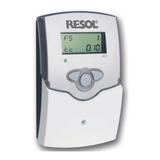
Summary of Contents for Resol EC1
- Page 1 Variable controller for circulation systems Thank you for buying this RESOL product. Manual Please read this manual carefully to get the best performance from this unit. Please keep this manual carefully. www.resol.com...
- Page 2 Safety advice Target group Please pay attention to the following safety advice in order to avoid danger and These instructions are exclusively addressed to authorised skilled personnel. damage to people and property. Only qualified electricians should carry out electrical works. Initial installation must be effected by the system owner or qualified personnel named by the system owner.
-
Page 3: Table Of Contents
Contents General function description ............4 Installation ................... 5 2.1 Mounting ........................5 2.2 Electrical connection ....................5 Flow switch ................... 6 Operation and function ..............6 4.1 Push buttons ........................6 4.2 Contoller parameter and indication channels ............7 4.3 Phase (Ph)........................7 4.4 Runtime / Disinfection (Rc) ..................8 4.5 Waiting time (Wc) .......................8 4.6 Switch-on delay (Dc) ....................8 4.7 Manual / Automatic mode (MM) ................8... -
Page 4: General Function Description
Overview General function description • variable controller for circulation systems • demand-oriented pump control 115 V~ Strömungsschalter 50-60 Hz • easy-to-install housing Made in Germany IP 20 • user-friendly operation 2 (1) A 115 V~ N R1 N L • intuitive menu operation via push buttons 12 13 14 18 19 20 The purpose of a circulation system is to provide the user with hot water as quick... -
Page 5: Installation
Installation Mounting Electrical connection display 115 V~ Strömungsschalter 50-60 Hz fuse Made in Germany IP 20 2 (1) A 115 V~ N R1 N L push button cover 12 13 14 18 19 20 load terminals sensor terminal S1 for 17/18 circulating pump mains terminals cable conduits... -
Page 6: Flow Switch
Flow switch Operation and function The flow switch detects water flow in your pipe system and indicates if water is Push buttons being drawn-off. Along with other variables, the controller analyses these data and controls the circulating pump. As the flow switch detects water movement in one direction only, please pay attention to the correct flow direction when mounting the device. -
Page 7: Contoller Parameter And Indication Channels
Contoller parameter and indication channels Phase (Ph) • Ph = Phase Phase 1: The contactor has been switched on, the circulating pump is put into operation for the runtime Rc (Runtime of circulation). Phase 2: Water has been tapped over a longer period, the circulating pump switches off after the runtiume Rc is over. -
Page 8: Runtime / Disinfection (Rc)
Runtime / Disinfection (Rc) Switch-on delay (Dc) Rc: Circulation runtime Dc: Delay (Runtime of circulation) Factory setting: 0 s Factory setting: 2 Min Adjustment range: 0 … 2 s Indication in minutes The switch-on delay is the time during which the flow switch FS08 must be closed Adjustment range: 0:01 …... -
Page 9: Check Value Flow Switch (Fs)
Wc depending on the current phase. During phase c1, the value tc indicates the counter from 0 to Rc, in phase c2, the counter from 0 to Wc. If the EC1 controller does not work correctly, please check the following items: 4.10... - Page 12 - they only represent use outside the copyright requires the approval of RESOL – Elektronische some examples. They can only be used at your own risk. No liability is assumed for Regelungen GmbH.


Need help?
Do you have a question about the EC1 and is the answer not in the manual?
Questions and answers