
Subscribe to Our Youtube Channel
Related Manuals for Pepperl+Fuchs VAA-4E4A-G20-ZEJ/M2L-P7-GEB


Summary of Contents for Pepperl+Fuchs VAA-4E4A-G20-ZEJ/M2L-P7-GEB
- Page 1 FACTORY AUTOMATION MANUAL VAA-4E4A-G20-ZEJ/M2L-P7-GEB AS-Interface Motor Control Module...
- Page 2 VAA-4E4A-G20-ZEJ/M2L-P7-GEB With regard to the supply of products, the current issue of the following document is ap- plicable: The General Terms of Delivery for Products and Services of the Electrical Indus- try, published by the Central Association of the Electrical Industry (Zentralverband Elektrotechnik und Elektroindustrie (ZVEI) e.V.) in its most recent version as well as the...
-
Page 3: Table Of Contents
VAA-4E4A-G20-ZEJ/M2L-P7-GEB Introduction................. 4 Content of this Document ..............4 Target Group, Personnel..............4 Symbols Used ..................4 Product Description ..............6 Use and Application................6 Housing....................7 Displays and Operating Elements ............7 Interfaces and Connections..............9 Installation................. 11 Storage and Transport ............... 11 Unpacking................... -
Page 4: Introduction
VAA-4E4A-G20-ZEJ/M2L-P7-GEB Introduction Introduction Content of this Document This document contains information required to use the product in the relevant phases of the product life cycle. This may include information on the following: Product identification Delivery, transport, and storage Mounting and installation... -
Page 5: Symbols Used
VAA-4E4A-G20-ZEJ/M2L-P7-GEB Introduction Symbols Used This document contains symbols for the identification of warning messages and of informative messages. Warning Messages You will find warning messages, whenever dangers may arise from your actions. It is mandatory that you observe these warning messages for your personal safety and in order to avoid property damage. -
Page 6: Product Description
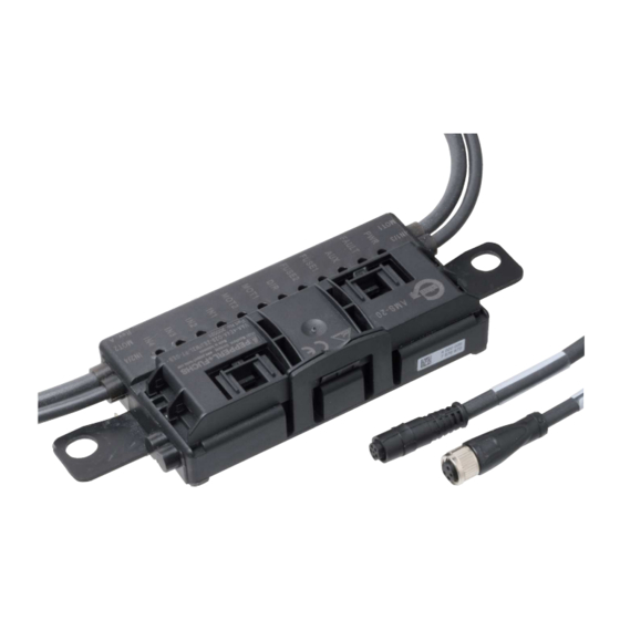
Product Description Use and Application The VAA-4E4A-G20-ZEJ/M2L-P7-GEB motor control module is an AS-Interface connection module for controlling 1 or 2 DC roller motors. The module is optimized for ITOH Denki PM...XE/XP motors, but can also be used for compatible DC motors. -
Page 7: Housing
VAA-4E4A-G20-ZEJ/M2L-P7-GEB Product Description Housing The housing is made entirely of plastic, with the exception of the hinge pins for the hinged cable guide. The main components are: A mounting base with electronics coated in hot-melt adhesive A folding guide cage as a cable guide for the AS-Interface flat cable. - Page 8 VAA-4E4A-G20-ZEJ/M2L-P7-GEB Product Description PWR LED, Green FAULT LED, Red Status Flashing Flashing Peripheral fault, collective error message for: AUX external auxiliary power is missing or is inverted Overload of the sensor supply (IN+, IN-) Overload of the speed signal SPEED AS-Interface voltage missing The AUX LED shows the status of the AUX external auxiliary voltage supply.
-
Page 9: Interfaces And Connections
VAA-4E4A-G20-ZEJ/M2L-P7-GEB Product Description Motor Direction of Rotation Indicator LED DIR Yellow Status Direction of rotation to the right (ITOH Denki) Direction of rotation to the left (ITOH Denki) Status Indicators for Sensors IN1, IN2, IN3, IN4 The LED IN1 for input 1, LED IN2 for input 2, LED IN3 for input 3, and LED IN4 for input 4 indicate the switch states of the inputs. - Page 10 VAA-4E4A-G20-ZEJ/M2L-P7-GEB Product Description Motor Supply from Auxiliary Power The motors are supplied with power directly from the AUX external auxiliary power and this cannot be switched. The voltage is always present at contacts 1 and 3 of the 5-pin M8 connector.
-
Page 11: Installation
Retain the original packaging in case the device must be stored or shipped again at a later date. Should you have any questions, please contact Pepperl+Fuchs. Connecting the AS-Interface and Auxiliary Power Flat Cable The motor control module is connected to the AS-Interface network and the AUX auxiliary power via the AS-Interface flat cable. - Page 12 VAA-4E4A-G20-ZEJ/M2L-P7-GEB Installation YELLOW BLACK Figure 3.1 Connecting Flat Cables on the Narrow Side Connecting Flat Cables on the Wide Side The profile edge is not visible from above. For orientation purposes in the figure below, the edge is shown as a hidden edge drawn with a dotted line.
- Page 13 VAA-4E4A-G20-ZEJ/M2L-P7-GEB Installation YELLOW BLACK Figure 3.2 Connecting flat cables on the wide side (profile edge as dotted line) Flat Cable Inserted Incorrectly The figure below shows an incorrectly inserted flat cable. The profile edge (2) does not point to the motor control module; the flat cable is therefore inserted with reverse polarity. The flat cable is located on the reverse polarity protection (1) with a curvature, which means that the cable guide cannot be closed completely (mechanical reverse polarity protection).
-
Page 14: Connecting Motors And Sensors
VAA-4E4A-G20-ZEJ/M2L-P7-GEB Installation Connecting Motors and Sensors IN1/3 IN2/4 AS-Interface + AS-Interface - MOT1 & MOT2 FUSE MOT+ FAULT SPEED MOT- AUX+ AUX- Figure 3.4 Connection wiring diagram for motors and sensors... -
Page 15: Commissioning
VAA-4E4A-G20-ZEJ/M2L-P7-GEB Commissioning Commissioning AS-Interface Communication Assigning the AS-Interface Data Bits 4 data bits are available for communication between the motor control module and the master and 4 data bits are available for controlling the motors. The following designations apply below: DI0...DI3 for AS-Interface input data (motor control module to master) - Page 16 VAA-4E4A-G20-ZEJ/M2L-P7-GEB Commissioning Switching the Motor Direction of Rotation (DO2) You can switch the direction of rotation of the motors using the DIR control signal. The direction of rotation signal applies to both motors. To control the direction of location, you must parameterize data bit DO2 accordingly.
-
Page 17: Configuring The Start/Stop Ramps
VAA-4E4A-G20-ZEJ/M2L-P7-GEB Commissioning Speed signal U DO0 (MOT1) or DO1 (MOT2) Fast (D3=0) Slow (D3=1) 8.7 V 3.7 V 9.7 V 4.7 V Default setting Reversing the Direction of Rotation of MOT2 (P3) You can reverse the direction of rotation of MOT2 via parameter bit P3. - Page 18 VAA-4E4A-G20-ZEJ/M2L-P7-GEB Commissioning Predefined Start/Stop Ramps Ramp no. Ramp duration no ramp 50 ms 100 ms 200 ms 300 ms 500 ms (default setting) 1000 ms 1500 ms The ramp is not effective if the direction of rotation signal is switched when the motor is active.
- Page 19 VAA-4E4A-G20-ZEJ/M2L-P7-GEB Commissioning Note! Sequence for Command Transmission For each step, you generally send the data value via DO0 ... D03 first, and then the parameter value P0 ... P3. The following table depicts the contexts of the communication between the master and the motor control module.
-
Page 20: Troubleshooting
VAA-4E4A-G20-ZEJ/M2L-P7-GEB Troubleshooting Troubleshooting Fault Information and Remedy Error LED indicator Possible cause Remedy No data PWR off AS-Interface voltage is missing or is Check AS-Interface wiring communication inverted with AS-Interface PWR flashes and Module address is 0 Program module address... - Page 21 Twinsburg, Ohio 44087 · USA Tel. +1 330 4253555 E-mail: sales@us.pepperl-fuchs.com Asia Pacific Headquarters Pepperl+Fuchs Pte Ltd. Company Registration No. 199003130E Singapore 139942 Tel. +65 67799091 E-mail: sales@sg.pepperl-fuchs.com www.pepperl-fuchs.com Subject to modifications / DOCT-6161 Copyright PEPPERL+FUCHS • Printed in Germany 09/2018...
Need help?
Do you have a question about the VAA-4E4A-G20-ZEJ/M2L-P7-GEB and is the answer not in the manual?
Questions and answers