
Subscribe to Our Youtube Channel
Related Manuals for Pepperl+Fuchs VBA-4E4A-G20-ZEJ/M3L-P10


Summary of Contents for Pepperl+Fuchs VBA-4E4A-G20-ZEJ/M3L-P10
- Page 1 FACTORY AUTOMATION MANUAL VBA-4E4A-G20- ZEJ/M3L-P10 AS-Interface motor control module...
- Page 2 VBA-4E4A-G20-ZEJ/M3L-P10 With regard to the supply of products, the current issue of the following document is ap- plicable: The General Terms of Delivery for Products and Services of the Electrical Indus- try, published by the Central Association of the Electrical Industry (Zentralverband Elektrotechnik und Elektroindustrie (ZVEI) e.V.) in its most recent version as well as the...
-
Page 3: Table Of Contents
VBA-4E4A-G20-ZEJ/M3L-P10 Introduction................. 4 Content of this Document ..............4 Target Group, Personnel..............4 Symbols Used ..................4 Intended use..................5 General Safety Information..............5 Declaration of conformity..............6 Certificates and approvals............7 UL Information..................7 Product Description ..............8 Use and application ................8 Housing.................... -
Page 4: Introduction
VBA-4E4A-G20-ZEJ/M3L-P10 Introduction Introduction Content of this Document This document contains information required to use the product in the relevant phases of the product life cycle. This may include information on the following: Product identification Delivery, transport, and storage Mounting and installation... -
Page 5: Intended Use
User modification and or repair are dangerous and will void the warranty and exclude the manufacturer from any liability. If serious faults occur, stop using the device. Secure the device against inadvertent operation. In the event of repairs, return the device to your local Pepperl+Fuchs representative or sales office. Note Disposal Electronic waste is hazardous waste. -
Page 6: Declaration Of Conformity
This product was developed and manufactured under observance of the applicable European standards and guidelines. Note A Declaration of Conformity can be requested from the manufacturer. The product manufacturer, Pepperl+Fuchs GmbH, D-68307 Mannheim, has a certified quality assurance system that conforms to ISO 9001. ISO9001... -
Page 7: Certificates And Approvals
VBA-4E4A-G20-ZEJ/M3L-P10 Certificates and approvals Certificates and approvals UL Information Technical Data and Environmental Conditions This device is for indoor use only. This device may be operated in altitudes up to 2000 m. The ambient temperature range is from -25 °C to +70 °C. -
Page 8: Product Description
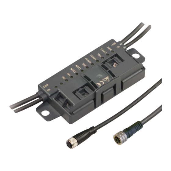
Product Description Use and application The VBA-4E4A-G20-ZEJ/M3L-P10 motor control module is an AS-Interface connection module for controlling 1 or 2 DC roller motors. The module is optimized for ITOH Denki PM ... XE/XP motors, but can also be used for compatible DC motors. -
Page 9: Housing
VBA-4E4A-G20-ZEJ/M3L-P10 Product Description Housing The housing is made entirely of plastic, except for the hinge pins for the hinged cable guide. The housing consists of following main components: a mounting base with embedded electronics a folding guide cage as a cable guide for the AS-Interface flat cable 131.5... - Page 10 VBA-4E4A-G20-ZEJ/M3L-P10 Product Description LED PWR LED FAULT Green Status Flashing Flashing Peripheral fault, collective error message for: AUX external auxiliary power is missing or is inverted Overload of the sensor supply (IN+, IN-) Overload of the speed signal SPEED AS-Interface voltage missing The AUX LED shows the status of the AUX external auxiliary voltage supply.
-
Page 11: Interfaces And Connections
VBA-4E4A-G20-ZEJ/M3L-P10 Product Description Motor direction of rotation indicator LED DIR Yellow Status Direction of rotation to the right (in accordance with ITOH Denki) Direction of rotation to the left (in accordance with ITOH Denki Table 3.3 Status indicators for IN1, IN2 sensors The IN1 LED for input 1 and IN2 LED for input 2 show the switch states of the inputs. -
Page 12: Accessories
VBA-4E4A-G20-ZEJ/M3L-P10 Product Description Motor supply from auxiliary current The motors are supplied with power directly from the AUX external auxiliary current and this cannot be switched. The voltage is always on contacts 1 and 3 of the 5-pin M8 connector. -
Page 13: Installation
Retain the original packaging in case the device must be stored or shipped again at a later date. Should you have any questions, please contact Pepperl+Fuchs. Connecting the AS-Interface and Auxiliary Power Flat Cable The motor control module is connected to the AS-Interface network and the AUX auxiliary power via the AS-Interface flat cable. - Page 14 VBA-4E4A-G20-ZEJ/M3L-P10 Installation YELLOW BLACK Figure 4.1 Connecting Flat Cables on the Narrow Side Connecting Flat Cables on the Wide Side The profile edge is not visible from above. For orientation purposes in the figure below, the edge is shown as a hidden edge drawn with a dotted line.
- Page 15 VBA-4E4A-G20-ZEJ/M3L-P10 Installation YELLOW BLACK Figure 4.2 Connecting flat cables on the wide side (profile edge as dotted line) Flat Cable Inserted Incorrectly The figure below shows an incorrectly inserted flat cable. The profile edge (2) does not point to the motor control module; the flat cable is therefore inserted with reverse polarity. The flat cable is located on the reverse polarity protection (1) with a curvature, which means that the cable guide cannot be closed completely (mechanical reverse polarity protection).
-
Page 16: Connecting Motors And Sensors
VBA-4E4A-G20-ZEJ/M3L-P10 Installation Connecting motors and sensors IN1 & IN2 AS-Interface + AS-Interface - (n.c.) MOT1 & MOT2 FUSE MOT+ FAULT SPEED MOT- AUX+ AUX- Figure 4.4 Connection wiring diagram for motors and sensors... -
Page 17: Commissioning
VBA-4E4A-G20-ZEJ/M3L-P10 Commissioning Commissioning AS-Interface slaves are usually addressed with a handheld. Connect the adapter cable VAZ- PK/G20-1M-V1-G to the handheld VBP-HH1-V3.0. AS-Interface communication Assignment of the AS-Interface data bits 4 data bits are available for communication to take place between the motor control module and the master. - Page 18 VBA-4E4A-G20-ZEJ/M3L-P10 Commissioning Switching the motor direction of rotation (DO2) You can switch the direction of rotation of the motors using the DIR control signal. The direction of rotation signal applies to both motors. To control the direction of rotation, you must parameterize data bit DO2 accordingly.
-
Page 19: Configuring The Start/Stop Ramps
VBA-4E4A-G20-ZEJ/M3L-P10 Commissioning Parameter bits P0, P1 Speed signal U Parameter bit DO0 (MOT1) or DO1 (MOT2) Fast (D3 = 0) Slow (D3 = 1) < 1 V < 1 V 4.7 V 0.7 V 5.7 V 1.7 V 7.7 V 2.7 V... - Page 20 VBA-4E4A-G20-ZEJ/M3L-P10 Commissioning Ramp number Ramp duration 100 ms 200 ms 300 ms 500 ms 1000 ms 1500 ms Table 5.9 The ramp is not effective if the direction of rotation signal is switched when the motor is active. In this case, the direction of rotation is reversed immediately.
- Page 21 VBA-4E4A-G20-ZEJ/M3L-P10 Commissioning Note Sequence for command transmission For each step, you generally send the data value via DO0 ... D03 first and then the parameter value P0 ... P2. The following table shows the contexts of communication between the master and motor control module.
- Page 22 VBA-4E4A-G20-ZEJ/M3L-P10 Commissioning Fault scenarios Step Possible fault Motor control module reaction 1 ... 6 Incorrect data or parameter values or Motor control module remains in normal mode. steps 1 ... 6 take longer than 10 s 7 or 8 Incorrect data or parameter values...
-
Page 23: Troubleshooting
VBA-4E4A-G20-ZEJ/M3L-P10 Troubleshooting Troubleshooting Fault information and remedy LED status Error indicator Possible cause Remedy No data PWR off AS-Interface voltage is missing or is Check AS-Interface wiring communication inverted with AS-Interface PWR flashes and Module address is 0 Program module address... - Page 24 Twinsburg, Ohio 44087 · USA Tel. +1 330 4253555 E-mail: sales@us.pepperl-fuchs.com Asia Pacific Headquarters Pepperl+Fuchs Pte Ltd. Company Registration No. 199003130E Singapore 139942 Tel. +65 67799091 E-mail: sales@sg.pepperl-fuchs.com www.pepperl-fuchs.com Subject to modifications / TDOCT-6525_ENG Copyright PEPPERL+FUCHS • Printed in Germany 09/2019...
Need help?
Do you have a question about the VBA-4E4A-G20-ZEJ/M3L-P10 and is the answer not in the manual?
Questions and answers