Table of Contents
Advertisement
Quick Links
Advertisement
Table of Contents

Related Manuals for Pepperl+Fuchs VAA-2E-KE1-S


Summary of Contents for Pepperl+Fuchs VAA-2E-KE1-S
- Page 1 VAA-2E-KE1-S Original Instructions Manual...
- Page 2 Phone: +49 621 776 - 0 E-mail: info@de.pepperl-fuchs.com North American Headquarters Pepperl+Fuchs Inc. 1600 Enterprise Parkway Twinsburg, Ohio 44087 Phone: +1 330 425-3555 E-mail: sales@us.pepperl-fuchs.com Asia Headquarters Pepperl+Fuchs Pte. Ltd. P+F Building 18 Ayer Rajah Crescent Singapore 139942 Phone: +65 6779-9091 E-mail: sales@sg.pepperl-fuchs.com https://www.pepperl-fuchs.com...
-
Page 3: Table Of Contents
General safety instructions ................7 Transfer time of the safety-relevant information......... 8 Probability of Failure on Demand Calculation ..........8 Product Description ....................9 AS-Interface Safety at Work VAA-2E-KE1-S..........9 Connections and Indications................ 9 Interface Properties..................10 Commissioning......................12 Preparation....................12 Configuring the AS-Interface Safety Monitor.......... - Page 4 VAA-2E-KE1-S Contents Annex B........................21 Summary of the Requirements for Categories acc. to ISO 13849-1 ..21 Certificates ....................22...
-
Page 5: Introduction
VAA-2E-KE1-S Introduction Introduction Content of this Document This document contains information required to use the product in the relevant phases of the product life cycle. This may include information on the following: • Product identification • Delivery, transport, and storage •... -
Page 6: Symbols Used
This product was developed and manufactured in line with the applicable European standards and directives. Note A declaration of conformity can be requested from the manufacturer. The product manufacturer, Pepperl+Fuchs Group, 68307 Mannheim, Germany, has a certified quality assurance system that conforms to ISO 9001. ISO9001... -
Page 7: Safety
VAA-2E-KE1-S Safety Safety Intended Use When used as intended, the AS-Interface safety module allows the operation of sensor-con- trolled personal protective equipment up to category 4 and PL e as per ISO 13849 or up to SIL 3 as per EN/IEC 61508 and EN/IEC 62061 in combination with an appropriately programmed AS-Interface safety monitor. -
Page 8: Transfer Time Of The Safety-Relevant Information
VAA-2E-KE1-S Safety Note The plant management is responsible for heeding local safety regulations. Transfer time of the safety-relevant information The transfer time depends essentially on the monitor. The corresponding documentation and the switch-off times of the actuators must be observed. -
Page 9: Product Description
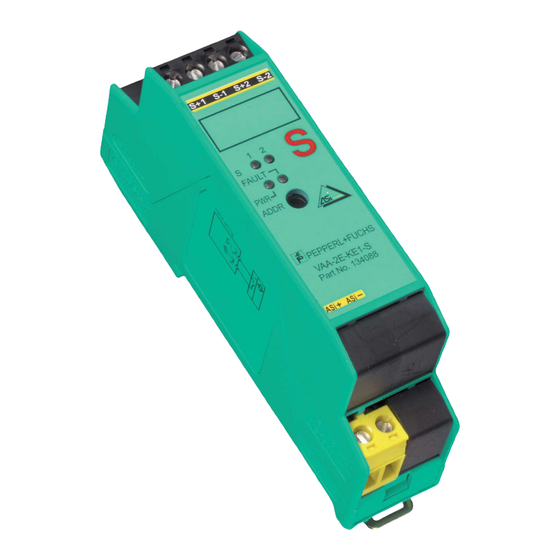
VAA-2E-KE1-S Product Description Product Description AS-Interface Safety at Work VAA-2E-KE1-S The VAA-2E-KE1 is an AS-Interface safety module with two safety-related inputs. A dual-chan- nel mechanical switch or single-channel mechanical switch can be connected to the two inputs. The housing is only 22.5 mm wide and 48.5 mm tall and takes up little space in the switch cabinet. -
Page 10: Interface Properties
VAA-2E-KE1-S Product Description Indications Designation Description FAULT Fault indication: red LED Red: communication error or address is 0 AS-Interface voltage: green LED Switching status of input channel 1: yellow LED Switching status of input channel 2: yellow LED Interface Properties AS-Interface The KE1 series module is connected to the AS-Interface via removable terminals. - Page 11 VAA-2E-KE1-S Product Description Safety Category The module contains two independent and redundant input channels that individually meet the requirements of category 4 / PL e in accordance with EN ISO 13849-1. Crossed Circuit Monitoring The inputs are monitored for inter-crossed circuits. The crossed circuit monitoring function is able to detect low-resistance crossed circuits between the two inputs caused by a metallic con- nection.
-
Page 12: Commissioning
Check the package contents against your order and the shipping documents to ensure that all items are present and correct. Should you have any questions, direct them to Pepperl+Fuchs. Retain the original packaging in case the device is to be stored or shipped again at a later date. -
Page 13: Operating Mode
VAA-2E-KE1-S Commissioning Note In the case of single-channel safety functions, test the function for each channel. For applications of category 4/PL e in accordance with ISO 13849-1 or SIL 3 in accordance with EN/IEC 61508 and EN/IEC 62061, the two inputs must be monitored using the safety monitor to ensure that they are synchronous. -
Page 14: Maintenance And Repair
VAA-2E-KE1-S Maintenance and Repair Maintenance and Repair Maintenance and repair Regular function tests may be necessary, depending on the safety category. -
Page 15: Technical Data
VAA-2E-KE1-S Technical Data Technical Data 50.5 22.5 48.5 General specifications Slave type Safety-Slave UL File Number E87056 Indicators/operating means LED FAULT error display; LED red red: communication error or address is 0 LED PWR AS-Interface voltage; LED green LED IN switching state (input);... - Page 16 VAA-2E-KE1-S Technical Data Data bits (function via AS- input output Interface) dyn. safety code 1 - dyn. safety code 1 - dyn. safety code 2 - dyn. safety code 2 - Parameter bits (program- function mable via AS-i) not used...
-
Page 17: Annex A
VAA-2E-KE1-S Annex A Annex A Application Examples Note The examples listed here correspond to our understanding of the categories in accordance with ISO 13849-1 and should not be regarded as binding. Category 2 The safety function(s) must be tested at appropriate intervals of time by the machine control system. - Page 18 VAA-2E-KE1-S Annex A Example 2: If a dangerous failure (short circuit) of the switches cannot be excluded, these switches must be duplicated and connected in series. Channel 1 Channel 2 Figure 7.3 Example 3: If a short circuit in the cabling across the switches cannot be excluded, both channels are needed to achieve a category 3 safety function.
- Page 19 VAA-2E-KE1-S Annex A Danger! The function block "Dual-channel, independent" must not be used in example 3. Category 4 The occurrence of a fault and an accumulation of faults must not lead to the loss of the safety function. Example 1: Connection of a dual-channel mechanical position switch.
- Page 20 VAA-2E-KE1-S Annex A Dual-channel, dependent Dual-channel, force-guided Danger! The function block "Dual-channel, independent" must not be used. Warning! The cable length between the module and the sensor is limited to 300 m.
- Page 21 VAA-2E-KE1-S Annex B Annex B Summary of the Requirements for Categories in Accordance with ISO 13849-1 Essential princi- Cate- ple to achieve gory Summary of the requirement System behavior safety The safety-related parts of machine If a fault occurs, it can lead...
- Page 22 VAA-2E-KE1-S Annex B Certificates Approvals in accordance with EN ISO 13849-1, EN/IEC 62061 and EN/IEC 61508.
- Page 23 VAA-2E-KE1-S Annex B...
- Page 24 Pepperl+Fuchs Quality Download our latest policy here: www.pepperl-fuchs.com/quality www.pepperl-fuchs.com © Pepperl+Fuchs · Subject to modifications Printed in Germany 182314 / DOCT-0694D...
Need help?
Do you have a question about the VAA-2E-KE1-S and is the answer not in the manual?
Questions and answers