
Related Manuals for Pepperl+Fuchs VAA-2E1A-CB10-SJ/E2J-FL


Summary of Contents for Pepperl+Fuchs VAA-2E1A-CB10-SJ/E2J-FL
- Page 1 VAA-2E1A-CB10-SJ/E2J-FL, VAA-2E2A-CB10-SJ/E2J-FL AS-Interface Safety at Work Version 2.0 Manual...
- Page 2 Phone: +49 621 776 - 0 E-mail: info@de.pepperl-fuchs.com North American Headquarters Pepperl+Fuchs Inc. 1600 Enterprise Parkway Twinsburg, Ohio 44087 Phone: +1 330 425-3555 E-mail: sales@us.pepperl-fuchs.com Asia Headquarters Pepperl+Fuchs Pte. Ltd. P+F Building 18 Ayer Rajah Crescent Singapore 139942 Phone: +65 6779-9091 E-mail: sales@sg.pepperl-fuchs.com https://www.pepperl-fuchs.com...
-
Page 3: Table Of Contents
VAA-2E1A-CB10-SJ/E2J-FL, VAA-2E2A-CB10-SJ/E2J-FL Contents Declaration of Conformity..................5 Safety .......................... 6 Symbols Used ....................6 Intended Use ....................6 General Safety Information................7 Residual Risk ....................7 Safety Monitor Requirements............... 7 Cabling Requirements................... 8 Switch or Mechanical Contact Requirements..........8 Fault Eliminations ..................8 Transmission Time for Safety-Related Information ........ - Page 4 VAA-2E1A-CB10-SJ/E2J-FL, VAA-2E2A-CB10-SJ/E2J-FL Contents Operation ........................18 Safety-Related Inputs ..................18 Conventional (Non-Safe) Electronic Outputs..........18 Servicing........................19 Troubleshooting .......................20...
-
Page 5: Declaration Of Conformity
This product was developed and manufactured in line with the applicable European standards and directives. Note A declaration of conformity can be requested from the manufacturer. The product manufacturer, Pepperl+Fuchs GmbH, 68307 Mannheim, Germany, has a certified quality assurance system that conforms to ISO 9001. ISO9001... -
Page 6: Safety
VAA-2E1A-CB10-SJ/E2J-FL, VAA-2E2A-CB10-SJ/E2J-FL Safety Safety Symbols Used Safety-Relevant Symbols Danger! This symbol indicates an imminent danger. Non-observance will result in personal injury or death. Warning! This symbol indicates a possible fault or danger. Non-observance may cause personal injury or serious property damage. -
Page 7: General Safety Information
In the event of any serious errors, stop using the device. Secure the device against unintended operation. To have the device repaired, return it to your local Pepperl+Fuchs representative or your sales center. Only qualified electrical specialists are authorized to perform maintenance work. -
Page 8: Cabling Requirements
VAA-2E1A-CB10-SJ/E2J-FL, VAA-2E2A-CB10-SJ/E2J-FL Safety The wiring and programming of the safety monitor determine whether or not the required safety function performs correctly. This also applies to the required safety response after a code fault or failure (see also safety monitor documentation). The safety function (including all safety- related sensors) must be checked prior to initial commissioning. -
Page 9: Product Description
Product Description Product Description Function The VAA-2E1A-CB10-SJ/E2J-FL is an AS-Interface safety module with two safety-related inputs and one conventional output. The VAA-2E2A-CB10-SJ/E2J-FL is an AS-Interface safety module with two safety-related inputs and two conventional outputs. A dual-channel mechani- cal switch can be connected to the two safety-related inputs on both devices, or a single-chan- nel mechanical switch can be connected to each device. -
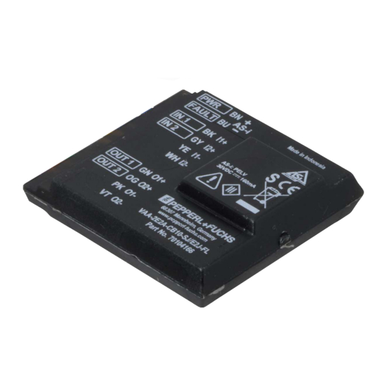
Page 10: Indicators And Operating Elements
VAA-2E1A-CB10-SJ/E2J-FL, VAA-2E2A-CB10-SJ/E2J-FL Product Description Indicators and Operating Elements AS-Interface: BN = AS-i+ BU = AS-i- FAULT BK = IN 1 GY = IN 2 YE = WH = OUT 1 OUT: GN = PK = Figure 3.2 VAA-2E1A-CB10-SJ/E2J-FL AS-Interface status indicator... -
Page 11: Connections
VAA-2E1A-CB10-SJ/E2J-FL, VAA-2E2A-CB10-SJ/E2J-FL Product Description Connections VAA-2E1A-CB10-SJ/E2J-FL Connections AS-Interface: BN = AS-i+ BU = AS-i- FAULT BK = IN 1 GY = IN 2 YE = WH = OUT 1 GN = OUT: PK = Figure 3.4 VAA-2E1A-CB10-SJ/E2J-FL Safety-Related Inputs Color... -
Page 12: Operating Principle
VAA-2E1A-CB10-SJ/E2J-FL, VAA-2E2A-CB10-SJ/E2J-FL Product Description Color Designation Description Black (BK) Mechanical switch 1 + Gray (GY) Mechanical switch 2 + Yellow (YE) Mechanical switch 1 - White (WH) Mechanical switch 2 - Conventional (Non-Safe) Electronic Output Color Designation Description Green (GN) -
Page 13: Cross Circuit Monitoring Of Inputs
VAA-2E1A-CB10-SJ/E2J-FL, VAA-2E2A-CB10-SJ/E2J-FL Product Description The code words 0000, XX00, and 00XX prompt the safety monitor to put the plant in a safe state (for instance using the emergency-stop button), without reporting a fault. If a code word bit differs from the target code word, the safety monitor will switch the plant to a safe state and will indicate a slave fault. -
Page 14: Installation
VAA-2E1A-CB10-SJ/E2J-FL, VAA-2E2A-CB10-SJ/E2J-FL Installation Installation Mounting You can attach the device to a flat mounting surface using the supplied double-sided adhesive tape. Caution! Mechanical damage Protect the device against mechanical damage. Do not mount the device in an exposed location. Install the device in a switch cabinet or switch box with a degree of protection of at least IP54. -
Page 15: Connecting Inputs And Outputs
VAA-2E1A-CB10-SJ/E2J-FL, VAA-2E2A-CB10-SJ/E2J-FL Installation VAA-2E2A-CB10-SJ/E2J-FL 10.1 Figure 4.2 Connecting Inputs and Outputs Warning! Electrical short caused by moisture If the surrounding enclosure or switch cabinet is not properly sealed, the safety function may be lost. Note If you are connecting just one single-channel switch, use input 1. In this case, you must bridge input 2. - Page 16 VAA-2E1A-CB10-SJ/E2J-FL, VAA-2E2A-CB10-SJ/E2J-FL Installation Figure 4.3 VAA-2E1A-CB10-SJ/E2J-FL connection Figure 4.4 VAA-2E2A-CB10-SJ/E2J-FL connection Caution! Short circuit If you are not using an available output, make sure that the bare cable end is insulated. Bare cable ends can be protected by fitting a terminal block, for example.
-
Page 17: Commissioning
VAA-2E1A-CB10-SJ/E2J-FL, VAA-2E2A-CB10-SJ/E2J-FL Commissioning Commissioning Configuring the AS-Interface Safety Monitor For details of necessary organizational measures affecting configuration of the safety monitor, please refer to the documentation for the safety monitor. Safety Classification The module contains two independent, redundant input channels. If both input channels are used, the module is suitable for use up to category 4/PL e in accordance with ISO 13849-1, or SIL 3 in accordance with EN/IEC 61508 and EN/IEC 62061. -
Page 18: Operation
VAA-2E1A-CB10-SJ/E2J-FL, VAA-2E2A-CB10-SJ/E2J-FL Operation Operation Programming the safety monitor parameters defines the safety function of the device. Read the corresponding documentation. Safety-Related Inputs The module generates an internal code sequence. This sequence is monitored by a safety monitor (additional bus device) to ensure the correct order. -
Page 19: Servicing
VAA-2E1A-CB10-SJ/E2J-FL, VAA-2E2A-CB10-SJ/E2J-FL Servicing Servicing Regular function tests may be necessary, depending on the safety category. Note In the case of single-channel safety functions, test the function for each channel. Performing a Function Test Activate the safety function by actuating a connected mechanical switch and thus interrupting the input. -
Page 20: Troubleshooting
If none of the lines are damaged, send the one of the inputs. reports a malfunction. device to Pepperl+Fuchs for repair. • There is electromagnetic interference in the lines. The safety monitor acts like an The line on one of the inputs is Check the line and repair if necessary. - Page 21 Pepperl+Fuchs Quality Download our latest policy here: www.pepperl-fuchs.com/quality www.pepperl-fuchs.com © Pepperl+Fuchs · Subject to modifications Printed in Germany / DOCT-6594...
Need help?
Do you have a question about the VAA-2E1A-CB10-SJ/E2J-FL and is the answer not in the manual?
Questions and answers