Table of Contents
Advertisement
Quick Links
Advertisement
Table of Contents

Related Manuals for Pepperl+Fuchs VBA-4E4A-G20-ZEJ/M3L-P9


Summary of Contents for Pepperl+Fuchs VBA-4E4A-G20-ZEJ/M3L-P9
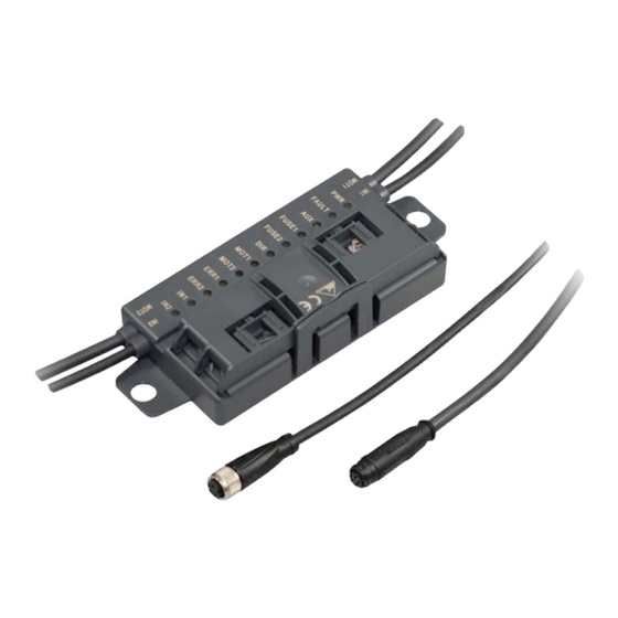
- Page 1 VBA-4E4A-G20-ZEJ/M3L-P9 AS-Interface motor control module Manual...
- Page 2 Phone: +49 621 776 - 0 E-mail: info@de.pepperl-fuchs.com North American Headquarters Pepperl+Fuchs Inc. 1600 Enterprise Parkway Twinsburg, Ohio 44087 Phone: +1 330 425-3555 E-mail: sales@us.pepperl-fuchs.com Asia Headquarters Pepperl+Fuchs Pte. Ltd. P+F Building 18 Ayer Rajah Crescent Singapore 139942 Phone: +65 6779-9091 E-mail: sales@sg.pepperl-fuchs.com https://www.pepperl-fuchs.com...
-
Page 3: Table Of Contents
VBA-4E4A-G20-ZEJ/M3L-P9 Contents Introduction........................ 4 Content of this Document ................4 Target Group, Personnel ................4 Symbols Used ....................5 Intended Use ....................5 General Safety Information................6 Declaration of Conformity................6 Certificates and approvals..................7 UL Information ....................7 Product Description ....................8 Use and application.................. -
Page 4: Introduction
VBA-4E4A-G20-ZEJ/M3L-P9 Introduction Introduction Content of this Document This document contains information required to use the product in the relevant phases of the product life cycle. This may include information on the following: • Product identification • Delivery, transport, and storage •... -
Page 5: Symbols Used
VBA-4E4A-G20-ZEJ/M3L-P9 Introduction Symbols Used This document contains symbols for the identification of warning messages and of informative messages. Warning Messages You will find warning messages, whenever dangers may arise from your actions. It is mandatory that you observe these warning messages for your personal safety and in order to avoid prop- erty damage. -
Page 6: General Safety Information
In the event of any serious errors, stop using the device. Secure the device against unintended operation. To have the device repaired, return it to your local Pepperl+Fuchs representative or your sales center. Note Disposal Electronic waste is dangerous. -
Page 7: Certificates And Approvals
VBA-4E4A-G20-ZEJ/M3L-P9 Certificates and approvals Certificates and approvals UL Information Technical Data and Environmental Conditions This device is for indoor use only. This device may be operated in altitudes up to 2000 m. The ambient temperature range is from -25 °C to +70 °C. -
Page 8: Product Description
Product Description Use and application The VBA-4E4A-G20-ZEJ/M3L-P9 motor control module is an AS-Interface connection module for controlling 1 or 2 DC roller motors. The module is optimized for Interroll EC310 motors, but can also be used for compatible DC motors. -
Page 9: Displays And Operating Elements
VBA-4E4A-G20-ZEJ/M3L-P9 Product Description 135.5 27.5 Figure 3.2 Housing dimensions Displays and operating elements YELLOW BLACK MOT1 MOT2 Figure 3.3 Status indicators on the motor control module The operating state of the motor control module is displayed via 12 LEDs. Status indicators for AS-Interface and power supply The PWR LED and the FAULT LED show the AS-Interface operating state. - Page 10 VBA-4E4A-G20-ZEJ/M3L-P9 Product Description Display of the AUX External auxiliary voltage supply AUX LED Red/green Status Green on AUX external auxiliary voltage is OK Red on AUX external auxiliary voltage is inverted AUX external auxiliary voltage is missing Status indicators for motor fuses The FUSE1 LED for motor 1 and the FUSE2 LED for motor 2 show the status of the power sup- plied to the motors.
-
Page 11: Interfaces And Connections
VBA-4E4A-G20-ZEJ/M3L-P9 Product Description Motor direction of rotation indicator LED DIR Yellow Status Direction of rotation to the right (in accordance with EC310) Direction of rotation to the left (in accordance with EC310) Table 3.4 Status indicators for IN1, IN2 sensors The IN1 LED for input 1 and IN2 LED for input 2 show the switch states of the inputs. -
Page 12: Accessories
VBA-4E4A-G20-ZEJ/M3L-P9 Product Description Motor supply from auxiliary current The motors are supplied with power directly from the AUX external auxiliary current and this cannot be switched. The voltage is always on contacts 1 and 3 of the 5-pin M8 connector. -
Page 13: Installation
Retain the original packaging in case the device must be stored or shipped again at a later date. Should you have any questions, please contact Pepperl+Fuchs. Connecting the AS-Interface and Auxiliary Power Flat Cable The motor control module is connected to the AS-Interface network and the AUX auxiliary power via the AS-Interface flat cable. - Page 14 VBA-4E4A-G20-ZEJ/M3L-P9 Installation Close the cable guide. It must engage securely in the locking bracket (1). The metal mandrels contact the strands in the flat cables. YELLOW BLACK Figure 4.1 Connecting Flat Cables on the Narrow Side Connecting Flat Cables on the Wide Side The profile edge is not visible from above.
- Page 15 VBA-4E4A-G20-ZEJ/M3L-P9 Installation YELLOW BLACK Figure 4.2 Connecting flat cables on the wide side (profile edge as dotted line) Flat Cable Inserted Incorrectly The figure below shows an incorrectly inserted flat cable. The profile edge (2) does not point to the motor control module; the flat cable is therefore inserted with reverse polarity. The flat cable is located on the reverse polarity protection (1) with a curvature, which means that the cable guide cannot be closed completely (mechanical reverse polarity protection).
-
Page 16: Connecting Motors And Sensors
VBA-4E4A-G20-ZEJ/M3L-P9 Installation Connecting motors and sensors IN1 & IN2 AS-Interface + AS-Interface - (n.c.) MOT1 & MOT2 FUSE MOT+ FAULT ERROR SPEED MOT- AUX+ AUX- Figure 4.4 Connection wiring diagram for motors and sensors... -
Page 17: Commissioning
VBA-4E4A-G20-ZEJ/M3L-P9 Commissioning Commissioning AS-Interface slaves are usually addressed with a handheld. Connect the adapter cable VAZ- PK/G20-1M-V1-G to the handheld VBP-HH1-V3.0. AS-Interface communication Assignment of AS-Interface data bits 4 data bits are available for communication to take place between the motor control module and the master. - Page 18 VBA-4E4A-G20-ZEJ/M3L-P9 Commissioning Switching the motor direction of rotation (DO2) You can switch the direction of rotation of the motors using the DIR control signal. The direction of rotation signal applies to both motors. To control the direction of rotation, you must parame- terize data bit DO2 accordingly.
-
Page 19: Configuring The Start/Stop Ramps
VBA-4E4A-G20-ZEJ/M3L-P9 Commissioning Parameter bits P0, P1 Speed signal U Parameter bit DO0 (MOT1) or DO1 (MOT2) Fast (D3 = 0) Slow (D3 = 1) < 1 V < 1 V 6.44 V 3.96 V 7.26 V 4.28 V 8.5 V 4.78 V... - Page 20 VBA-4E4A-G20-ZEJ/M3L-P9 Commissioning Predefined start/stop ramps Ramp number Ramp duration No ramp (default setting) 50 ms 100 ms 200 ms 300 ms 500 ms 1000 ms 1500 ms Table 5.9 The ramp is not effective if the direction of rotation signal is switched when the motor is active.
- Page 21 VBA-4E4A-G20-ZEJ/M3L-P9 Commissioning Note Sequence for command transmission For each step, you generally send the data value via DO0 ... D03 first and then the parameter value P0 ... P2. The following table shows the contexts of communication between the master and motor control module.
- Page 22 VBA-4E4A-G20-ZEJ/M3L-P9 Commissioning Troubleshooting during configuration If a fault occurs during the 9-step configuration process, the following table describes the behavior of the motor control module. Fault scenarios Step Possible fault Motor control module reaction 1 ... 6 • Incorrect data or parameter values or Motor control module remains in normal mode.
-
Page 23: Troubleshooting
VBA-4E4A-G20-ZEJ/M3L-P9 Troubleshooting Troubleshooting Fault information and remedy LED status indi- Error cator Possible cause Remedy No data commu- PWR off AS-Interface voltage is missing or is Check AS-Interface wiring nication with AS- inverted Interface master PWR flashes and Module address is 0... - Page 24 Pepperl+Fuchs Quality Download our latest policy here: www.pepperl-fuchs.com/quality www.pepperl-fuchs.com © Pepperl+Fuchs · Subject to modifications Printed in Germany / DOCT-6524A...
Need help?
Do you have a question about the VBA-4E4A-G20-ZEJ/M3L-P9 and is the answer not in the manual?
Questions and answers