
Related Manuals for Pepperl+Fuchs VBA-2E-G11-I/U/PT100-F


Summary of Contents for Pepperl+Fuchs VBA-2E-G11-I/U/PT100-F
- Page 1 FACTORY AUTOMATION MANUAL VBA-2E-G11-I/U/PT100-F VBA-2E-G11-I/U/PT100-V1 AS-Interface Analog Module Spec 2.1...
- Page 2 VBA-2E-G11-I/U/PT100-* With regard to the supply of products, the current issue of the following document is ap- plicable: The General Terms of Delivery for Products and Services of the Electrical Indus- try, published by the Central Association of the Electrical Industry (Zentralverband Elektrotechnik und Elektroindustrie (ZVEI) e.V.) in its most recent version as well as the supplementary clause: "Expanded reservation of proprietorship"...
-
Page 3: Table Of Contents
VBA-2E-G11-I/U/PT100-* Introduction................. 4 Declaration of Conformity............5 Safety ................... 6 Symbols relevant to safety..............6 Intended Use ..................6 General Safety Instructions ..............6 Product Description ..............7 Displays and Controls ................. 7 Connections ..................8 Automatic Detection of the Sensor Type ........... 9 Pt100 temperature sensor.............. -
Page 4: Introduction
Introduction Introduction Congratulations You have chosen a device manufactured by Pepperl+Fuchs. Pepperl+Fuchs develops, produces and distributes electronic sensors and interface modules for the market of automation technology on a worldwide scale. Before you install this device and put it into operation, please read the operating instructions thoroughly. -
Page 5: Declaration Of Conformity
All products were developed and manufactured under observance of the applicable European standards and guidelines. Note! A Declaration of Conformity can be requested from the manufacturer. The product manufacturer, Pepperl+Fuchs GmbH, 68307 Mannheim, has a certified quality assurance system that conforms to ISO 9001. ISO9001... -
Page 6: Safety
If serious faults occur, stop using the device. Secure the device against inadvertent operation. In the event of repairs, return the device to your local Pepperl+Fuchs representative or sales office. The connection of the device and maintenance work when live may only be carried out by a qualified electrical specialist. -
Page 7: Product Description
VBA-2E-G11-I/U/PT100-* Product Description Product Description Displays and Controls AS-i FAULT VBA-2E-G11-I/U/PT100 Figure 4.1 Display and control elements The VBA-2E-G11-I/U/PT100-* analog module is equipped with the following displays and controls: LED Indicator AS-i/FAULT LED Status indication; multicolor LED Green: normal mode Red: communication error Flashing yellow/red: address 0 Flashing green/red: peripheral fault... -
Page 8: Connections
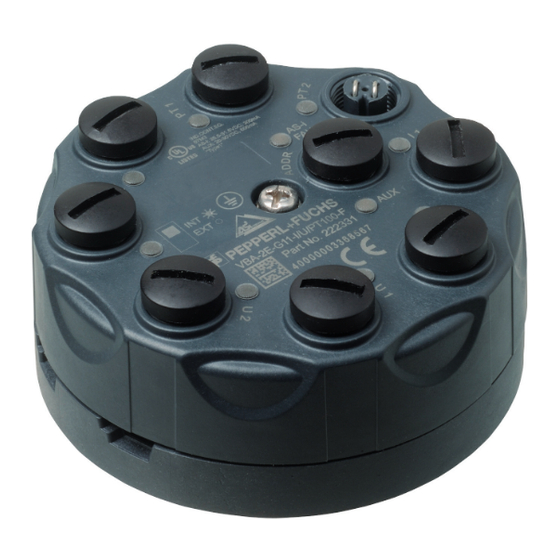
Connections VBA-2E-G11-I/U/PT100-F AS-i FAULT VBA-2E-G11-I/U/PT100 Figure 4.2 Connections VBA-2E-G11-I/U/PT100-F The VBA-2E-G11-I/U/PT100-F analog module is equipped with the following connections: Pt100 inputs : functional ground Current inputs M12 round plug connector Voltage inputs Addressing socket Low voltage switch socket, 1.3 mm... -
Page 9: Automatic Detection Of The Sensor Type
VBA-2E-G11-I/U/PT100-* Product Description Note! Switching Off the Second Channel Figure 4.4 Input PT2 bridge Two bridges are plugged in at the PT100 input PT2 by default; these bridges are designed to switch off channel 2. Remove the bridges to use channels 1 and 2. The bridges must be plugged in and disconnected only when the module is de-energized! Automatic Detection of the Sensor Type The VBA-2E-G11-I/U/PT100-* analog input module automatically detects which sensor type is... -
Page 10: Pt100 Temperature Sensor
VBA-2E-G11-I/U/PT100-* Product Description Pt100 temperature sensor Pt100 temperature sensors are platinum resistance thermometers complying with standard IEC 751 / DIN EN 60751. In this standard, various values of the temperature sensor are defined. The nominal resistance of the Pt100 is 100 , measured at 0 °C. Furthermore, as well as other values, the mean temperature coefficient ... -
Page 11: Installation
0.4 Nm. Connecting the AS-Interface VBA-2E-G11-I/U/PT100-F The VBA-2E-G11-I/U/PT100-F is connected with the AS-Interface network via the yellow flat cable. The external auxiliary power source U is connected to the module via the black flat cable where required. - Page 12 VBA-2E-G11-I/U/PT100-* Installation 3. If the module is to be powered via an external auxiliary power source U , place the black flat cable in the channel labeled AUX. Set the INT/EXT switch to EXT. If the module is to be powered solely by the AS-Interface, place the flat cable seal (VAZ-FK- S-BK-SEAL) in the channel labeled AUX.
-
Page 13: Connecting The Sensors
VBA-2E-G11-I/U/PT100-* Installation Connecting the Sensors Inputs: Connection examples: Current input I1/I2 2-wire 3-wire 4-wire 24 V Sig+ Sig- 3-wire 4-wire Voltage input U1/U2 24 V Sig+ Sig- Pt100 input PT1/PT2 Pt100 Pt100 2-wire 4-wire ϑ ϑ Figure 5.2 2-wire, 3-wire, and 4-wire sensors can be connected to the VBA-2E-G11-I/U/PT100-* module. Suitable for various connection scenarios see Figure 5.2 on page 13. -
Page 14: Commissioning
To operate the VBA-2E-G11-I/U/PT100-* in an AS-Interface network, you must assign a suitable address to the AS-Interface slave. The AS-Interface VBP-HH1-V3.0 handheld device by Pepperl+Fuchs or an AS-Interface master can be used to assign addresses. The VBA-2E-G11-I/U/PT100-* module is a standard slave as defined by specification 2.1. - Page 15 VBA-2E-G11-I/U/PT100-* Commissioning Parameter P2: Peripheral Fault Default value P2=1, active Parameter P2 is used to switch notification of a peripheral fault in the event of a measuring overrange on or off (see chapter 9). If notifications are activated, the AS-i/FAULT LED flashes in the event of a peripheral fault, and a notification is sent to the master.
-
Page 16: Troubleshooting
■ EXT) If none of these potential solutions correct the peripheral fault, please contact Pepperl+Fuchs. Cause and elimination of a channel fault If channel 2 is not transferred and the LED at the connection of the relevant input of channel 2 is not illuminated, channel 2 is not activated. -
Page 17: Dimensions
VBA-2E-G11-I/U/PT100-* Appendix A Appendix A Dimensions Type VBA-2E-G11-I/U/PT100-F 85 mm 35 mm VBA-2E-G11-I/U/PT100-V1 85 mm 35 mm 11 mm Technical Data General Data Slave type Standard slave AS-Interface specification V3.0 Required master V2.1 specification UL file number E87056 Display/Controls AS-i/FAULT LED Status indication;... - Page 18 VBA-2E-G11-I/U/PT100-* Appendix A Input Number/type Two analog inputs Current: 4 mA ... 20 mA/4 mA ... 20 mA Voltage: 0 V ... 10 V Pt100: -200 °C ... 850 °C Power supply From AS-Interface (switch setting INT, basic setting) or from auxiliary power source U (switch setting EXT) Current rating...
- Page 19 Ambient conditions Ambient temperature -25 °C ... 70 °C (-13 °F ... 158 °F) Storage temperature -25 °C ... 85 °C (-13 °F ... 185 °F) Mechanical Data Device VBA-2E-G11-I/U/PT100-F VBA-2E-G11-I/U/PT100-V1 Connection AS-Interface/U : insulation AS-Interface/U : M12 round piercing technology, yellow flat...
-
Page 20: Analog Input Module Measurement Ranges
VBA-2E-G11-I/U/PT100-* Appendix B Appendix B Analog Input Module Measurement Ranges Current Input Measurement Ranges The measurement range of the current input can be set via AS-Interface parameter P3: P3=1, nominal range 4 mA ... 20 mA ■ P3=0, nominal range 0 mA ... 20 mA ■... -
Page 21: Delay Times
VBA-2E-G11-I/U/PT100-* Appendix B Caution! Maximum input voltage The input voltage at the voltage input must not exceed 50 V. Pt100 Input Measurement Ranges Pt100: -200 °C ... 850 °C Input signal [V] Display on the master Input LED > 884°C 32767 Flashing Above threshold... - Page 22 VBA-2E-G11-I/U/PT100-* Appendix B Module Analog-to-digital Analog-to-digital Analog-to-digital Analog-to-digital conversion conversion conversion conversion Channel 1 Channel 2 Channel 1 Channel 2 Transmission Transmission Transmission Channel 1 Channel 2 Channel 1 ~ Conversion time x 3 Transmission time Network Figure 9.2 Conversion time < Transmission time Conversion time The conversion time is the time that the module requires to convert an analog signal into a digital value.
- Page 23 VBA-2E-G11-I/U/PT100-* Appendix B...
- Page 24 Twinsburg, Ohio 44087 · USA Tel. +1 330 4253555 E-mail: sales@us.pepperl-fuchs.com Asia Pacific Headquarters Pepperl+Fuchs Pte Ltd. Company Registration No. 199003130E Singapore 139942 Tel. +65 67799091 E-mail: sales@sg.pepperl-fuchs.com www.pepperl-fuchs.com Subject to modifications / TDOCT2097E_ENG Copyright PEPPERL+FUCHS • Printed in Germany 02/2014...
Need help?
Do you have a question about the VBA-2E-G11-I/U/PT100-F and is the answer not in the manual?
Questions and answers