
Related Manuals for Pepperl+Fuchs VBA-4E3A-G20-ZEL/M1L-P6


Summary of Contents for Pepperl+Fuchs VBA-4E3A-G20-ZEL/M1L-P6
- Page 1 FACTORY AUTOMATION MANUAL VBA-4E3A-G20- ZEL/M1L-P2 AS-Interface Motor Control Module...
- Page 2 VBA-4E3A-G20-ZEL/M1L-P2 With regard to the supply of products, the current issue of the following document is ap- plicable: The General Terms of Delivery for Products and Services of the Electrical Indus- try, published by the Central Association of the Electrical Industry (Zentralverband Elektrotechnik und Elektroindustrie (ZVEI) e.V.) in its most recent version as well as the supplementary clause: "Expanded reservation of proprietorship"...
-
Page 3: Table Of Contents
VBA-4E3A-G20-ZEL/M1L-P2 Introduction................. 4 Declaration of Conformity............5 Safety ................... 6 Symbols Relevant to Safety ..............6 Intended Use ..................6 General Safety Information..............6 Product Description ..............7 Use and Application................7 Housing....................8 Indicators and Operating Controls............. 9 Interfaces and Connections.............. 11 Installation................. -
Page 4: Introduction
Introduction Introduction Congratulations You have chosen a device manufactured by Pepperl+Fuchs. Pepperl+Fuchs develops, produces and distributes electronic sensors and interface modules for the market of automation technology on a worldwide scale. Please read the operating instructions carefully before installing this device and putting it into operation. -
Page 5: Declaration Of Conformity
All products were developed and manufactured under observance of the applicable European standards and guidelines. Note! A Declaration of Conformity can be requested from the manufacturer. The product manufacturer, Pepperl+Fuchs GmbH, 68307 Mannheim, has a certified quality assurance system that conforms to ISO 9001. ISO9001... -
Page 6: Safety
If serious faults occur, stop using the device. Secure the device against inadvertent operation. In the event of repairs, return the device to your local Pepperl+Fuchs representative or sales office. The connection of the device and maintenance work when live may only be carried out by a qualified electrical specialist. -
Page 7: Product Description
VBA-4E3A-G20-ZEL/M1L-P2 Product Description Product Description Use and Application The VBA-4E3A-G20-ZEL/M1L-P2 motor control module is an AS-Interface connection module for controlling one or two DC roller motors. The module is optimized for type Interroll EC310 motors, but can be used for compatible DC motors as well. To record statuses in the field environment, the module has two inputs for three-wire sensors with positive-switching output (PNP) or for mechanical contacts. -
Page 8: Housing
VBA-4E3A-G20-ZEL/M1L-P2 Product Description Essential function and application characteristics of the motor control module are: Compact housing for direct mounting in support profiles or cable ducts Connection of the motors/sensors via cable outputs with M8 connectors Insulation piercing technology with gold-plated contact pins for contacting the AS- Interface flat cable Function displays for the bus, external auxiliary power, status information, inputs, and outputs... -
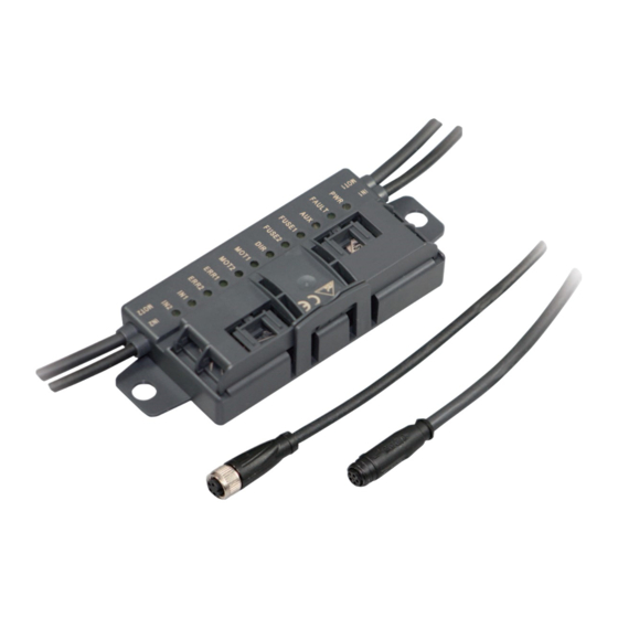
Page 9: Indicators And Operating Controls
VBA-4E3A-G20-ZEL/M1L-P2 Product Description Indicators and Operating Controls YELLOW BLACK MOT1 MOT2 Figure 4.3 Status indications on the motor control module. The operating status of the motor control module is displayed via 12 LEDs. Note! Additional Flashing Codes during Module Configuration The following status information relates only to the normal mode of the motor control module. - Page 10 VBA-4E3A-G20-ZEL/M1L-P2 Product Description Status Indications for AS-Interface and Power Supply The PWR LED and the FAULT LED show the AS-Interface operating status. Various error statuses are displayed as a collective error message "Peripheral fault." Display of the AS-Interface Operating Statuses LED PWR LED FAULT Green...
-
Page 11: Interfaces And Connections
VBA-4E3A-G20-ZEL/M1L-P2 Product Description Status Indications for Motors MOT1, MOT2 The MOT1, MOT2, ERR 1, ERR2, and DIR LEDs display information about the operating statuses of the respective motor. Motor Activity Indicators LED MOT1 LED MOT2 Yellow Status Motor is in operation Motor is off Motor Fault Indicators LED ERR1... - Page 12 VBA-4E3A-G20-ZEL/M1L-P2 Product Description The following AS-Interface cable types are available with UL Recognized approval: AS-Interface Cable Types with UL Approval Pepperl+Fuchs Sheathing material/ Designation Color wire insulation Cross-section UL "Cable Style" Approval VAZ-FK-R-YE Yellow TPE/TPE 2x 1.5 mm 2103 VAZ-FK-R-BK...
-
Page 13: Installation
Retain the original packaging in case the device must be stored or shipped again at a later date. Should you have any questions, please direct them to Pepperl+Fuchs. Connecting the AS-Interface and Auxiliary Power Flat Cable The motor control module is connected to the AS-Interface network and the AUX auxiliary power via the AS-Interface flat cable. - Page 14 VBA-4E3A-G20-ZEL/M1L-P2 Installation Connecting Flat Cables on the Narrow Side The profile edge is visible from above. 1. Open the cable guide. To do this, push the locking bracket (1) slightly to one side. 2. Insert the black AUX flat cable with the profile edge (4) to the motor control module into the lower guide (see the module tag "Black AUX").
- Page 15 VBA-4E3A-G20-ZEL/M1L-P2 Installation Connecting Flat Cables on the Wide Side The profile edge is not visible from above. For orientation purposes in the figure below, the edge is shown as a hidden edge drawn with a dotted line. 1. Open the cable guide. To do this, push the locking bracket (1) slightly to one side. 2.
-
Page 16: Connecting Motors And Sensors
VBA-4E3A-G20-ZEL/M1L-P2 Installation Flat Cable Inserted Incorrectly The figure below shows an incorrectly inserted flat cable. The profile edge (2) does not point to the motor control module; the flat cable is therefore inserted with reverse polarity. The flat cable is located on the reverse polarity protection (1) with a curvature, which means that the cable guide cannot be closed completely (mechanical reverse polarity protection). -
Page 17: Commissioning
VBA-4E3A-G20-ZEL/M1L-P2 Commissioning Commissioning AS-Interface Communication Assigning the AS-Interface Data Bits Four data bits are available for communication to take place between the motor control module and the master. Three data bits are available for controlling the motors. The following designations apply below: DI0...DI3 for AS-Interface input data (motor control module to master) DO0...DO2 for AS-Interface output data (master to motor control module) DI0...DI03 Motor Control Module to Master... - Page 18 VBA-4E3A-G20-ZEL/M1L-P2 Commissioning Logical 1, according to EC310, corresponds to direction of rotation to the right. The motor control module switches the DIR control signal to AUX level. DO2 Data Bit Data bit Status Function DIR direction of rotation signal LED DIR Direction of rotation left High impedance, approx.
-
Page 19: Configuration Of The Start/Stop Ramps
VBA-4E3A-G20-ZEL/M1L-P2 Commissioning DI0, DI1 Data Bits Data bit Status Motor error status Motor error signal ERROR LED ERR1/2 ≤ 1.2 V, I ≥ 40 µA ERR1: off No fault in motor 1 ERROR ERROR Fault in motor 1 High impedance ERR1: on Or motor 1 is not connected Or fuse is defective... - Page 20 VBA-4E3A-G20-ZEL/M1L-P2 Commissioning The ramp is not effective if the direction of rotation signal is switched when the motor is active. In this case, the direction of rotation is reversed immediately. Note! Default Setting on Delivery On delivery, ramp no. 0 (no ramp) is the default setting. Configuring Start/Stop Ramps To adjust a start/stop ramp, you must change the motor control module to configuration mode.
- Page 21 VBA-4E3A-G20-ZEL/M1L-P2 Commissioning Sequence for Configuring a Start/Stop Ramp Send the following data values and parameter values to the motor control module: 1. In accordance with steps one to six, for each step send the data value "4" via DO0...DO2 and then via P0...P2, a value of the parameter string 3,1,6,3,1,6 one after the other.
-
Page 22: Troubleshooting
VBA-4E3A-G20-ZEL/M1L-P2 Troubleshooting Troubleshooting Fault Information and Remedy Fault LED display Possible cause Remedy No data PWR off AS-Interface voltage is missing or Check AS-Interface wiring communication has reverse polarity with AS-Interface PWR flashes and Module address is 0 Program module address master FAULT on PWR on and... - Page 23 Twinsburg, Ohio 44087 · USA Tel. +1 330 4253555 E-mail: sales@us.pepperl-fuchs.com Asia Pacific Headquarters Pepperl+Fuchs Pte Ltd. Company Registration No. 199003130E Singapore 139942 Tel. +65 67799091 E-mail: sales@sg.pepperl-fuchs.com www.pepperl-fuchs.com Subject to modifications / DOCT4759 Copyright PEPPERL+FUCHS • Printed in Germany 05/2015...
Need help?
Do you have a question about the VBA-4E3A-G20-ZEL/M1L-P6 and is the answer not in the manual?
Questions and answers