
Subscribe to Our Youtube Channel
Related Manuals for Pepperl+Fuchs VBA-2A-KE5-IL/UL


Summary of Contents for Pepperl+Fuchs VBA-2A-KE5-IL/UL
- Page 1 FACTORY AUTOMATION MANUAL VBA-2A-KE5-IL/UL, VBA-4A-KE5-IJL/UJL AS-Interface Analog Modules Spec 2.1...
- Page 2 VBA-2A-KE5-IL/UL, VBA-4A-KE5-IJL/UJL With regard to the supply of products, the current issue of the following document is ap- plicable: The General Terms of Delivery for Products and Services of the Electrical Indus- try, published by the Central Association of the Electrical Industry (Zentralverband Elektrotechnik und Elektroindustrie (ZVEI) e.V.) in its most recent version as well as the...
-
Page 3: Table Of Contents
Product Description ..............8 Intended Use ..................8 Displays and Operating Elements ............8 Connections ..................10 Configuring the Output Function on the VBA-2A-KE5-IL/UL ..10 Configuring the Output Function on the VBA-4A-KE5-IJL/UJL ..11 Resetting/Restarting Automatic Detection ........12 Installation................. 13 Storage and Transport ............... - Page 4 VBA-2A-KE5-IL/UL, VBA-4A-KE5-IJL/UJL Appendix A................19 Value Ranges of the Analog Output Modules........19 Delay Times..................19...
-
Page 5: Introduction
VBA-2A-KE5-IL/UL, VBA-4A-KE5-IJL/UJL Introduction Introduction Content of this Document This document contains information required to use the product in the relevant phases of the product life cycle. This may include information on the following: Product identification Delivery, transport, and storage Mounting and installation... -
Page 6: Symbols Used
VBA-2A-KE5-IL/UL, VBA-4A-KE5-IJL/UJL Introduction Symbols Used This document contains symbols for the identification of warning messages and of informative messages. Warning Messages You will find warning messages, whenever dangers may arise from your actions. It is mandatory that you observe these warning messages for your personal safety and in order to avoid property damage. -
Page 7: Certificates And Approvals
VBA-2A-KE5-IL/UL, VBA-4A-KE5-IJL/UJL Certificates and Approvals Certificates and Approvals UL Information Technical Data and Environmental Conditions This device is for indoor use only. This device may be operated in altitudes up to 2000 m. The ambient temperature range is from -25 °C to +70 °C. -
Page 8: Product Description
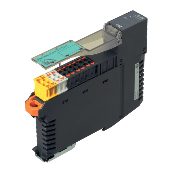
Product Description Intended Use The VBA-2A-KE5-IL/UL features two analog outputs. These outputs can be configured as current outputs (0 mA ... 20 mA) or as voltage outputs (0 V ... 10 V). The outputs are configured as current outputs by default. The outputs are supplied via the external auxiliary voltage. - Page 9 VBA-2A-KE5-IL/UL, VBA-4A-KE5-IJL/UJL Product Description LED Indicators PWR LED AS-Interface voltage; green LED Green: OK status Flashing green: address 0 or peripheral fault FAULT LED Fault indication; red LED Red: communication error or address is 0 Red flashing: peripheral fault AUX LED External auxiliary voltage U ;...
-
Page 10: Connections
Auxiliary voltage; both AUX+ terminals and both AUX- terminals are bridged in AUX- the terminal block. Configuring the Output Function on the VBA-2A-KE5-IL/UL Use the parameter bits P1 and P3 or the two jumpers CON1 and CON2 to configure the function of the outputs. -
Page 11: Configuring The Output Function On The Vba-4A-Ke5-Ijl/Ujl
VBA-2A-KE5-IL/UL, VBA-4A-KE5-IJL/UJL Product Description O1 voltage output, O2 current output Parameter bits: P1=0; P3=1 Jumpers: CON1 CON- CON2 CON- O1 current output, O2 voltage output Parameter bits: P1=1; P3=0 Jumpers: CON1 CON- CON2 CON- 2 x voltage outputs Parameter bits: P1=0; P3=0... -
Page 12: Resetting/Restarting Automatic Detection
VBA-2A-KE5-IL/UL, VBA-4A-KE5-IJL/UJL Product Description Jumpers: CON1 CON- CON2 CON- Automatic Detection Parameter bits: P1=1; P3=1->0 Jumpers: CON1 CON- CON2 CON- A test signal records the input resistance of a connected actuator. If the measured input resistance value is > approx. 2 kΩ, the corresponding output is configured as a voltage output. -
Page 13: Installation
Retain the original packaging in case the device must be stored or shipped again at a later date. Should you have any questions, please contact Pepperl+Fuchs. Mounting Mount the module by snapping it onto a 35 mm DIN rail. -
Page 14: Connecting Actuators
VBA-2A-KE5-IL/UL, VBA-4A-KE5-IJL/UJL Installation Connecting Actuators You can connect 2-, 3-, and 4-wire sensors to the VBA-4E-KE5-IL. For various connection options, see Figure 4.2 on page 14 and see Figure 4.3 on page 14. Actuator supply via the module from AS-Interface (VBA-4A-KE5-IJL/UJL only) or... -
Page 15: Commissioning
The data value is transmitted as defined by AS-Interface profile 7.3. Parameterization The following parameters can be configured: Program the parameters using an AS-Interface master, with the VAZ-SW-ACT32 AS-i Control Tools from Pepperl+Fuchs, or with the VBP- HH1-V3.0 handheld device. Parameter P0: Watchdog Default value P0=1, active Parameter P0 is used to activate the "watchdog"... - Page 16 Default value P3=1 Parameter P3 is used to select the output mode for the analog outputs. VBA-2A-KE5-IL/UL: Parameter P3 selects current mode or voltage mode for output O2. VBA-4A-KE5-IJL/UJL: Parameter P3 activates automatic load detection (automatic mode) for outputs O1 ... O4.
- Page 17 VBA-2A-KE5-IL/UL, VBA-4A-KE5-IJL/UJL Commissioning Configuration via Parameters/Jumpers Parameter VBA-4A-KE5-IJL/UJL VBA-2A-KE5-IL/UL Jumpers Output mode Output mode 4 current outputs 2 current outputs 4 voltage outputs O1 voltage output/O2 CON1 CON- Automatic mode current output CON2 CON- Reserved O1 current output/O2 voltage output...
-
Page 18: Troubleshooting
Check the auxiliary voltage (VBA-4A-KE5-IJL/UJL: AUX switch position) If none of these potential solutions correct the peripheral fault, please contact Pepperl+Fuchs. Causes and Elimination of a Actuator Fault The following causes may prevent connected actuators being activated with the correct signal values. - Page 19 VBA-2A-KE5-IL/UL, VBA-4A-KE5-IJL/UJL Appendix A Appendix A Value Ranges of the Analog Output Modules Value Ranges for Current Outputs Current: 0 mA ... 20 mA Data sent by master Output signal [mA] Output LED > 23000 Above threshold (peripheral fault) 20001 23000 20.001 ...
- Page 20 VBA-2A-KE5-IL/UL, VBA-4A-KE5-IJL/UJL Appendix A Rise Time The rise time is the time required by the module to reach and maintain the target value at the analog output. For a resistive load, the rise time is At the current output: 1.5 ms At the voltage output: 2.5 ms...
- Page 21 Twinsburg, Ohio 44087 · USA Tel. +1 330 4253555 E-mail: sales@us.pepperl-fuchs.com Asia Pacific Headquarters Pepperl+Fuchs Pte Ltd. Company Registration No. 199003130E Singapore 139942 Tel. +65 67799091 E-mail: sales@sg.pepperl-fuchs.com www.pepperl-fuchs.com Subject to modifications / DOCT-5807A Copyright PEPPERL+FUCHS • Printed in Germany 07/2018...
Need help?
Do you have a question about the VBA-2A-KE5-IL/UL and is the answer not in the manual?
Questions and answers