
Related Manuals for CHAINTECH 7NJS Ultra


Summary of Contents for CHAINTECH 7NJS Ultra
- Page 1 CHAINTECH 7NJS Ultra AMD Socket A NVIDIA nForce 2 Ultra 400 + MCP-T ATX Motherboard User's Guide Version 4.0...
- Page 2 According to 47 CFR, Parts 2 and 15 of the FCC Rules The following designated product: EQUIPMENT: MAINBOARD MODEL NO.: 7NJS Ultra is a Class B digital device that complies with 47 CFR Parts 2 and 15 of the FCC Rules. Operation is subject to the following two conditions: 1.
- Page 3 Federal Communications Commission Statement This device complies with FCC Rules Part 15. Operation is subject to the following two conditions: * This device may not cause harmful interference. * This device must accept any interference received, including interference that may cause undesired operation.
-
Page 4: Table Of Contents
Contents CHAPTER 1 INTRODUCTION ........... 1 1 . 1 P ..............1 RODUCT PECIFICATIONS 1 . 2 P ................3 ACKAGE ONTENTS 1 . 3 7NJS U ..........6 LTRA OTHERBOARD IAGRAM 1 . 4 7NJS U ..........7 LTRA OTHERBOARD AYOUT CHAPTER 2 HARDWARE SETUP... - Page 5 ............94 REATING RRAYS UTOMATICALLY ..............95 IEWING RIVE SSIGNMENTS .................. 96 ELETING RRAY ............. 98 EBUILDING IRRORED RRAY DDR MEMORY TEST TABLE ..........100 CPU FSB=266MH DDR ................. 100 CPU FSB=333MH DDR ................. 102 HOW TO CONTACT CHAINTECH ....105...
-
Page 7: Chapter 1 Introduction
UltraDMA-100/133 IDE port with RAID 0/1. USB 2.0/1.1 Host Controller One EHCI USB 2.0 Controller and 2 UHCI USB 1.1 Controllers Support total 6 USB 2.0 Ports (USB1.1 compatible). Support USB 2.0 High-Speed Device @480 Mb/s Transfer Rates. 7NJS Ultra User’s Guide... - Page 8 Support 10/100Mb Fast Ethernet or 1/10Mb HomePNA 2.0 with External PHY. Embedded system monitoring 8 external voltage inputs 2 temperatures sensing for CPU and system. 2 Fan speed (CPU and system) monitoring. Boot-Block Flash ROM Award system BIOS support PnP, APM, DMI, ACPI, & Multi-device. 7NJS Ultra User’s Guide...
-
Page 9: Package Contents
- IEEE-1394 8-pin Cable - Zenith Emblem - WOL cable IEEE-1394 ACR daughter card Manual Include: User’s Guide EZ Manual 10. Digidoc 80-Port POST Error Code List 11. CD Box Include: Driver CD Value-pack 2003 12. Thermal grease pack 7NJS Ultra User’s Guide... - Page 10 Chapter 1 Special Features: 1. CBOX™3, Chaintech’s exclusive front panel. Include: USB (1.1 / 2.0 compliant) Ext. ports ∅ 3 . 5 m m ) Earphone ( phone jack ∅ 3 . 5 m m ) MIC – in ( phone jack IEEE-1394 Ext.
- Page 11 - Audio drivers and utilities for DOS/Win9x/NT/XP -nForce Service Pack for Windows OS including Bus Master IDE drivers, AGP VxD, LAN and etc. 4. Value Pack 2003 software pack including Norton AntiVirus, Adobe ActiveShare, Acrobat Reader, Acrobat eBook Reader, Imagemore and AutoSave. 7NJS Ultra User’s Guide...
- Page 12 Chapter 1 1.3 7NJS Ultra Motherboard Diagram 7NJS Ultra User’s Guide...
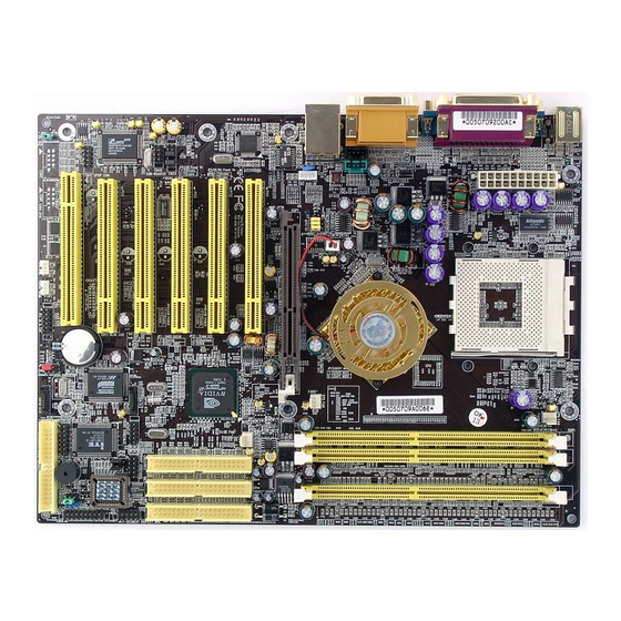
- Page 13 Chapter 1 1.4 7NJS Ultra Motherboard Layout 7NJS Ultra User’s Guide...
-
Page 14: Chapter 2 Hardware Setup
CPU. Failing to install these items may result in overheating and possible burn-out of your CPU. Notes: In order to boot up with a newly installed CPU, AC Power must be switched off before installation. 7NJS Ultra User’s Guide... -
Page 15: Cpu Jumperc
1.6V 64KB 0.18 950 MHz 1.6V 64KB 0.18 1.0G 1.0 GHz 10.0 1.6V 64KB 0.18 1.1G 1.1 GHz 11.0 1.6V 64KB 0.18 1.2G 1.2 GHz 12.0 1.6V 64KB 0.18 1.3G 1.3 GHz 13.0 1.6V 64KB 0.18 7NJS Ultra User’s Guide... - Page 16 256KB 0.18 1300MHz 1400 14.0 1.75V 256KB 0.18 1400MHz 1000 1.75V 256KB 0.18 1000MHz 1113 1.75V 256KB 0.18 1113MHz 1200 1.75V 256KB 0.18 1200MHz 1333 10.0 1.75V 256KB 0.18 1333MHz 1400 10.5 1.75V 256KB 0.18 1400MHz 7NJS Ultra User’s Guide...
- Page 17 1833MHz 2500+ 11.0 1.65V 512KB 0.13 1917MHz 2600+ 11.5 1.65V 512KB 0.13 2075MHz 2800+ 12.5 1.65V 512KB 0.13 2167MHz 3000+ 13.0 1.65V 512KB 0.13 2100MHz 3000+ 10.5 1.65V 512KB 0.13 2200MHz 3200+ 11.0 1.65V 512KB 0.13 7NJS Ultra User’s Guide...
-
Page 18: Main Memoryc
512 MB 1.0 GB DDR 1 DDR 2 DDR 3 Note: For maximized Dual-channel (128-bit) result, you must install one of your two memory modules on DDR3. Memory compatibility test please refer to Appendix DDR Memory Test. 7NJS Ultra User’s Guide... - Page 19 Keyboard Power on Function Jumper CN5 / 5A Wake on LAN / Modem Connector IR / CIR Connector JP23 Green LED Mode Jumper (5V) CN17 Blue LED Connector Chassis Open Alarm Connector Smart Card Reader Connector 7NJS Ultra User’s Guide...
- Page 20 Suspend mode is entered by pressing the Override Power Button, pushing the Green button on your ATX case, or enabling the Power Management and Suspend Mode options in BIOS's Power Management menu. (See section 3.5) 7NJS Ultra User’s Guide...
- Page 21 Full-On. Pushing the button while in Full-On mode for more than [4 seconds] will switch the system completely off. See Over-ride Power Button Operation diagram. 7NJS Ultra User’s Guide...
- Page 22 This 4-pin connector connects to the case-mounted speaker F. HD-LED (IDE Activity LED Connector): The IDE activity LED lights up whenever the system reads/writes to the IDE devices. FD1 (Floppy Disk Connector) This connector is used to connect 34 pins of Floppy. 7NJS Ultra User’s Guide...
- Page 23 Using IDE RAID, the IDE HDD needs to be set to Master, not Slave; otherwise, the HDD can not be detected. For 7NJS Ultra, one/two Serial ATA(s) and one IDE RAID or two Serial ATAs need to be used at the same time.
- Page 24 3. Connect the system's power and then start the system. 4. Enter BIOS's CMOS Setup Utility and choose Load Setup Defaults. Type [Y] and press [enter]. 5. Set the system configuration in the Standard CMOS Setup menu. 7NJS Ultra User’s Guide...
- Page 25 JP8 (On board Audio Enable/Disable): Definition Enable (default) Disable This function allows you to enable or disable the on board audio. You must set the jumper cap to pins 1-2 to enable or set pins 2-3 to disable this function. 7NJS Ultra User’s Guide...
- Page 26 CN2/CN2A (CD-ROM Audio-in Connector): Use the audio cable enclosed with your CD-ROM disk drive to connect the CD-ROM to your motherboard. This will enable your CD-ROM's audio function. CN3 (Auxiliary Audio-in Connector): This connector is for AUX Audio Device. 7NJS Ultra User’s Guide...
- Page 27 This connector must be connected to a 6-channel bracket. CN4C (SPDIF Connector): This connector must be connected to a SPDIF bracket. The DIP switch of SPDIF bracket sets to: 1 OFF, 2 OFF, 3 ON, 4 OFF 7NJS Ultra User’s Guide...
- Page 28 Enable JP6A USB 2/3 JP6B USB 4/5 A USB keyboard hot key or a USB mouse click can turn on this board. You must also set this jumper's cap to pins 2-3 to use this function. 7NJS Ultra User’s Guide...
- Page 29 Simply remove the two jumper caps at pin [5-6] and [9-10] then plug it into the (optional) cable ext. connector. Pin [5-6] and [9-10] are shorted (default) to enable the back panel audio function. 7NJS Ultra User’s Guide...
- Page 30 Chapter 2 CN25 (DigiDoc System Monitoring Display): CBOX3 features CHAINTECH’s exclusive [DigiDoc], the most advance system diagnostic monitoring display. 80-PORT diagnostic display during POST at system boot up! CPU temperature monitoring, your system stays cool always! DigiDoc is the doctor for your system! Please refer to Appendix Digidoc 80-Port POST Error Code List.
- Page 31 Hot Key Power ON option under Wake Up Events in the BIOS's Power Management Setup screen. You must also set this jumper's cap to pins [2-3] to use this function. 7NJS Ultra User’s Guide...
- Page 32 CN5A [WOM (Wake-on-Modem) Connector]: Enable the Power ON by Ring/WOL selection in BIOS's Power Management Setup Menu to use this function. This header is used to connect an add-in modem card which gives WOM capability to the motherboard. 7NJS Ultra User’s Guide...
- Page 33 Select a UART Mode in BIOS's Integrated Peripherals menu the UART port to support IR function. (See section 3.4 Super I/O Device of Integrated Peripherals) JP23 (Green Mode LED): Definition CHAINTECH (default) This cap is to setup Green LED flash mode. (Optional) 7NJS Ultra User’s Guide...
- Page 34 The only difference is that this one is blue while the other is red LED. CN9 (Chassis Open Alarm Connector): This connector provides a buzzer sound when an attempt to open the chassis occurs. Note: Only certain chassis provides this function. 7NJS Ultra User’s Guide...
- Page 35 Chapter 2 CN7 (Smart Card Reader Connector): This connector must be connected to an optional Smart card reader. 7NJS Ultra User’s Guide...
-
Page 36: 1394 Acr Card
ACR slot and press firmly until the card is completely seated on the slot. Secure the card to the chassis with the screw, and put the chassis back on. Set up the BIOS according to section 3.4 7NJS Ultra User’s Guide... -
Page 37: Cbox™ 3 Setup
* Remove CN24 Jumper Caps on motherboard 5-6, 9-10 before installation. USB Cable (10 pin) Front Audio Cable (10 pin) IEEE-1394 Cable (8 pin) 80 Port Display (10 pin) WOL Cable( 3 pin) JP6 (Power Select) VCC5SBY (Default) USB5V Note: Each cable got security-proof. 7NJS Ultra User’s Guide... -
Page 38: Handigator : Function
Next Page in WWW Tab Key Stop browsing Backspace Key Refresh in WWW Mouse Mouse left button Enter Key Mouse right button Previous Track Play/Pause Multimedia Next Track Fast Backward Stop playing Fast Forward .(dot) Volume Up Esc Key 7NJS Ultra User’s Guide... -
Page 39: Chapter 3 Bios Setup Program
Select the desired item by your arrow keys and press enter to make the changes. Operating commands are located at the bottom of this and all other BIOS screens. When a field is highlighted, on-line help information is displayed on the right side of the screen. Figure 3-1 7NJS Ultra User’s Guide... -
Page 40: Standard Cmos S
5-1/4 in], [1.2M, 5-1/4 in], [720k, 3-1/2 in], [1.44M, 3-1/2 in], and [2.88M, 3-1/2 in]. Video: Select the type of video adapter present in your system. You can ignore this setting if you are using a VGA monitor since VGA BIOS automatically configures this setting. 7NJS Ultra User’s Guide... -
Page 41: Eatures
Cache memory is much faster than conventional DRAM system memory. These fields allow you to enable or disable the CPUs Level 1 built-in cache and Level 2 external cache. Both settings are left enabled to significantly increase the performance of your computer. 7NJS Ultra User’s Guide... - Page 42 BIOS setup program. When the Security Option is set to Setup, a password is required to enter the BIOS setup program. (10) APIC Mode: This item can enable or disable the APIC. (Advanced Programmable 7NJS Ultra User’s Guide...
- Page 43 Set to Enabled if you want the Chassis Intrusion Warning message during the BIOS POST procedure. If your computer case has been opened, you should set Disabled and restart. Then the warning message will be cleared. 7NJS Ultra User’s Guide...
- Page 44 This feature allows the system and memory to run at FSB clock speed. Options include 100 MHz (200 MHz) to 250 MHZ (500 MHz). (3) CPU Ratio: It is recommended to keep the default setting for stable system operation. 7NJS Ultra User’s Guide...
- Page 45 (10) AGP Fast Write Capability: Selecting [Enabled] to allow Fast Write Protocol for 8x/4x AGP to function. Not all AGP cards support fast write. (11) System BIOS Cacheable: Enabling this function allows caching of the system BIOS ROM at 7NJS Ultra User’s Guide...
- Page 46 3-1), the screen below is displayed. This sample screen contains the manufacturer's default values for the motherboard. Figure 3-5 Integrated Peripherals Screen (1) IDE Function Setup: Press [Enter] to enter the sub-menu, which contains the following items for advanced control: 7NJS Ultra User’s Guide...
- Page 47 MC97 Modem. CMedia Audio: This feature allows user to select 6 channels function, if that connect one 6ch Expansion kit to motherboard. MAC LAN (nVIDIA): This item allows you to Auto / Disabled the onboard LAN function. 7NJS Ultra User’s Guide...
- Page 48 This item disables or assigns the address of the Game port. Available options are [201] and [209]. Midi Port Address: This item disables or assigns the address of the Midi port. Available options are [300] and [330]. 7NJS Ultra User’s Guide...
-
Page 49: S E T U P
By choosing the Power Management Setup option from the CMOS Setup Utility menu (Figure 3-1), the screen below is displayed. This sample screen contains the manufacturer's default values for the motherboard Figure 3-6 Power Management Setup 7NJS Ultra User’s Guide... - Page 50 (4) HDD Power Down: Shuts down any IDE hard disk drives in the system after a period of inactivity as set in this user configurable field. This feature does not affect SCSI hard drives. 7NJS Ultra User’s Guide...
- Page 51 Software Power-Off function to turn off the computer. POWER ON Function: This control show the PS/2 mouse or keyboard can power on the system. Available settings are [Password], [Hot KEY], [Mouse Move], [Mouse Click], [Any KEY], [BUTTON ONLY] and [Keyboard 98]. 7NJS Ultra User’s Guide...
- Page 52 IRQ & DMA. When set to Auto the system BIOS will refer to the ESCD for all legacy information. ESCD (Extended System Configuration Data) provides a detailed format of the configuration data structures stored in flash memory. Each data structure 7NJS Ultra User’s Guide...
- Page 53 [12], [14] and [15]. FDD IRQ Can Be Free: This function allows user to choose if the FDD IRQ can be freed up. The default setting is Yes and this does not allow the IRQ to be free. 7NJS Ultra User’s Guide...
- Page 54 When the processor reaches the temperature you set, this will shutdown the system. This function only works in ACPI-aware OS (such as Windows 98 / ME / 2000). Available options are [85°C/185°F], [90°C/194°F], [95°C/203°F], and [100°C/210°F]. 7NJS Ultra User’s Guide...
- Page 55 Any attempt to operate beyond product specifications is not recommended. We do not guarantee the damages or risks caused by inadequate operation or beyond product specifications. 7NJS Ultra User’s Guide...
-
Page 56: Setting
BIOS. The user, on the other hand, is only allowed to access the computer's operating system and change the user password in BIOS. Note: that when there is no supervisor password set, the user password controls access to all BIOS settings. 7NJS Ultra User’s Guide... -
Page 57: S E T U P
CMOS memory of the BIOS chip. 3.13 Exit Without Saving Selecting this option and pressing Y followed by the [Enter] key lets you exit the Setup program without recording any new values or changing old ones. 7NJS Ultra User’s Guide... -
Page 58: Ackage Setup
Insert the support CD that come with your motherboard into your CD-ROM drive or double-click the CD drive icon in [My computer] to enter the setup screen. 4.1 Nvidia Driver Package Setup 1.Select [Nvidia Driver Package] 2.Select [Next >] 7NJS Ultra User’s Guide... - Page 59 3.Please select [Yes] to restart computer now or [No] to restart later, and then click on [Finish] to complete the installation. 4.2 C-MEDIA Sound Driver Setup This section provides information on installed audio devices by choosing [Audio Drivers] from the Setup Driver menu. 1.Select [Nvidia Driver Package] 7NJS Ultra User’s Guide...
- Page 60 Chapter 4 2.Select [Audio Drivers] to begin software installation 3. Select [Install Device Driver and Applications] 7NJS Ultra User’s Guide...
- Page 61 Chapter 4 4. Select the setup language and click [OK] to continue. 5. Select [Next] to proceed 6. Please select a folder where the program will be installed and click [Next >] to proceed. 7NJS Ultra User’s Guide...
- Page 62 Chapter 4 7. Please select one folder from existing list of folders and click [Next >] to proceed. 8. Select [Continue Anyway] to proceed. 7NJS Ultra User’s Guide...
- Page 63 [OK] to complete the installation. 4.3 Promise FastTrak Driver setup This section provides information on installing Serial ATA drivers by choosing [Promise FastTrak Driver] from the Setup Driver menu. The installation process is only available when Serial ATA is installed. 7NJS Ultra User’s Guide...
- Page 64 [Next] again. Windows will then install the driver. 13. Click on the [Finish] button. 14. The system will then ask you to restart the system. NOTE: The driver for ACPI function is useful only if hardware supports ACPI function. 7NJS Ultra User’s Guide...
- Page 65 This section provides information on installing USB devices by choosing [USB 2.0 Driver] from the Setup Driver menu. 1.Select [USB 2.0 Driver] 2.Please select [Yes] to restart computer now or [No] to restart later, and then click [Close] to complete the installation. 7NJS Ultra User’s Guide...
-
Page 66: River Setup
4.5 CBOX3 6in1 Driver setup This section provides information on installing USB devices by choosing [CBox3 6in1 Driver] from the Setup Driver menu. 1. Select [CBox3 6in1 Driver] 2. Select [Next >] to begin the installation process. 7NJS Ultra User’s Guide... - Page 67 Chapter 4 3. Select the type of installations and click [Next] to continue. 4. Select [Next >] to continue. 7NJS Ultra User’s Guide...
- Page 68 Chapter 4 5.Please select a folder where the program will be installed and click on [Next >] to proceed. 6.Select [Next >] to proceed. 7NJS Ultra User’s Guide...
-
Page 69: Cbox3 6 In 1 D 4 . 6 Digi Doc Setup
Please select [Yes] to restart computer now and then click [Finish] to complete the installation. 4.6 DigiDoc Setup This section provides information on installing USB devices by choosing [DigiDoc] from the Setup Driver menu. 1.Select [DigiDoc] 7NJS Ultra User’s Guide... - Page 70 Chapter 4 2.Click [Next >] to continue. 3.Please select a folder where the program will be installed and click [Next >] to proceed. 7NJS Ultra User’s Guide...
- Page 71 Chapter 4 4.Select the type of installations and click [Next] to continue. 5.Please select one folder from existing list of folders and click on [Next >] to proceed. 7NJS Ultra User’s Guide...
- Page 72 Chapter 4 6. Select [Next >] to proceed. 7. Please select [Yes] to restart computer now or [No] to restart later, and then click [Finish] to complete the installation. 7NJS Ultra User’s Guide...
- Page 73 Chapter 4 8.Select [Finish] to complete the installation. 7NJS Ultra User’s Guide...
-
Page 74: Chapter 5 Audio Device Application
CD Player MIDI Player MP3 WAVE Player You can start the Audio Rack by selecting 【Start】 → 【Program】 → 【PCI Audio Applications】→【Audio Rack】 CD Player Output Configuration MIDI Player Output Configuration MP3 WAVE Player Configuration Mixer Setup 7NJS Ultra User’s Guide... - Page 75 This control panel includes Master Volume, CD Audio, Microphone, WAVE, SW Synth, A/V (AUX) In, MONO IN, and LINE IN. B. Mixer Recording Control This control panel includes CD Audio, Microphone, WAVE, Stereo Mix, A/V(AUX IN), and LINE IN. C. [ Help ] 7NJS Ultra User’s Guide...
- Page 76 Monitoring (to analog out): Monitors the SPDIF IN signal (Digital SPDIF signals use the analog output through LINE OUT to make sound.) Validity Detection: Select this option to detect and check the validity of the fiber signal. 7NJS Ultra User’s Guide...
- Page 77 For device feature select between S/PDIF #1 and S/PDIF #2. • Copyright Protection: Audio files have copyrights. Please select this option to prevent (2) Speakers: • Headset & 2 channel speaker setup • 4 channel speaker setup • 6 channel speaker setup 7NJS Ultra User’s Guide...
- Page 78 Chapter 5 • User 4ch XeaR mode setup • User 6ch XeaR mode setup (3) Volume: (4) Sound Effect: 7NJS Ultra User’s Guide...
- Page 79 Volume, Wave, and MIDI.) 2. CD Player Output Configuration: Setup: (1) Enable to choose the Audio CD drive of your system. (2) Enable to activate SPDIF signal output (only supports optical fiber under Windows 95/98). 7NJS Ultra User’s Guide...
- Page 80 MPU-401], [Microsoft GS Wavetable SW Synth]. B. Under Windows NT4.0 Only CMPCI MIDI device is available. C. Under Windows 2000 / ME / XP 3 options available for Output device: [Default MidiOut Device], [Microsoft GS Wavetable SW Synth], [Roland MPU-401] 7NJS Ultra User’s Guide...
- Page 81 (2) Equalizer: This is to setup the high and low pitch of the sound frequency output. (3) Surround: This is for setting up speaker output mode. (4) Playback Mode To select the music playback mode provided. 7NJS Ultra User’s Guide...
- Page 82 16Bit Stereo 172 kb/sec (4) File Name: Enable to setup the recording source. Type in the file name you plan to record or click on the [BROWSE] icon and select the desired file save destination. [Help] : 7NJS Ultra User’s Guide...
-
Page 83: Multi- Channel Demo
Click on the wide-screen TV in the center to get into [Advance] screen Set speaker function for demo mode: Set EAX function for demo mode: In Advance mode, here you can configure according to your system hardware or personal preference. 7NJS Ultra User’s Guide... -
Page 84: Chapter 6 Digidoc
Chapter 6 Chapter 6 DigiDoc CBOX3 features CHAINTECH’s exclusive “DigiDoc”, the most advance system diagnostic monitoring display. 80-PORT diagnostic display during POST at system boot up! CPU temperature monitoring, your system stays cool always! DigiDoc is THE doctor for your system! -
Page 85: Appendix
Digidoc 80-Port POST Error Code List Appendix Digidoc 80-Port POST Error Code List POST (hex) Description Test CMOS R/W functionality. Early chipset initialization: -Disable shadow RAM -Disable L2 cache (socket 7 or below) -Program basic chipset registers. Detect memory: -Auto-detection of DRAM size, type and ECC. -Auto-detection of L2 cache (socket 7 or below) Expand compressed BIOS code to DRAM. - Page 86 Digidoc 80-Port POST Error Code List POST (hex) Description Program chipset default values into chipset. Chipset default values are MODBINable by OEM customers. Initial Early_Init_Onboard_Generator switch. Detect CPU information including brand, SMI type (Cyrix or Intel) and CPU level (586 or 686). Initial interrupts vector table.
- Page 87 Digidoc 80-Port POST Error Code List POST (hex) Description 1. Initialize multi-language. 2. Put information on screen display, including Award title, CPU type, and CPU speed. Reset keyboard except Winbond 977 series Super I/O chips. Test 8254 Test 8259 interrupt mask bits for channel 1. Test 8259 interrupt mask bits for channel 2.
- Page 88 Digidoc 80-Port POST Error Code List POST (hex) Description Okay to enter Setup utility; i.e. not until this POST stage can users enter the CMOS setup utility. Initialize PS/2 Mouse Prepare memory size information for function call: INT 15h ax=E820h Turn on L2 cache Program chipset registers according to items described in Setup &...
- Page 89 Digidoc 80-Port POST Error Code List POST (hex) Description 1. USB final Initialization. 2. NET PC: Build SYSID structure. 3. Switch screen back to text mode 4. Set up ACPI table at top of memory. 5. Invoke ISA adapter ROMs. 6.
-
Page 90: Serial Ata/Ide Raid
Serial ATA/IDE RAID Serial ATA/IDE RAID Introduction What is the FastTrak 376 RAID controller? Promise designed its FastTrak 376 to provide a cost-effective, high performance RAID solution that adds performance and/or reliability to PC desktops and/or servers using Serial ATA/150, Ultra ATA/133, Ultra ATA/100, Ultra ATA/66, Ultra ATA/33 hard disks. -
Page 91: Steps For Installing Your Serial Ata/Ide Raid
Serial ATA/IDE RAID mechanical failure (e.g. spindle failure) or does not respond, the remaining drive will continue to function. This is called Fault Tolerance. If one drive has a physical sector error, the mirrored drive will continue to function. With striping, identical drives can read and write data in parallel to increase performance. -
Page 92: Step 2: Installing The Hard Drives
Serial ATA/IDE RAID Step 2: Installing the Hard Drives If you wish to include your current bootable Serial or Parallel ATA drive using the Windows NT 4.x, Windows 2000, or Windows XP operating system on your FastTrak 376 Controller. You MUST install the Windows NT4, 2000, or XP driver software first onto this drive while it is still attached to your existing hard drive controller. - Page 93 Serial ATA/IDE RAID FastTrak 376 (tm) BIOS Version 1.00.0.XX (c) 2002-2005 Promise Technology, Inc. All Rights Reserved. No array defined . . . Press <Ctrl-F> to enter FastBuild (tm) Utility Or press <ESC> key to continue booting the system. 1. Press <Ctrl-F> keys to display the FastBuild™ Utility Main Menu FastBuild (tm) Utility 2.xx (c) 2002-2005 Promise Technology, Inc.
- Page 94 Serial ATA/IDE RAID Creating an Array for Performance NOTE: FastTrak 376 allows users to create striped arrays with 1, 2 drives. To create an array for best performance, follow these steps: 1. Using the Spacebar, choose [Performance] under the [Optimize Array for] section.
- Page 95 Serial ATA/IDE RAID NOTE: FastTrak 376 permits only two drives to be used for a single Mirrored array in Auto Setup. You would use this method if you wish to use a drive that already contains data and/or is the bootable system drive in your system. You will need another drive of identical or larger storage capacity.
-
Page 96: Step 4: Installing Software Drivers
Serial ATA/IDE RAID 5) Press Enter key to Save selection and start duplication. The following progress screen will appear. Start to duplicate the image . . . Do you want to continue? (Yes/No) Y – Continue N – Abort 6) Select [Y] to continue. If you choose [N], you will be returned to step [1]. 7)... - Page 97 Serial ATA/IDE RAID 6. The Windows 2000 Setup screen will appear again saying [Setup will load support for the following mass storage devices:] The list will include [Win2000 Promise FastTrak 376 (tm) controller]. NOTE: If you need to specify any additional devices to be installed, do so at this time.
-
Page 98: Using Fastbuild™ Configuration Utility
Serial ATA/IDE RAID driver [Win2000 Promise FastTrak 376 (tm) Controller] should appear. Using FastBuild™ Configuration Utility The FastBuild™ Configuration Utility offers several menu choices to create and manage the drive array on the Promise FastTrak 376. For purposes of this manual, it is assumed you have already created an array in the previous chapter and now wish to make a change to the array or view other options. - Page 99 Serial ATA/IDE RAID...
-
Page 100: Navigating The Fastbuild™ Setup Menu
Serial ATA/IDE RAID Navigating the FastBuild™ Setup Menu When using the menus, these are some of the basic navigation tips: Arrow keys highlights through choices; [Space] bar key allows to cycle through options; [Enter] key selects an option; [ESC] key is used to abort or exit the current menu. -
Page 101: Viewing Drive Assignments
Serial ATA/IDE RAID you are creating. After making all selections, use Ctrl-Y to save selections. FastBuild™ will automatically build the array. FastBuild (tm) Utility 1.xx (c) 1995-2000 Promise Technology, Inc. [Auto Setup Options Menu] Optimize Array for: ........Performance [Array Setup Options Menu] Mode .......... -
Page 102: Deleting An Array
Serial ATA/IDE RAID each drive (U6 refers to 133MB/sec transfers, U5 refers to 100MB/sec transfers, U4 refers to 66MB/sec transfers, etc.) FastBuild (tm) Utility 1.xx (c) 1995-2000 Promise Technology, Inc. [ View Drive Assignments ] Channel:ID Drive Model Capacity(MB) Assignment Mode 1 : Master QUANTUMCR8.4A 8063... - Page 103 Serial ATA/IDE RAID FastBuild (tm) Utility 2.xx (c) 2002-2005 Promise Technology, Inc. [ Delete Array Menu ] Array No RAID Mode Total Drv Capacity(MB) Status Array 1 Stripe 16126 Functional Array 2 —— —— —— —— Array 3 —— —— ——...
-
Page 104: Rebuildinga Mirrored Array
Serial ATA/IDE RAID Rebuilding A Mirrored Array The Rebuild Array [5] Menu option is necessary to recover from an error in a mirrored disk array. You will receive an error message when booting your system from the FastTrak BIOS. NOTE : Drives MUST be replaced if they contain any physical errors. - Page 105 Serial ATA/IDE RAID FastBuild (tm) Utility 2.xx (c) 2002-2005 Promise Technology, Inc. [ Rebuild Array Menu ] Array No RAID Mode Total Drv Status Array 2 Mirror Critical Stripe Block: Not Available [ Select Drive for Rebuild ] Channel:ID Drive Model Capacity (MB) 1 : Slave QUANTUMCR8.4A...
-
Page 106: Ddr Memory Test Table Cpu Fsb=266Mh Zddr
DDR Memory TEST Table DDR Memory TEST Table CPU FSB=266MHz DDR Memory List P r o d u c t N a m e V e n d o r C o m p o n e n t Samsung 128MB DDR266 (CL:2.5) Apacer K4H280838B-TCB0... - Page 107 DDR Memory TEST Table P r o d u c t V e n d o r C o m p o n en t N a m e Samsung 128MB PC-2100 (CL:2.5) Samsung K4h280838B-TCB0 Samsung 512MB DDR300 (CL:2.5) Samsung K4h280838B-TCB0 Nanya 256MB DDR333 (CL:2.5)
-
Page 108: Cpu Fsb=333Mh Zddr
DDR Memory TEST Table CPU FSB=333MHz DDR Memory List P r o d u c t N a m e V e n d o r C o m p o n en t Samsung 128MB DDR266 (CL:2.5) Apacer K4H280838B-TCB0 Samsung 256MB PC2100 (CL:2.5) Apacer... - Page 109 Notes P r o d u c t N a m e V e n d o r C o m p o n e n t Nanya 256MB PC-2100 NT5DS16M8AT-7K Samsung 128MB PC-2100 (CL:2.5) Samsung K4H280838B-TCB0 Samsung 512MB PC-2100 (CL:2.5) Samsung K4H560838C-TCB0 Nanya...
- Page 110 DDR Memory TEST Table Notes All rights are reserved for the products and corporate names/logos that appear in this manual to their original owners. CHAINTECH reserves all the rights to change this manual. All information is subject to change without notice.
-
Page 111: How To Contact Chaintech
Notes How To Contact CHAINTECH Please do not hesitate to contact us if you have any problem about our products. Any opinion will be appreciated. For Asia, Africa, Australia and Pacific Island: For UK: CHAINTECH COMPUTER CO., LTD CHAINTECH UK., LTD.
Need help?
Do you have a question about the 7NJS Ultra and is the answer not in the manual?
Questions and answers