Table of Contents
Advertisement
Declaration of Conformity
According to 47 CFR, Parts 2 and 15 of the FCC Rules
is a Class B digital device that complies with 47 CFR Parts 2 and 15 of the FCC Rules.
Operation is subject to the following two conditions:
1. This device may not cause harmful interference.
2. This device must accept any interference received, including interference
that may cause undesired operation.
This declaration is given to the manufacturer:
CHAINTECH-EXCEL COMPUTER INC.
4427 Enterprise St. Fremont, CA 94538, U.S.A.
The following designated product:
EQUIPMENT: MAINBOARD
MODEL NO.: 7VJL
http://www.chaintech-excel.com
Chaintech President: Simon Ho
Signature:
Advertisement
Table of Contents

Subscribe to Our Youtube Channel
Related Manuals for CHAINTECH 7VJL


Summary of Contents for CHAINTECH 7VJL
- Page 1 According to 47 CFR, Parts 2 and 15 of the FCC Rules The following designated product: EQUIPMENT: MAINBOARD MODEL NO.: 7VJL is a Class B digital device that complies with 47 CFR Parts 2 and 15 of the FCC Rules. Operation is subject to the following two conditions: 1.
- Page 2 Federal Communications Commission Statement This device complies with FCC Rules Part 15. Operation is subject to the following two conditions: This device may not cause harmful interference This device must accept any interference received, including interference that may cause undesired operation. This equipment has been tested and found to comply with the limits for a Class B digital device, pursuant to Part 15 of the FCC Rules.
-
Page 3: Table Of Contents
Table of Contents Chapter 1 Introduction ................ 1 Product Specifications ............1 Package Contents ..............2 Mainboard Layout ..............3 Connector and Jumper Reference Chart ......4 Chapter 2 Hardware Setup ..............5 Installing a CPU in a Socket A ..........5 CPU Jumper Configuration..........5 Connector and Jumper Settings.........6 Main Memory Configuration .......... -
Page 4: Chapter 1 Introduction
Introduction Chapter 1 Introduction 1-1 Product Specifications r r r r r Processor - Supports AMD Socket A Duron/Athlon /XP processors - Supports 200/266MHz Front Side Bus r r r r r Chipset - VIA KT333 + VT8235 dual chip AGPset r r r r r DRAM Memory - Three 184-pin DDR DIMM sockets support up to 3GB - Supports PC1600/PC2100/PC2700 DDR SDRAM... -
Page 5: Package Contents
Chapter 1 r r r r r Double Stack Back-Panel I/O Connectors - PS/2 Mini-DIN keyboard and mouse port - Two USB ports and one RJ45 connector - Two 9-pin D-SUB male Serial port - One 25-pin D-SUB female Printer port - Audio Line-in/out and Mic-in jacks - One 15-pin D-SUB female Game/MIDI port r r r r r... -
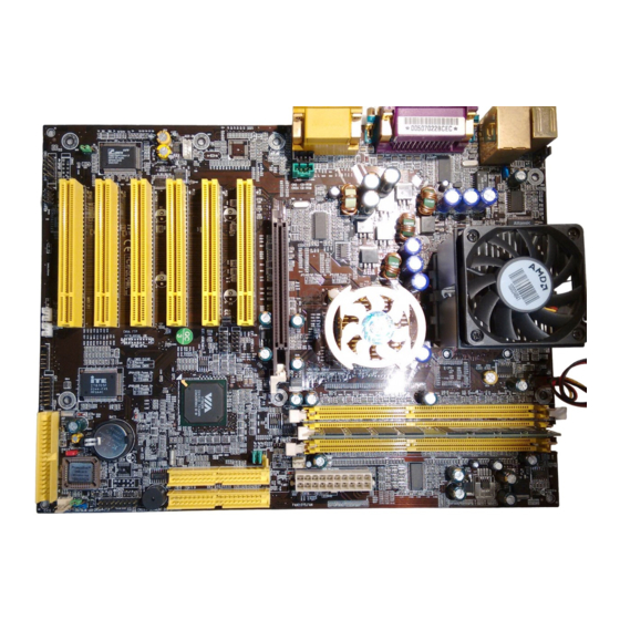
Page 6: Mainboard Layout
Introduction 1-3 Mainboard Layout CN4C CN2,CN2A JP5,JP6 JP6A/B CN24 CN4B CN5A CN23 CN23A FAN1 JP23 FAN3 FAN2 CN1A CN17 JP31,JP30,JP3 PS/2 Mouse RJ45 Printer Port Game Port COM2 Line-out Line-in MIC PS/2 Keyboard USB 0/1 COM1... -
Page 7: Connector And Jumper Reference Chart
Chapter 1 1-4 Connector and Jumper Reference Chart Jumper & Function Page Connector No. Clear CMOS Data External Clock Frequency PS/2 Keyboard Power-on Function JP6/JP6A/JP6B Power On By USB 0/1,2/3 and 4/5 On board Audio JP30 ROM SIP JP31 166MHz CPU Clock Over Ride Power Button Connector Power Indicator LED Connector System Reset Switch Connector... -
Page 8: Chapter 2 Hardware Setup
Hardware Setup Chapter 2 Hardware Setup If your mainboard has already been installed in your computer you may still need to refer to this chapter if you plan to upgrade your system's hardware. This mainboard is electrostatic sensitive. Do not thouch without wearing proper safety gudget and make sure to disconnect the power cable from the power source before performing any work on your mainboard . -
Page 9: Connector And Jumper Settings
Chapter 2 2-3 Connector and Jumper Settings Connectors are used to link the system board with other parts of the system, including the power supply, the keyboard, and the various controllers on the front panel of the system case. The power supply connector is the last connection to be made while installing a mainboard. -
Page 10: Over-Ride Power Button
Hardware Setup Front Panel Connector Set (CN1A) A through F A. Over-ride Power Button Connector The power button on the ATX chassis can be used as a G -B T N G -B T N normal power switch as well as a device to activate + H D -L E D H D -L E D Advanced Power Management Suspend mode. - Page 11 Chapter 2 Clear CMOS Data (JP1) To clear the contents of the CMOS, please follow the steps Definition below. Normal (default) 1. Disconnect the system power supply from the power source. Clear CMOS Data 2. Set the jumper cap at location 2~3 for 5 seconds, then set it back to the default position.
-
Page 12: Wake Up On Lan
Hardware Setup 166MHz CPU Clock (JP31) This jumper allows user to configure the CPU clock speed at Definition 166MHz. by setting the jumper cup to pin 2-3. The External Clock JP3 Enable Frequency (JP3) will automatically disable. To enable JP3 function, 166MHz set the jumper cup to pin 1-2. - Page 13 Chapter 2 Smart Card Reader Connector (CN7) This connector must be connected to an optional Smart card reader. Sample of Smart Card Reader (Optional) Blue LED Connector(CN17) This feature work entirely the same as the power indicator LED, both shows the system's power status. The only difference is that this one is blue while the other is red LED.
-
Page 14: Main Memory Configuration
Hardware Setup 2-4 Main Memory Configuration The DDR SDRAM memory system consists three banks and can supports the memory size up to 1GB on each bank . If you only use one bank it does not matter which one you use and if you use two or more banks, it does not matter which bank you install first. -
Page 15: Chapter 3 Phoenix-Awardbios Setup Program
User's Manual Chapter 3 Phoenix-AwardBIOS Setup Program Phoenix-AwardBIOS ROM has a built-in setup program that allows users to modify the basic system configuration. This information is stored in CMOS RAM so that it can retain the setup information, even when the power is turned off. When you turn on or reboot the system, press the Delete key to enter the Phoenix- AwardBIOS setup program. -
Page 16: Standard Cmos Setup
Award BIOS Setup Program 3-1 Standard CMOS Setup The Standard CMOS Setup allows users to configure system components such as hard disk drive, floppy disk drive and video display as well as date, time and boot-up error signaling. This configuration menu should be changed when installing a mainboard for the first time, changing hardware in your system such as the HDD, FDD, video display, or when the CMOS data has been lost or contaminated. -
Page 17: Advanced Bios Features Setup
User's Manual 3-2 Advanced BIOS Features By choosing the Advanced BIOS Features option from the CMOS Setup Utility menu (Figure 3-1), the screen below is displayed. This sample screen contains the manufacturer's default values for the mainboard. Phoenix - AwardBIOS CMOS Setup Utility Advanced BIOS Features Item Help Virus Warning... - Page 18 Award BIOS Setup Program C. Boot Up Features After turning on the system, BIOS will perform a series of device initialization and diagnostic tests discussed below. Quick Power On Self Test (POST) Enable this function to reduce the amount of time required to run the POST (Power On Self Test).
- Page 19 User's Manual E. Security Option The Supervisor and/or User Password functions shown in Figure 3-1 must be set to take advantage of this function. See Section 3-11 for password setting information. When the Security Option is set to System, a password must be entered to boot the system or enter the BIOS setup program.
-
Page 20: Advanced Chipset Setup
Award BIOS Setup Program 3-3 Advanced Chipset Features By choosing the Advanced Chipset Features option from the CMOS Setup Utility menu (Figure 3-1), the screen below is displayed. This sample screen contains the manufacturer's default values for the mainboard. Phoenix - AwardBIOS CMOS Setup Utility Advanced Chipset Features Item Help DRAM Clock/Drive Control... - Page 21 User's Manual B. AGP & P2P Bridge Control AGP Aperture Size This function determines the amount of system memory that is given to the AGP card. Options range from 4MB to 128MB. This is a dynamic memory allotment in that the AGP card will only use the amount of memory that it needs. The remaining memory not in use will be available for the system to use.
-
Page 22: Integrated Peripherals
Award BIOS Setup Program 3-4 Integrated Peripherals This section provides information on setting peripheral devices. By choosing the Integrated Peripherals option from the CMOS Setup Utility menu (Figure 3-1), the screen below is displayed. This sample screen contains the manufacturer's default values for the mainboard. - Page 23 User's Manual VIA OnChip LAN This feature allows you to enable the OnChip LAN function. Onboard CMedia Audio This feature allows user to select 6 channels function, if they installed an optional 6ch Expansion kit on this mainboard. C. Super IO Device Onboard FDC Controller Select Enabled if your system has a floppy disk controller (FDC) installed on the system board and you wish to use it.
-
Page 24: Power Management Setup
Award BIOS Setup Program 3-5 Power Management Setup This section provides information on the Green PC power management functions. By choosing the Power Management Setup option from the CMOS Setup Utility menu (Figure 3-1), the screen below is displayed. This sample screen contains the manufacturer's default values for the mainboard Phoenix - AwardBIOS CMOS Setup Utility Power Management Setup... - Page 25 User's Manual C. Video Off Option This setting allow you to selects the power-saving modes during which the monitor goes blank. D. Video Off Method This function serves as both a screen saver and power saver for monitors. See the next function, Video Off After, for setting the video timer. Blank - BIOS will only blank the monitor's screen.
-
Page 26: Wake Up On Lan/Ring
Award BIOS Setup Program G. IRQ/Event Activity Detect PS2KB Wakeup Select When enabled, the system is able to be turned on by a PS2 keyboard hot key. USB Resume from S3 When enabled, the system is able to resume form S3 mode by a USB keyboard hot key or mouse click. -
Page 27: Pnp/Pci Configuration
User's Manual 3-6 PNP/PCI Configuration This section provides IRQ and DMA setting information. By choosing the PNP/PCI Configuration option from the CMOS Setup Utility menu (Figure 3-1), the screen below is displayed. This sample screen contains the manufacturer's default values for the mainboard. -
Page 28: Pc Health Status
Award BIOS Setup Program 3-7 PC Health Status By choosing the PC Health Status option from the CMOS Setup Utility menu (Figure 3-1), the screen below is displayed. This field shows you the current system temperature/ external voltages input and the current CPU FAN and System FAN operating speed. Phoenix - AwardBIOS CMOS Setup Utility PC Health Status Shutdown Temperature... -
Page 29: Load Fail-Safe Defaults
User's Manual 3-9 Load Fail-Safe Defaults Load Fail-Safe Defaults loads the default BIOS values directly from the CMOS Setup Utility menu (Figure3-1). If the stored record created by the setup program becomes corrupted and therefore unusable, these defaults will be loaded automatically when you turn on the computer. -
Page 30: Supervisor Password & User Password Setting
Award BIOS Setup Program 3-11 Supervisor Password & User Password Setting There are four different variables that control password settings. The first two are located under the Security Option function in BIOS Features Setup Menu (Figure 3- 1). When the Security Option function is set to Setup, a password is required to enter BIOS and change BIOS settings. -
Page 31: Appendix I Cmedia 8738 Audio Subsystem
User's Manual Appendix I CMedia 8738 Audio Subsystem (option) The CMedia 8738 offers a new generation PCI audio solution: it utilizes the state-of- ® the-art CRL 3D Audio technology (HRTF 3D positional audio), and supports ® ® ® ® Microsoft Direct Sound 3D and Aureal 's A3D... - Page 32 Installation 1. Connect the front pair speakers to the Line-out jack of the audio adapter, and then connect rear pair speakers to Line-in/Rear jack of the audio adapter. The original Line-in can be moved to Aux-in. 2. Install the audio driver and Audio Rack application software. 3.
-
Page 33: Appendix Ii Thiz Linux Desktop 6.0
4. Type "thiz" password and click on "Go" button to enter your Linux destop to configures your user/password, network, modem dailup configuration and etc... *Note: For the latest driver updates, you can download these new drivers at http://www.chaintech.thizlinux.com...
Need help?
Do you have a question about the 7VJL and is the answer not in the manual?
Questions and answers