Table of Contents
Advertisement
Quick Links
CHAINTECH
Declaration of Conformity
According to 47 CFR, Parts 2 and 15 of the FCC Rules
7NJL1
The following designated product:
AMD Socket A
EQUIPMENT: MAINBOARD
MODEL NO.: 7NJL1
NVIDIA nForce 2 SPP+ MCP
is a Class B digital device that complies with 47 CFR Parts 2 and 15 of the FCC
Rules. Operation is subject to the following two conditions:
ATX Motherboard
1. This device may not cause harmful interference.
2. This device must accept any interference received, including interference that
may cause undesired operation.
User's Guide
This declaration is given to the manufacturer:
CHAINTECH-EXCEL COMPUTER INC.
4427 Enterprise St. Fremont, CA 94538, U.S.A.
Version 2.0
http://www.chaintech-excel.com
Chaintech President: Simon Ho
Signature:
Advertisement
Table of Contents

Related Manuals for CHAINTECH 7NJL1


Summary of Contents for CHAINTECH 7NJL1
-
Page 1: Declaration Of Conformity
The following designated product: AMD Socket A EQUIPMENT: MAINBOARD MODEL NO.: 7NJL1 NVIDIA nForce 2 SPP+ MCP is a Class B digital device that complies with 47 CFR Parts 2 and 15 of the FCC Rules. Operation is subject to the following two conditions: ATX Motherboard 1. -
Page 2: Chapter 1 Introduction
1 . 2 P ................2 ACKAGE ONTENTS 1 . 3 7NJL1 M ............4 OTHERBOARD IAGRAM This equipment has been tested and found to comply with the limits for a Class B digital device, 1 . 4 7NJL1 M ............ -
Page 3: Table Of Contents
Contents DDR MEMORY TEST TABLE ..........63 CPU FSB=266MH DDR ................63 CPU FSB=333MH DDR ................65 NOTES ....................67 HOW TO CONTACT CHAINTECH ..... 68... -
Page 4: Chapter 1 Introduction
ITE 8712 LPC I/O with system monitors hardware. Thermal grease pack Two UARTs support serial ports and IR function (up to 115.2Kbps) for HPSIR and ASKIR. One SPP/ECP/EPP parallel port. One floppy disk drive connector supports up to 2.88MB. 7NJL1 User’s Guide 7NJL1 User’s Guide... - Page 5 Earphone ( ∅ 3.5mm) phone jack MIC – in ( IEEE-1394 Ext. port Note: The 7NJL1 excludes the IEEE-1394 function. If customers require the IEEE-1394 function, please purchase one IEEE-1394 card to expand the function. DigiDoc System Monitoring Display Green LED Display 2.
-
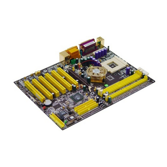
Page 6: Chapter 2 Hardware Setup
Chapter 1 Chapter 2 1.4 7NJL1 Motherboard Layout Chapter 2 Hardware Setup If your motherboard has already been installed in your computer you may still need to refer to this chapter if you plan to upgrade your system's hardware. This motherboard is electrostatic sensitive. Do not touch without wearing proper safety gadget and make sure to disconnect the power cable from the power source before performing any work on your motherboard. -
Page 7: Cpu J Umper C Onfiguration
Do not hit the components L47, L48 and C231 while installing your heat sink. 1.2G 1.2 GHz 12.0 1.6V 64KB 0.18 Inappropriate installation might damage the inductances and capacitance. 1.3G 1.3 GHz 13.0 1.6V 64KB 0.18 7NJL1 User’s Guide 7NJL1 User’s Guide... - Page 8 0.13 1400 14.0 1.75V 256KB 0.18 1400MHz 1000 1000MHz 1.75V 256KB 0.18 1113 1113MHz 1.75V 256KB 0.18 1200 1.75V 256KB 0.18 1200MHz 1333 1333MHz 10.0 1.75V 256KB 0.18 1400 10.5 1.75V 256KB 0.18 1400MHz 7NJL1 User’s Guide 7NJL1 User’s Guide...
-
Page 9: M Ain M Emory C Onfiguration
Chassis Open Alarm Connector Note: Smart Card Reader Connector For maximized Dual-channel (128-bit) result, you must install one of your two memory modules on DDR3. Memory compatibility test please refer to Appendix DDR Memory Test. 7NJL1 User’s Guide 7NJL1 User’s Guide... - Page 10 Green button on your ATX case, or enabling the Power Management and pay attention to the correct cables and pin orientation (i.e., not to reverse the Suspend Mode options in BIOS's Power Management menu. (See section 3.5) order of these two connectors.) 7NJL1 User’s Guide 7NJL1 User’s Guide...
- Page 11 3. Connect the system's power and then start the system. 4. Enter BIOS's CMOS Setup Utility and choose Load Setup Defaults. Type [Y] and press [enter]. 5. Set the system configuration in the Standard CMOS Setup menu. 7NJL1 User’s Guide 7NJL1 User’s Guide...
- Page 12 This connector is for AUX Audio Device. This function allows you to enable or disable the on board audio. You must set the jumper cap to pins 1-2 to enable or set pins 2-3 to disable this function. 7NJL1 User’s Guide 7NJL1 User’s Guide...
- Page 13 2-3 to use this function. board contains a USB Host controller and includes a root hub with two connector for optional USB Adaptor (USB 2/3 and 4/5). 7NJL1 User’s Guide 7NJL1 User’s Guide...
- Page 14 The wiring and plug may vary depending on the manufacturer. On standard This connector must be connected to an optional DigiDoc System Monitoring fans, the red is positive (+12V) and the black is ground. Display 7NJL1 User’s Guide 7NJL1 User’s Guide...
- Page 15 This header is used to connect an add-in NIC (Network to support IR function. (See section 3.4 Super I/O Device of Integrated Interface Card) which gives WOL capability to the motherboard. Peripherals) 7NJL1 User’s Guide 7NJL1 User’s Guide...
- Page 16 These features work entirely the same as the power indicator LED, both shows This connector must be connected to an optional Smart card reader. the system’s power status. The only difference is that this one is blue while the other is red LED. 7NJL1 User’s Guide 7NJL1 User’s Guide...
-
Page 17: Chapter 3 Bios Setup Program
80 Port Display CN25 Note: The 7NJL1 excludes IEEE 1394 function. If customers require IEEE 1394 function, please purchase one IEEE 1394 card to expand the function. * Remove CN24 Jumper Caps on motherboard 5-6, 9-10 before installation. -
Page 18: A Dvanced Bios F Eatures
Cache memory is much faster than conventional DRAM system memory. These fields allow you to enable or disable the CPUs Level 1 built-in cache and Level 2 external cache. Both settings are left enabled to significantly increase the performance of your computer. 7NJL1 User’s Guide 7NJL1 User’s Guide... - Page 19 The typematic rate sets the rate at which characters on the screen repeat when a key is pressed and held down. Typematic Delay (Msec) The typematic delay sets how long after you press a key that a character begins repeating. 7NJL1 User’s Guide 7NJL1 User’s Guide...
-
Page 20: A Dvanced C Hipset F Eatures
(3) CPU Ratio: Selecting [Enabled] to allow Fast Write Protocol for 8x/4x AGP to function. It is recommended to keep the default setting for stable system operation. Not all AGP cards support fast write. 7NJL1 User’s Guide 7NJL1 User’s Guide... -
Page 21: I Ntegrated P Eripherals
6ch Expansion kit to motherboard. MAC LAN (nVIDIA): (1) IDE Function Setup: This item allows you to Auto / Disabled the onboard LAN function. Press [Enter] to enter the sub-menu, which contains the following items for advanced control: 7NJL1 User’s Guide 7NJL1 User’s Guide... - Page 22 This item specifies an IRQ for the Midi port. S1 (POS): The S1 state is low power state. In this state, no system context (CPU or Chipset) is lost and the hardware maintains all system contexts. 7NJL1 User’s Guide 7NJL1 User’s Guide...
- Page 23 Settings: [Ctrl-F1] through [Ctrl-F12]. system in Suspend, a power saving mode. When set to Instant-Off the Soft-Off by PWR-BTN function is disabled and the computer turns completely off when the power button is pressed. 7NJL1 User’s Guide 7NJL1 User’s Guide...
-
Page 24: Pnp/Pci Configuration
Available options are [85°C/185°F], [90°C/194°F], [95°C/203°F], and Bit 5 of the command register in the PCI device configuration space is the VGA [100°C/210°F]. Palette Snoop bit (0 is disabled). Available options are [Enabled] and [Disabled]. 7NJL1 User’s Guide 7NJL1 User’s Guide... -
Page 25: Frequency/Voltage Control
BIOS settings. setting, while doing overclocking. Any attempt to operate beyond product specifications is not recommended. We do not guarantee the damages or risks caused by inadequate operation or beyond product specifications. 7NJL1 User’s Guide 7NJL1 User’s Guide... -
Page 26: Chapter 4 Driver Setup
Selecting this option and pressing Y followed by the [Enter] key lets you exit the Setup program without recording any new values or changing old ones. Figure 4-1 4.1 Nvidia Driver Package Setup 1. Please, select [Nvidia Driver Package] 2. Please, select [NEXT] 7NJL1 User’s Guide 7NJL1 User’s Guide... - Page 27 Chapter 4 Chapter 4 3. Please, select [ YES ] 5. Please, select [Yes] 6. Please, select [Continue Anyway] 4. Please, select [ Next ] 7. Please, select [Continue Anyway] 7NJL1 User’s Guide 7NJL1 User’s Guide...
- Page 28 4.2 USB 2.0 Driver Setup This section provides information on installed audio devices by choosing [USB 2.0 Driver] from the Setup Driver menu. (Figure 4 - 1) Note: USB 2.0 only support Windows 2000 / XP operation system. 7NJL1 User’s Guide 7NJL1 User’s Guide...
- Page 29 6. Please select [ Next ] 4. Please select [ Next ] 7. Please wait; select [ OK ], after restart. 5. Please select [ Next ] 8. Select different channels according to you speakers 7NJL1 User’s Guide 7NJL1 User’s Guide...
-
Page 30: Chapter 5 Audio Device Application
You can start the Audio Rack by selecting 【Start】 → 【Program】 → 【PCI Audio C. [ Help ] Applications】→【Audio Rack】 CD Player Output Configuration MIDI Player Output Configuration MP3 Wave Player Configuration Mixer Setup 7NJL1 User’s Guide 7NJL1 User’s Guide... - Page 31 User 4ch XeaR mode setup (1) Speakers: • Headset & 2 channel speaker setup • User 6ch XeaR mode setup • 4 channel speaker setup (2) Volume: • 6 channel speaker setup (3) Sound Effect: 7NJL1 User’s Guide 7NJL1 User’s Guide...
- Page 32 C. Under Windows 2000 / ME / XP Setup: 3 options available for Output device: [MidiOut Device], [Microsoft GS Wavetable SW Synth], [Roland MPU-401] (1) Enable to choose the Audio CD drive of your system. 7NJL1 User’s Guide 7NJL1 User’s Guide...
- Page 33 This is to setup the high and low pitch of the sound frequency output. (3) Surround: This is for setting up speaker output mode. (4) Playback Mode To select the music playback mode provided. Configuration: 7NJL1 User’s Guide 7NJL1 User’s Guide...
-
Page 34: Multi- Channel Demo
Click on the wide-screen TV in the center to get into [Advance] screen Set speaker function for demo mode: Set EAX function for demo mode: In Advance mode, here you can configure according to your system hardware or personal preference. 7NJL1 User’s Guide 7NJL1 User’s Guide... -
Page 35: Ddr Memory Test Table
512MB KVR333 Kingston W942508AH-6 TwinMOS 256MB PC-3200 TWINMOS Samsung TMD7608F8E50B 256MB PC333 Transcend K4H560838D-TCB3 NANYA 128MB DDR266 (CL:2) NT5DS16M8AT-7K Hyundai 256MB PC-2100(CL2.5) Hynix HY5DU28822AT-H Micron 128MB DDR266 (CL:2) Micron MT 46V16M8-75A Nanya 256MB PC-2100 NT5DS16M8AT-7K 7NJL1 User’s Guide 7NJL1 User’s Guide... -
Page 36: Cpu Fsb=333Mh Zddr
512MB PC3200 AData 256MB PC-3200 TWINMOS W942508BH-5 TMD7608F8E50B Winbond NANYA 512MB KVR333 Kingston 128MB DDR266 (CL:2) W942508AH-6 NT5DS16M8AT-7K Samsung Hyundai 256MB PC333 Transcend 256MB PC-2100(CL2.5) Hynix K4H560838D-TCB3 HY5DU28822AT-H Micron 128MB DDR266 (CL:2) Micron MT 46V16M8-75A 7NJL1 User’s Guide 7NJL1 User’s Guide... -
Page 37: Notes
403, Building A, No.118, Zhichun Rd, E-Mail: phil@chaintech.nl Haidian District, Beijing, China 100086 Tel: +86-10-6265-1626 For The Netherlands: Fax: +86-10-6262-0267 CHAINTECH reserves all the rights to change this manual .All CHAINTECH EUROPE B.V. URL: http://www.chaintech.com.cn Coenecoop 620 2741 PV WADDINXVEEN, E-MAIL: chaintech@21cn.com information is subject to change without notice.
Need help?
Do you have a question about the 7NJL1 and is the answer not in the manual?
Questions and answers