Table of Contents
Advertisement
Quick Links
CHAINTECH
7NJS
AMD Socket A
NVIDIA nForce 2 SPP+ MCP-T
ATX Motherboard
User's Guide
Version 3.0
Declaration of Conformity
According to 47 CFR, Parts 2 and 15 of the FCC Rules
The following designated product:
EQUIPMENT: MAINBOARD
MODEL NO.: 7NJS
is a Class B digital device that complies with 47 CFR Parts 2 and 15 of the FCC
Rules. Operation is subject to the following two conditions:
1. This device may not cause harmful interference.
2. This device must accept any interference received, including interference that
may cause undesired operation.
This declaration is given to the manufacturer:
CHAINTECH-EXCEL COMPUTER INC.
4427 Enterprise St. Fremont, CA 94538, U.S.A.
http://www.chaintech-excel.com
Chaintech President: Simon Ho
Signature:
Advertisement
Table of Contents

Related Manuals for CHAINTECH CT-7NJS


Summary of Contents for CHAINTECH CT-7NJS
- Page 1 2. This device must accept any interference received, including interference that User's Guide may cause undesired operation. This declaration is given to the manufacturer: CHAINTECH-EXCEL COMPUTER INC. 4427 Enterprise St. Fremont, CA 94538, U.S.A. Version 3.0 http://www.chaintech-excel.com Chaintech President: Simon Ho Signature:...
- Page 2 Contents Federal Communications Commission Statement This device complies with FCC Rules Part 15. Operation is subject to the following two conditions: CHAPTER 1 INTRODUCTION ........... 1 * This device may not cause harmful interference. 1 . 1 P ..............1 RODUCT PECIFICATIONS * This device must accept any interference received, including interference that may cause undesired...
-
Page 3: Table Of Contents
UTOMATICALLY ..............82 IEWING RIVE SSIGNMENTS .................. 83 ELETING RRAY ............. 85 EBUILDING IRRORED RRAY DDR MEMORY TEST TABLE ..........87 CPU FSB=266MH DDR ................87 CPU FSB=333MH DDR ................89 NOTES ..................91 HOW TO CONTACT CHAINTECH ..... 92... - Page 4 Chapter 1 Chapter 1 On board Super I/O Controller Chapter 1 Introduction ITE 8712 LPC I/O with system monitors hardware. Two UARTs support serial ports and IR function (up to 115.2Kbps) for 1.1 Product Specifications HPSIR and ASKIR. Processor One SPP/ECP/EPP parallel port. Supports AMD Socket A Duron/Athlon/Athlon XP CPU One floppy disk drive connector supports up to 2.88MB.
- Page 5 10. CD Box Include: Driver CD Value-pack 2003 11. Thermal grease pack Special Features: 1. CBOX™2, Chaintech’s exclusive front panel. Include: USB (1.1 / 2.0 compliant) Ext. ports ∅ 3 . 5 m m ) Earphone ( phone jack ∅ 3 . 5 m m ) MIC –...
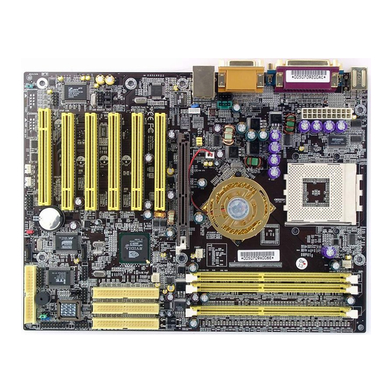
- Page 6 Chapter 1 Chapter 2 1.4 7NJS Motherboard Layout Chapter 2 Hardware Setup If your motherboard has already been installed in your computer you may still need to refer to this chapter if you plan to upgrade your system's hardware. This motherboard is electrostatic sensitive. Do not touch without wearing proper safety gadget and make sure to disconnect the power cable from the power source before performing any work on your motherboard.
- Page 7 Chapter 2 Chapter 2 2.2 CPU Jumper Configuration Frequency Configuration: If you install a CPU on this motherboard, you must set the [External Clock Frequency] JP25 according to your processor (See Section 2.4). * CPU Speed = Multiplier x FSB Frequency You do not need to make voltage settings because this board will automatically set your CPU voltage.
- Page 8 Chapter 2 Chapter 2 AMD Athlon CPU (K7/Thunderbird) 2.3 Main Memory Configuration Micron The DDR SDRAM memory system consists three banks, each bank supports Model Multiplier Vcore Speed Frequency Cache process up to 1GB of memory. 700MHz 1.70V 256KB 0.18 1.70V 256KB 0.18...
- Page 9 Chapter 2 Chapter 2 2.4 Connector and Jumper Reference Chart 2.5 Connector and Jumper Settings Connectors are used to link the system board with other parts of the system, Jump Connector Function Page including the power supply, the keyboard, and the various controllers on the ATX Power Supply Connector front panel of the system case.
- Page 10 Chapter 2 Chapter 2 Poly-fuse Over Current Protection: B. P-LED (Power LED Connector): The poly-fuse protects the system from dangerous voltages that the system The power indicator LED shows the system's power status. It is important to might be exposed to via the keyboard or USB connector. In case of such pay attention to the correct cables and pin orientation (i.e., not to reverse the exposure, the poly-fuse will immediately be disconnected from the circuit, just order of these two connectors.)
-
Page 11: Ide 1 / 2 Ide Hard-Disk Connector
Chapter 2 Chapter 2 IDE 1/2 (IDE Hard-Disk Connector) J1 /J2 (Serial ATA Connector): This can connect to new IDE device, it support ATA 150MB/sec. This connector is used for connecting 40 pins of ATAPI devices. Notes: Setup problem, please refer to Appendix Serial ATA/IDE RAID IDE 1 only connects two IDE devices. -
Page 12: Jp25 Setup Cpu Fsb. Freq. Jumper
Chapter 2 Chapter 2 JP25 (Setup CPU FSB Freq.): CN2/CN2A (CD-ROM Audio-in Connector): Definition 133/166 MHz (default) 100 MHz This cap setups up the CPU Ext. Clock Frequency. Use the audio cable enclosed with your CD-ROM disk drive to connect the 1-2: The default value is 133/166 MHz (The will allow the CPU’s Ext. -
Page 13: Cn4C Spdif Kit Connector
Chapter 2 Chapter 2 CN4B (AC3 Center / Surround + Bass Connector): JP6 (Power On By USB 0/1) Definition Disable (default) Enable A USB keyboard hot key or a USB mouse click can turn on this board. You This connector must be connected to a 6-channel bracket. must also set this jumper's cap to pins 2-3 to use this function. - Page 14 CN25 (DigiDoc System Monitoring Display): If you want to use a USB Keyboard, you must enable the USB keyboard CBOX2 features CHAINTECH’s exclusive [DigiDoc], the most advance support function in BIOS's Integrated Peripherals menu (See Section 3.4). This system diagnostic monitoring display.
-
Page 15: Fan4 North Bridge Cooling Fan Power Connector (12V)
Chapter 2 Chapter 2 FAN4 (North Bridge Cooling Fan Power) CN5 [WOL (Wake-on-LAN) Connector]: The north bridge-cooling fan. The wiring and plug may vary depending on the Enable the Power ON by Ring selection in BIOS's Power Management Menu manufacturer. On standard fans, the red is positive (+12V), the black is ground. to use this function. -
Page 16: Jp23 Green Led Mode Jumper
LED. CN9 (Chassis Open Alarm Connector): JP23 (Green Mode LED): Definition CHAINTECH (default) This connector provides a buzzer sound when an attempt to open the chassis This cap is to setup Green LED flash mode. (Optional) occurs. - Page 17 Chapter 2 Chapter 2 CN7 (Smart Card Reader Connector): 2.6 1394 ACR Card CBOX-2 Connector This connector must be connected to an optional Smart card reader. Regulations for standard PnP PCI2.1 and IEEE1394a interface. The transmission speed so far for IEEE1394 is 100/ 200/ 400Mbps. In the future the maximum transmission speed will reach 800Mbps or even 1Gbps.
- Page 18 Chapter 2 Chapter 3 2.7 CBOX™ 2 Setup Chapter 3 BIOS Setup Program Gently insert CBOX™ 2 into the regular 5-1/4” drive bay at the front Phoenix-Award BIOS ROM has a built-in setup program that allows users to of system chassis and securely tighten the side screws. modify the basic system configuration.
- Page 19 Chapter 3 Chapter 3 3.1 Standard CMOS Setup Halt On: When the system is powered on, BIOS performs a series of diagnostic tests The Standard CMOS Setup allows users to configure system components called POST (Power On Self Test). This function stops the computer if BIOS such as hard disk drive, floppy disk drive and video display as well as date, time detects a hardware error.
- Page 20 Chapter 3 Chapter 3 (3) Quick Power On Self Test (POST): information. When the Security Option is set to System, a password must be Enable this function to reduce the amount of time required to run the POST entered to boot the system or enter the BIOS setup program. When the Security (Power On Self Test).
- Page 21 Chapter 3 Chapter 3 3.3 Advanced Chipset Features (4) CPU Interface: Optimal: Select this option will let the system automatically detect its By choosing the [Advanced Chipset Features] option from the CMOS performance. Setup Utility menu (Figure 3-1), the screen below is displayed. This sample Aggressive: Select this option for better system performance.
- Page 22 Chapter 3 Chapter 3 (11) System BIOS Cacheable: On Chip IDE channel 0/1: Enabling this function allows caching of the system BIOS ROM at You can set this to disable the On Chip IDE controller if you are going to F0000h-FFFFFh, resulting in better system performance.
- Page 23 Chapter 3 Chapter 3 (3) Super IO Device: to initialize Display first. This section provides information on setting Super I/O device. By choosing (5) On Chip USB: the Integrated Peripherals option from the CMOS Setup Utility menu (Figure Enable the on-board Universal Serial Bus (USB V1.1 or V2.0) controller if 3-5), the screen below is displayed.
- Page 24 Chapter 3 Chapter 3 S1 (POS): the power button is pressed. The S1 state is low power state. In this state, no system context (CPU or (7) PwROn After PwR-Fail: Chipset) is lost and the hardware maintains all system contexts. This allows you to set whether you want your system to reboot after the S3 (STR): power has been interrupted.
- Page 25 Chapter 3 Chapter 3 3.6 PNP/PCI Configurations Slot 1,5/2/3/4 Use IRQ No: These Field automatically assign the IRQ for each PCI slot. The default setting This section provides IRQ and DMA setting information. By choosing the for each field is [Auto], which utilizes auto-routing to determine IRQ PNP/PCI Configuration option from the CMOS Setup Utility menu (Figure 3-1), assignments.
- Page 26 Chapter 3 Chapter 3 3.8 Frequency/Voltage Control 3.9 Load Fail-Safe Defaults By choosing the Frequency/Voltage Control option from the CMOS Setup Load Fail-Safe Defaults loads the default BIOS values directly from the Utility menu (Figure 3-1), the screen below is displayed. This sample screen CMOS Setup Utility menu (Figure3-1).
- Page 27 Chapter 3 Chapter 4 3.12 Save and Exit Setup Chapter 4 DRIVER Setup If you select this and type [Y] (for Yes) followed by the [Enter] key, the Please, insert nVidia Serial CD to CDROM. values entered in the setup utilities will be recorded in the CMOS memory of the BIOS chip.
- Page 28 Chapter 4 Chapter 4 3. Please, select [ YES ] 5. Please, select [Yes] 6. Please, select [Continue Anyway] 4. Please, select [ Next ] 7. Please, select [Continue Anyway] 7NJS User’s Guide 7NJS User’s Guide...
- Page 29 Chapter 4 Chapter 4 8. Please, select [Continue Anyway] 4.2 Promise Fast-Trak Driver This section provides information on installed audio devices by choosing [Promise Fast-Trak Driver] from the Setup Driver menu. (Figure 4 - 1) Using the Windows Add New Hardware function: 1.
- Page 30 Chapter 4 Chapter 4 • 3. Please select [ OK ] It should select CDROM:\NVUsb2.0\WinXP the USB2X.inf and then install the system files. • The host controller should be installed correctly when Device Manager is updated after the install. 4.4 C-MEDIA Sound Driver Setup This section provides information on installed audio devices by choosing [ Audio Drivers ] from the Setup Driver menu.
- Page 31 Chapter 4 Chapter 5 6. Please select [ Next ] Chapter 5 Audio Device Application This sound card supports Windows 95/98/ME/NT4.0/2000 operating systems. To start the Audio Application Program simply select the [Start]→[Program Files]→[PCI Audio Applications]→[Audio Rack] It includes the following options: (1) Audio Rack: Which includes Audio Rack, CD Player, MIDI Player, Mixer and MP3 Player.
- Page 32 Chapter 5 Chapter 5 1. C-Media Mixer Volume M i x e r A d v a n c e S e t t i n g : A. Volume Control (1) SPDIF: You can simply double click the icon located at button right corner of •...
- Page 33 Chapter 5 Chapter 5 • Format: User 4ch XeaR mode setup Select between Normal and Reverse. Device: For device feature select between S/PDIF #1 and S/PDIF #2. • Copyright Protection: Audio files have copyrights. Please select this option to prevent (2) Speakers: •...
- Page 34 Chapter 5 Chapter 5 (5) Option: [Help] 【Enable Hot-Key Setting】 This provides settings for Hot-Keys for Volume control, Mute, and Display. 【Enable Microphone Booster】 Enable the microphone’s electrical circuit to increases the sensitivity of the microphone. When designing the audio chip, it limits the type of microphones that are available.
- Page 35 Chapter 5 Chapter 5 [Help] : Configuration : Playback: Playback delay time for Mini-Disk recording. Please use default setting. Recording Configuration: Recording Format : Quality: (1) Name: This is to setup the recording format. There are 3 selections: CD Quality, Radio Quality, and Telephone Quality.
-
Page 36: Chapter 6 Digidoc
5.2 Multi- Channel Demo Chapter 6 DigiDoc STAR ] → [ Program ] → [ PCI Audio Applications ] → CBOX2 features CHAINTECH’s exclusive “DigiDoc”, the most advance [ Multi-Channel Demo ] system diagnostic monitoring display. 80-PORT diagnostic display during POST at system boot up! -
Page 37: Appendix
Digidoc 80-Port POST Error Code List Digidoc 80-Port POST Error Code List Appendix Digidoc 80-Port POST Error Code List POST (hex) Description Program chipset default values into chipset. Chipset POST (hex) Description default values are MODBINable by OEM customers. Test CMOS R/W functionality. Initial Early_Init_Onboard_Generator switch. - Page 38 Digidoc 80-Port POST Error Code List Digidoc 80-Port POST Error Code List POST (hex) Description POST (hex) Description 1. Initialize multi-language. Okay to enter Setup utility; i.e. not until this POST stage 2. Put information on screen display, including Award title, can users enter the CMOS setup utility.
-
Page 39: Serial Ata/Ide Raid
Digidoc 80-Port POST Error Code List Serial ATA/IDE RAID Serial ATA/IDE RAID Introduction POST (hex) Description What is the FastTrak 376 RAID controller? 1. USB final Initialization. Promise designed its FastTrak 376 to provide a cost-effective, high 2. NET PC: Build SYSID structure. performance RAID solution that adds performance and/or reliability to PC 3. -
Page 40: Steps For Installing Your Serial Ata/Ide Raid
Serial ATA/IDE RAID Serial ATA/IDE RAID will continue to function. This is called Fault Tolerance. If one drive has a Step 2: Installing the Hard Drives physical sector error, the mirrored drive will continue to function. If you wish to include your current bootable Serial or Parallel ATA drive using the Windows NT 4.x, Windows 2000, or Windows XP operating system on your With striping, identical drives can read and write data in parallel to increase FastTrak 376 Controller. - Page 41 Serial ATA/IDE RAID Serial ATA/IDE RAID Creating an Array for Performance FastTrak 376 (tm) BIOS Version 1.00.0.XX NOTE: (c) 2002-2005 Promise Technology, Inc. All Rights Reserved. FastTrak 376 allows users to create striped arrays with 1, 2 drives. No array defined . . . To create an array for best performance, follow these steps: Press <Ctrl-F>...
-
Page 42: Step 4: Installing Software Drivers
Serial ATA/IDE RAID Serial ATA/IDE RAID NOTE: 5) Press Enter key to Save selection and start duplication. The following progress FastTrak 376 permits only two drives to be used for a single Mirrored array in Auto screen will appear. Setup. Start to duplicate the image . -
Page 43: Using Fastbuild™ Configuration Utility
Serial ATA/IDE RAID Serial ATA/IDE RAID 6. The Windows 2000 Setup screen will appear again saying [Setup will load Using FastBuild™ Configuration Utility support for the following mass storage devices:] The list will include The FastBuild™ Configuration Utility offers several menu choices to create and [Win2000 Promise FastTrak 376 (tm) controller]. -
Page 44: Navigating The Fastbuild™ Setup Menu
Serial ATA/IDE RAID Serial ATA/IDE RAID Navigating the FastBuild™ Setup Menu you are creating. After making all selections, use Ctrl-Y to save selections. FastBuild™ will automatically build the array. When using the menus, these are some of the basic navigation tips: Arrow keys highlights through choices;... -
Page 45: Assignments
Serial ATA/IDE RAID Serial ATA/IDE RAID U4 refers to 66MB/sec transfers, etc.) FastBuild (tm) Utility 2.xx (c) 2002-2005 Promise Technology, Inc. [ Delete Array Menu ] FastBuild (tm) Utility 1.xx (c) 1995-2000 Promise Technology, Inc. Array No RAID Mode Total Drv Capacity(MB) Status [ View Drive Assignments ]... -
Page 46: Rebuildinga Mirrored Array
Serial ATA/IDE RAID Serial ATA/IDE RAID Rebuilding A Mirrored Array FastBuild (tm) Utility 2.xx (c) 2002-2005 Promise Technology, Inc. The Rebuild Array [5] Menu option is necessary to recover from an error in a mirrored disk array. You will receive an error message when booting your [ Rebuild Array Menu ] system from the FastTrak BIOS. -
Page 47: Ddr Memory Test Table
DDR Memory TEST Table DDR Memory TEST Table DDR Memory TEST Table P r o d u ct V e n d o r C o m p o n e n t CPU FSB=266MHz DDR N a m e Samsung Memory List 128MB PC-2100 (CL:2.5) -
Page 48: Cpu Fsb=333Mh Zddr
DDR Memory TEST Table DDR Memory TEST Table CPU FSB=333MHz DDR Memory List P r o d u ct N a m e V e n d o r C o m p on e n t Nanya P r o d u ct N a m e V e n d o r C o m p on e n t 256MB PC-2100... -
Page 49: Notes
Haidian District, Beijing, China 100086 Tel: +86-10-6265-1626 For The Netherlands: Fax: +86-10-6262-0267 CHAINTECH reserves all the rights to change this manual. CHAINTECH EUROPE B.V. URL: http://www.chaintech.com.cn All information is subject to change without notice.
Need help?
Do you have a question about the CT-7NJS and is the answer not in the manual?
Questions and answers