Table of Contents
Advertisement
Declaration of Conformity
7VJS
According to 47 CFR, Parts 2 and 15 of the FCC Rules
The following designated product:
AMD Socket A
EQUIPMENT: MAINBOARD
VIA KT400 + VT8235
MODEL NO.: CT-7VJS
ATX Motherboard
is a Class B digital device that complies with 47 CFR Parts 2 and 15 of the FCC
Rules. Operation is subject to the following two conditions:
User's Guide
1. This device may not cause harmful interference.
2. This device must accept any interference received, including interference that
may cause undesired operation.
This declaration is given to the manufacturer:
CHAINTECH-EXCEL COMPUTER INC.
4427 Enterprise St. Fremont, CA 94538, U.S.A.
Version 2.0
http://www.chaintechusa.com
Chaintech President: Simon Ho
Signature:
Advertisement
Table of Contents

Related Manuals for CHAINTECH 7VJS


Summary of Contents for CHAINTECH 7VJS
-
Page 1: Declaration Of Conformity
AMD Socket A EQUIPMENT: MAINBOARD VIA KT400 + VT8235 MODEL NO.: CT-7VJS ATX Motherboard is a Class B digital device that complies with 47 CFR Parts 2 and 15 of the FCC Rules. Operation is subject to the following two conditions: User’s Guide... -
Page 2: Table Of Contents
This equipment has been tested and found to comply with the limits for a Class B digital device, pursuant to 1-3 7VJS Motherboard Diagram ................3 Part 15 of the FCC Rules. These limits are designed to provide reasonable protection against harmful interference in a 1-4 7VJS Motherboard Layout.................. -
Page 3: Chapter 1 Introduction
Chapter 1 Chapter 1 Boot-Block Flash ROM - Award system BIOS support PnP, APM, DMI, ACPI, & Multi-device. Introduction Chapter 1 1-1 Product Specifications Processor 1-2 Package Contents - Supports AMD Socket A Duron/Athlon/Athlon XP CPU This product comes with the following components: - System clock supports 200/266/333MHz Motherboard Chipset... -
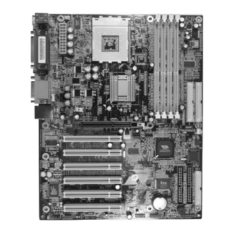
Page 4: 7Vjs Motherboard Diagram
Chapter 1 Chapter 1 1-3 7VJS Motherboard Diagram 1-4 7VJS Motherboard Layout... -
Page 5: Chapter 2 Hardware Setup
Chapter 2 Chapter 2 Hardware Setup longer necessary to make many jumper settings as on conventional motherboard. Chapter 2 After installing all your hardware into your PC system, you can manually configure your CPU clock according to your processor’s specifications. By turning on your If your motherboard has already been installed in your computer you may still need system’s power. -
Page 6: Connector And Jumper Settings
Chapter 2 Chapter 2 2-5 Connector and Jumper Settings CN1A (Front Panel Connector) A through F Connectors are used to link the system board with other parts of the system, including the power supply, the keyboard, and the various controllers on the front panel of the system case. - Page 7 Chapter 2 Chapter 2 FD1 (Floppy Disk Connector) JP1 (Clear CMOS Data) Definition Normal (default) 2-3 Clear CMOS Data To clear the contents of the CMOS, please follow the steps below. 1. Disconnect the system power supply from the power source. This connector is used to connect 34 pins of Floppy.
- Page 8 Chapter 2 Chapter 2 CN2/CN2A (CD-ROM Audio-in Connector): CN4B (AC3 Center / Surround + Bass Connector) This connector must be connected to a 6-channel bracket. (Optional) Use the audio cable enclosed with your CD-ROM disk drive to connect the CD-ROM to your motherboard. This will enable your CD-ROM's audio function. JP6 (Power On By USB 0/1) Definition Disable (default)
- Page 9 Chapter 2 Chapter 2 JP6A & JP6B (Power On By USB 2/3 and 4/5) CN24 (Front Panel Audio Connector) Definition Disable (default) Enable This connector give you the option of a front panel audio jack cable ext. to be plug JP6A USB 2/3, JP6B USB 4/5...
- Page 10 Chapter 2 Chapter 2 JP5 (Power On By Keyboard) CN5A [WOM (Wake-on-Modem) Connector] Definition Disable (default) Enable Enable the Power On by Ring selection in BIOS's Power Management Menu to use This board can be turned on by the PS / 2 keyboard (hot key). To use this function, this function.
- Page 11 Chapter 2 Chapter 2 JP23 (Green Mode LED) CN7 (Smart Card Reader Connector) Definition Default This connector must be connected to an optional Smart card reader. This cap is to setup Green LED flash mode. (Optional) JP3 (External Clock Frequency) CN17 (Blue LED Connector) Definition 1-2 100 MHz (default)
-
Page 12: Chapter 3 Bios Setup Program
Chapter 2 Chapter 3 JP31 (166MHz Clock Frequency) BIOS Setup Program Chapter 3 Phoenix-Award BIOS ROM has a built-in setup program that allows users to modify Definition the basic system configuration. This information is stored in CMOS RAM so that it JP3 Enable can retain the setup information, even when the power is turned off. -
Page 13: Advanced Bios Features
Chapter 3 Chapter 3 Date/Time These fields allow you to enable or disable the CPUs Level 1 built-in cache Set the date and time of the system. and Level 2 external cache. Both settings are left enabled to significantly IDE (Primary/Secondary; Master/Slave) increase the performance of your computer. -
Page 14: Advanced Chipset Features
Chapter 3 Chapter 3 are [1.4] and [1.1]. set to Manual, you can select the DRAM CAS Latency, Bank Interleave, (12) OS Select (For DRAM >64MB) Precharge to Active(Trp), Active to Precharge(Tras), Active to CMD(Trcd), If your system's DRAM is larger than 64MB and you are running OS/2, select DRAM Burst Length, DRAM Queue Depth, DRAM Command Rate, Write OS/2 as the item value. -
Page 15: Integrated Peripherals
Chapter 3 Chapter 3 Auto Configuration is enabled, you must set the DRAM timing function to 60ns or 70ns, provide successively increased performance. In Auto mode, the system automatically determines the best mode for each device. depending on the type of DRAM you install. 4. -
Page 16: Power Management Setup
Chapter 3 Chapter 3 [Disable], [201] and [209]. ACPI Suspend Type 9. Midi Port Address This feature allows user to select a suspend type for the operating system to turn off This item disables or assigns the address of the Midi port. Available options are peripherals devices, such as CD-ROM players, when they are not in use. -
Page 17: Pnp/Pci Configurations
Chapter 3 Chapter 3 options include [Auto], [On], [Off]. Reset Configuration Data If you want to reset CMOS IRQ divide hardware device, please selected to [Enabled]. IRQ/Event Activity Detect Resources Controlled By 1. PS2KB Wakeup Select When set to Manual the system BIOS will not refer to the ESCD for IRQ & DMA When enabled, the system can be turned on by a PS2 keyboard hot key. -
Page 18: Load Fail-Safe Defaults
Chapter 3 Chapter 3 3-10 Load Optimized Defaults Load Optimized Defaults loads the default system values directly from the CMOS Setup Utility menu (Figure3-1). If the stored record created by the setup program becomes corrupted and therefore unusable, these defaults will be loaded automatically when you turn on the computer. -
Page 19: Chapter 4 Driver Setup
Chapter 4 Chapter 4 DRIVER Setup Please select [YES] Chapter 4 Please, insert VIA Series CD to CDROM. Figure 4-1 4-1 VIA Service Pack Setup Please select [VIA Service Pack] Please select [Next >] Please select [NEXT >]... -
Page 20: Audio Driver Setup
Chapter 4 Chapter 4 Please select [Next >] Please select [Next >] Please select [OK] to finish setup. Please select [Next >] 4-2 Audio Driver Setup 1. Click [Audio Drivers]... - Page 21 Chapter 4 Chapter 4 2. Click [Install Device Driver and Applications] to start software installation 5. Please select [Next >] to continue. 6. Please select [Next >] to continue. 3. Please select the language to continue. 4. Please select [Next >] 7.
-
Page 22: Lan Driver Setup
Chapter 4 Chapter 4 4-3 LAN Driver Setup 4. Please select [Yes] to accept the license agreement. 1. Click [LAN Driver] 2. Please select [OK] to complete setup. 4-4 USB 2.0 Driver 1. Click [USB 2.0 Driver] 2. Click [Next >] to start software installation. 5. -
Page 23: Chapter 5 Audio Device Application
Chapter 4 Chapter 5 7. Please select [OK] to continue. Audio Device Application Chapter 5 This sound card supports Windows 95/98/ME/NT4.0/2000 operating systems. To start the Audio Application Program simply select the [Start]→[Program Files]→[PCI Audio Applications]→[Audio Rack] It includes the following options: (1) Audio Rack Which includes Audio Rack, CD Player, MIDI Player, Mixer and MP3 Player. - Page 24 Chapter 5 Chapter 5 SW Synth, A/V (AUX) In, MONO IN, and LINE IN. Mixer Recording Control This control panel includes CD Audio, Microphone, WAVE, Stereo Mix, A/V (AUX IN), and LINE IN. [ Help ] User 4ch XeaR mode setup •...
- Page 25 Chapter 5 Chapter 5 Setup: A. Under Win 95 / 98 3 options available for Output device: [Default MidiOut Device], [MPU-401], [Microsoft GS Wavetable SW Synth]. B. Under Windows NT4.0 Only CMPCI MIDI device is available. 【 Enable Hot Keys 】 C.
-
Page 26: Multi- Channel Demo
Chapter 5 Chapter 5 Playback delay time for Mini-Disk recording. Please use default setting. Set speaker function for demo mode Recording Configuration: Recording Format: Quality: (1) Name: This is to setup the recording format. There are 3 selections: CD Quality, Radio Quality, and Telephone Quality. - Page 27 NOTE How To Contact CHAINTECH How To Contact CHAINTECH Please do not hesitate to contact us if you have any problem about our products. Any opinion will be appreciated. NOTE For Asia, Africa, Australia and Pacific Island: For UK: CHAINTECH COMPUTER CO., LTD CHAINTECH UK., LTD.
Need help?
Do you have a question about the 7VJS and is the answer not in the manual?
Questions and answers