Table of Contents
Advertisement
AMD®
Motherboard
7NIL1
AMD® Socket A
NVIDIA nForce 2 SPP+ MCP
u-ATX Motherboard
User's Manual
Version 1.0
Declaration of Conformity
According to 47 CFR, Parts 2 and 15 of the FCC Rules
The following designated product:
EQUIPMENT: MAINBOARD
MODEL NO.: 7NIL1
is a Class B digital device that complies with 47 CFR Parts 2 and 15 of the FCC
Rules. Operation is subject to the following two conditions:
1. This device may not cause harmful interference.
2. This device must accept any interference received, including interference that
may cause undesired operation.
This declaration is given to the manufacturer:
CHAINTECH-EXCEL COMPUTER INC.
4427 Enterprise St. Fremont, CA 94538, U.S.A.
http://www.chaintech-excel.com
Chaintech President: Simon Ho
Signature:
Advertisement
Table of Contents

Subscribe to Our Youtube Channel
Related Manuals for CHAINTECH 7NIL1


Summary of Contents for CHAINTECH 7NIL1
- Page 1 According to 47 CFR, Parts 2 and 15 of the FCC Rules The following designated product: 7NIL1 EQUIPMENT: MAINBOARD MODEL NO.: 7NIL1 AMD® Socket A NVIDIA nForce 2 SPP+ MCP is a Class B digital device that complies with 47 CFR Parts 2 and 15 of the FCC Rules.
-
Page 2: Table Of Contents
1-3 7NIL1 Motherboard Diagram................3 in a residential installation. This equipment generates, uses, and can radiate radio frequency energy. If this 1-4 7NIL1 Motherboard Layout ................4 equipment is not installed and used in accordance with the manufacturer's instructions, it may cause harmful interference to radio communications. -
Page 3: Chapter 1 Introduction
Chapter 1 Chapter 1 One floppy disk drive connector supports up to 2.88MB. Chapter 1 Introduction Integrates smart card reader function and interface, to be qualified for meeting PC/SC standard. 1-1 Product Specifications Fast Ethernet/Home Networking Controller with MII Interface Processor Support 10/100Mb Fast Ethernet or 1/10Mb HomePNA 2.0 with External PHY. -
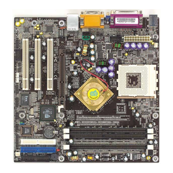
Page 4: 7Nil1 Motherboard Diagram
Chapter 1 Chapter 1 1-3 7NIL1 Motherboard Diagram 1-4 7NIL1 Motherboard Layout... -
Page 5: Chapter 2 Hardware Setup
Chapter 2 Chapter 2 2-2 Setting Your CPU’s Performance: Chapter 2 Hardware Setup Frequency Configuration: If your motherboard has already been installed in your computer you may still need If you install a CPU on this motherboard, you must set the [Front Side Bus to refer to this chapter if you plan to upgrade your system's hardware. -
Page 6: Main Memory Configuration
Chapter 2 Chapter 2 2-3 Main Memory Configuration AMD Athlon CPU (K7/Thunderbird) Micron This motherboards provides 3 184pin Double Data Rate (DDR) Dual Inline Memory Model CPU Speed Multiplier Vcore Modules (DIMM) slots. Which supports PC 1600/DDR200, PC2100/DDR266, Frequency Cache process PC2700/DDR333 and PC3200/DDR400 DDR SDRAM modules up to 3GB. -
Page 7: Connector And Jumper Reference Chart
Chapter 2 Chapter 2 2-4 Connector and Jumper Reference Chart 2-5 Connector and Jumper Settings Connectors are used to link the system board with other parts of the system, Jump Connector Function Page including the power supply, the keyboard, and the various controllers on the front panel of the system case. -
Page 8: Fd1 Floppy Connector
Chapter 2 Chapter 2 wakes up and can be remotely accessed. You may enable this function in BIOS's IDE 1/2 (IDE Hard-Disk Connector) Power Management Setup menu. (See section 3). Blinking LED in Suspend Mode: While in Suspend mode, the LED light on the front panel of your computer will flash. -
Page 9: Fan
Chapter 2 Chapter 2 JP5 (Keyboard Power On Function Jumper): FAN 4 (North Bridge Cooling Fan Power) Definition 1-2 Disable (default) Enable This board can be turned on by the PS / 2 keyboard (hot key). To use this function, The north bridge-cooling fan. -
Page 10: Jp6A /B Disable/Enable Usb 2/3,4/5 Device Power On Jumper
JP23 (Green LED Mode Jumper): CN1A (Front Panel Connector): Definition CHAINTECH (default) This motherboard provides a Green LED flash Jumper. This cap is to setup Green 1. PWR-SW (Over-ride Power Button Connector): LED flash mode. The default value is [1-2], which is manufacture defined. For user The power button on the ATX chassis can be used as a normal power switch as defend or OEM please set the jumper cap at [2-3]. -
Page 11: Cn2 /2A Cd-Rom Audio-In Connector
Chapter 2 Chapter 2 activities such as pressing a key on the keyboard or moving the mouse will bring CN3 (Auxiliary Audio-in Connector): the system back to Full-On. Pushing the button while in Full-On mode for more than [4 seconds] will switch the system completely off. See Over-ride Power Button Operation diagram. -
Page 12: Cn5 Wake On Lan Connector
Chapter 2 Chapter 2 CN5 [WOL (Wake-on-LAN) Connector]: CN7 (Smart Card Reader Connector): Enable the Wake Up On LAN selection in BIOS's Power Management Setup Menu to use this function. The capability to remotely manage PCs on a network is a This connector must be connected to a Smart card reader, which allows you to significant factor in reducing administrative and ownership costs. -
Page 13: Cn17 Blue Led Connector (5V)
Chapter 2 Chapter 2 CN17 (Blue LED Connector): CN24 (Front Audio Connector): These features work entirely the same as the power indicator LED, both shows the This connector give you the option of a front panel audio jack cable ext. to be plug system’s power status. -
Page 14: Chapter 3 Bios Setup Program
Chapter 2 Chapter 3 Chapter 3 BIOS Setup Program IR 2 (IR & CIR Connector): Phoenix-Award BIOS ROM has a built-in setup program that allows users to modify the basic system configuration. This information is stored in CMOS RAM so that it can retain the setup information, even when the power is turned off. -
Page 15: Standard Cmos Features
Chapter 3 Chapter 3 3-2 Advanced BIOS Features 3-1 Standard CMOS Features By choosing the Advanced BIOS Features option from the CMOS Setup Utility menu The Standard CMOS Features allows users to configure system components such as (Figure 3-1), the screen below is displayed. This sample screen contains the hard disk drive, floppy disk drive and video display as well as date, time and boot-up manufacturer's default values for the motherboard. - Page 16 Chapter 3 Chapter 3 Swap Floppy Drive APIC mode. Enabling APIC mode will expand available IRQs resources for the Enabling this function will swap the floppy drive assignment so that drive A will system. Available options are [Enabled] and [Disabled]. function as drive B, and drive B will function as drive A.
-
Page 17: Advanced Chipset Features
Chapter 3 Chapter 3 CPU Interface 3-3 Advanced Chipset Features This option allows you to determine how your CPU interface performs. Available By choosing the [Advanced Chipset Features] option from the CMOS Setup Utility options are: [Optimal] and [Aggressive] there details are as follows: menu (Figure 3-1), the screen below is displayed. -
Page 18: Integrated Peripherals
Chapter 3 Chapter 3 AGP Fast Write Capability 3-4 Integrated Peripherals Selecting [Enabled] to allow Fast Write Protocol for 8x/4x AGP to function. This section provides information on setting peripheral devices. By choosing the Not all AGP cards support fast write. Integrated Peripherals option from the CMOS Setup Utility menu (Figure 3-1), the screen below is displayed. - Page 19 Chapter 3 Chapter 3 5. IDE HDD Block Mode: modes. Block mode is also called block transfer, multiple commands, or multiple sector 6. ECP Mode Use DMA: read/write. If your IDE hard drive supports block mode, select Enabled to This item automatically specifies a DMA channel 1 or 3 for the parallel port when it auto-detect the optimal number of block read/writes per sector the drive can support.
-
Page 20: Power Management Setup
Chapter 3 Chapter 3 1. Blank Screen - BIOS will only blank the monitor's screen. The electricity saved in 3-5 Power Management Setup this mode is negligible and this function is only used as a screen saver to prevent This section provides information on the Green PC power management functions. By screen damage while the screen is on but not in use. -
Page 21: Pnp/Pci Configurations
Chapter 3 Chapter 3 signal and wake up the system from soft off and green mode. You should connect the 3-6 PNP/PCI Configurations modem to the COM port and call your PC to power on. This section provides IRQ and DMA setting information. By choosing the PNP/PCI 3. -
Page 22: Pc Health Status
Chapter 3 Chapter 3 3-7 PC Health Status 3-8 Frequency/Voltage Control By choosing the PC Health Status option from the CMOS Setup Utility menu (Figure By choosing the Frequency/Voltage Control option from the CMOS Setup Utility 3-1), the screen below is displayed. This field shows you the current CPU menu (Figure 3-1), the screen below is displayed. -
Page 23: Load Fail-Safe Defaults
Chapter 3 Chapter 3 3-9 Load Fail-Safe Defaults 3-12 Save and Exit Setup Load Fail-Safe Defaults loads the default BIOS values directly from the CMOS Setup If you select this and type [Y] (for Yes) followed by the [Enter] key, the values Utility menu (Figure3-1). -
Page 24: Chapter 4 Driver Setup
Chapter 4 Chapter 4 3. Please, click [OK] to continue. Chapter 4 DRIVER Setup Please insert the nVidia Serial driver CD into the CD-ROM. 4. Please click [NEXT>] to continue. 4-1 Nvidia Driver Package Setup 1. Please, select [Nvidia Driver Package] to begin installation. 2. -
Page 25: Audio Driver
Chapter 4 Chapter 4 6. Please, click [Continue Anyway] to continue install Nvidia Driver. 7. To restart you computer now, select [Yes, I want to restart my computer now.] then Please Click [OK] to restart you computer. If you do not want to restart your computer select [No, I will restart my computer later.] then click [OK] to 4-2 Audio driver continue. - Page 26 Chapter 4 Chapter 4 3. Please, click [Next>] to continue install the C-Media Audio driver. 5. Please, click [Next>] to continue install the C-Media Audio driver. 6. Please, click [Next>] to continue install the C-Media Audio driver. 4. Please, click [Next>] to continue install the C-Media Audio driver.
-
Page 27: Usb 2.0 Driver Setup
Chapter 4 Chapter 4 7. Please, click [Next>] to continue install the C-Media Audio driver. 9. To restart you computer now, select [Yes, I want to restart my computer now.] then Please Click [OK] to restart you computer. If you do not want to restart your computer select [No, I will restart my computer later.] then click [OK] to continue. -
Page 28: Chapter 5 How To Update Your Bios
Chapter 5 NOTE Chapter 5 How to update your BIOS? NOTE Embedded Flash Utility This motherboard is equipped with an Erasable Flash ROM and an Embedded Flash Utility, which allows the user to update the BIOS to a newer version. Embedded Flash All rights are reserved for the products and corporate names/logos that Utility eases BIOS upgrade and eliminate the compatibility issue etween different appear in this manual to their original owners.
Need help?
Do you have a question about the 7NIL1 and is the answer not in the manual?
Questions and answers