Table of Contents
Advertisement
Quick Links
MaxFit FE Series
Expandable Power Systems
Models Include:
MaxFit3FE
- 12VDC/24VDC @ 6A.
MaxFit5FE
- 12VDC @ 10A.
MaxFit7FE
- 24VDC @ 10A.
Installation Guide
Rev. MFEPS080119
Installing Company: _______________ Service Rep. Name: __________________________________
Address: _____________________________________________ Phone #: __________________
More than just power.
TM
Advertisement
Table of Contents

Subscribe to Our Youtube Channel
Related Manuals for Altronix MaxFit FE Series


Summary of Contents for Altronix MaxFit FE Series
- Page 1 MaxFit FE Series Expandable Power Systems Models Include: MaxFit3FE - 12VDC/24VDC @ 6A. MaxFit5FE - 12VDC @ 10A. MaxFit7FE - 24VDC @ 10A. Installation Guide Rev. MFEPS080119 More than just power. Installing Company: _______________ Service Rep. Name: __________________________________ Address: _____________________________________________ Phone #: __________________...
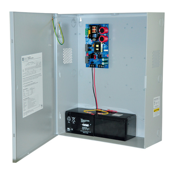
- Page 2 MaxFitFE Series Overview: Altronix MaxFit Expandable Power Systems provide system designers and installers with optimum power choices and the highest levels of versatility. They provide 12VDC or 24VDC via single output power supply/ charger. Includes AC fail, low battery, and battery presence monitoring. Enclosure accommodates up to four (4) 12VDC/12AH batteries.
- Page 3 4. Measure output voltage before connecting devices. This helps avoiding potential damage. 5. Connect devices or Altronix sub-assembly modules to be powered to the terminals marked [– DC +] (Fig. 1h, pg. 4). For auxiliary device connection, this output will not be affected by Low Power Disconnect or Fire Alarm Interface.
-
Page 4: Maintenance
Maintenance: Unit should be tested at least once a year for the proper operation as follows: Output Voltage Test: Under normal load conditions the DC output voltage should be checked for proper voltage level (MaxFitFE Configuration Chart, pg. 2). Battery Test: Under normal load conditions check that the battery is fully charged, check specified voltage at the battery terminals and at the board terminals marked [–... -
Page 5: Led Diagnostics
LED Diagnostics: Red (DC) Green (AC/AC1) Power Supply Status Normal operating condition. Loss of AC. Stand-by battery is supplying power. No DC output. Loss of AC. Discharged or no stand-by battery. No DC output. Red (Bat) Battery Status Normal operating condition. Battery fail/low battery. -
Page 6: Nec Power-Limited Wiring Requirements
NEC Power-Limited Wiring Requirements: Power-limited and non power-limited circuit wiring must remain separated in the cabinet. All power-limited circuit wiring must remain at least 0.25” away from any non power-limited circuit wiring. Furthermore, all power-limited circuit wiring and non power-limited circuit wiring must enter and exit the cabinet through different conduits. One such example of this is shown below. - Page 7 Notes: - 7 - MaxiFit3FE/MaxFit5FE/MaxFit7FE Expandable Power Systems Installation Guide...
- Page 8 1.25” (31.8mm) 1.25” (31.8mm) 7.00” (177.8mm) 7.00” (177.8mm) Altronix is not responsible for any typographical errors. –––––––––––––––––––––––––––––––––––––––––––––––––––––––––––––––––––––––––––––––––––––––––––––––––––––––––––––––– 140 58th Street, Brooklyn, New York 11220 USA | phone: 718-567-8181 | fax: 718-567-9056 website: www.altronix.com | e-mail: info@altronix.com | Lifetime Warranty MEMBER...
Need help?
Do you have a question about the MaxFit FE Series and is the answer not in the manual?
Questions and answers