
Subscribe to Our Youtube Channel
Related Manuals for SEW-Eurodrive MOVI-C CONTROLLER UHX65A


Summary of Contents for SEW-Eurodrive MOVI-C CONTROLLER UHX65A
- Page 1 *28514688_0219* Drive Technology \ Drive Automation \ System Integration \ Services Manual ® MOVI‑C CONTROLLER progressive UHX65A Edition 02/2019 28514688/EN...
- Page 2 SEW-EURODRIVE—Driving the world...
-
Page 3: Table Of Contents
Table of contents Table of contents General information........................ 6 About this documentation .................... 6 Structure of the safety notes ................... 6 1.2.1 Meaning of the signal words ................ 6 1.2.2 Structure of the section safety notes ............. 6 1.2.3 Structure of the embedded safety notes ............ 6 Decimal separator in numerical values ................ 7 Right to claim under warranty .................. 7 Other applicable documentation .................. 7... - Page 4 Table of contents Electrical installation ..................... 20 4.3.1 Shielding and routing bus cables .............. 20 4.3.2 Description of terminal functions .............. 21 4.3.3 Voltage supply.................... 22 4.3.4 Connection to Ethernet network.............. 22 4.3.5 Virtual network card (VNET) ................ 23 ® PLUS 4.3.6 EtherCAT /SBus...
- Page 5 Table of contents 10.3 Port overview ........................ 55 10.3.1 Interface description .................. 55 10.3.2 Engineering interface ................... 55 10.3.3 Windows interface .................. 55 Dimension drawings....................... 56 11.1 MOVI-C® CONTROLLER .................... 56 11.2 Accessories cable routing ..................... 57 Index ............................ 58 ® Manual – MOVI‑C CONTROLLER progressive UHX65A...
-
Page 6: General Information
General information About this documentation General information About this documentation The manual is part of the product and contains important information on operation and service. The manual is written for all employees who assemble, install, start up, and service the product. The manual must be accessible and legible. -
Page 7: Decimal Separator In Numerical Values
General information Decimal separator in numerical values – Measure(s) to prevent the hazard. Decimal separator in numerical values In this document, a period is used to indicate the decimal separator. Example: 30.5 kg Right to claim under warranty A requirement of fault-free operation and fulfillment of any rights to claim under limited warranty is that you adhere to the information in the documentation. -
Page 8: Safety Notes
Safety notes Preliminary information Safety notes Preliminary information The following general safety notes serve the purpose of preventing injury to persons and damage to property. They primarily apply to the use of products described in this documentation. If you use additional components, also observe the relevant warning and safety notes. -
Page 9: Target Group
Safety notes Target group Target group Specialist for me- Any mechanical work may only be performed by adequately qualified specialists. Spe- chanical work cialists in the context of this documentation are persons familiar with the design, me- chanical installation, troubleshooting, and maintenance of the product who possess the following qualifications: •... -
Page 10: Functional Safety Technology
Safety notes Functional safety technology Functional safety technology The product must not perform any safety functions without a higher-level safety sys- tem, unless explicitly allowed by the documentation. Transport Inspect the shipment for damage as soon as you receive the delivery. Inform the ship- ping company immediately about any damage. -
Page 11: Electrical Installation
Safety notes Electrical installation Electrical installation Ensure that all of the required covers are correctly attached after carrying out the elec- trical installation. Make sure that preventive measures and protection devices comply with the applic- able regulations (e.g. EN 60204-1 or EN 61800-5-1). 2.8.1 Required preventive measure Make sure that the product is correctly attached to the ground connection. -
Page 12: Introduction
Introduction General information Introduction General information 3.1.1 Content of this manual This manual describes: ® • The installation of the MOVI‑C CONTROLLER ® • The interfaces and LEDs of the MOVI-C CONTROLLER ® • The engineering access to the MOVI‑C CONTROLLER •... -
Page 13: Movi-C ® Controller
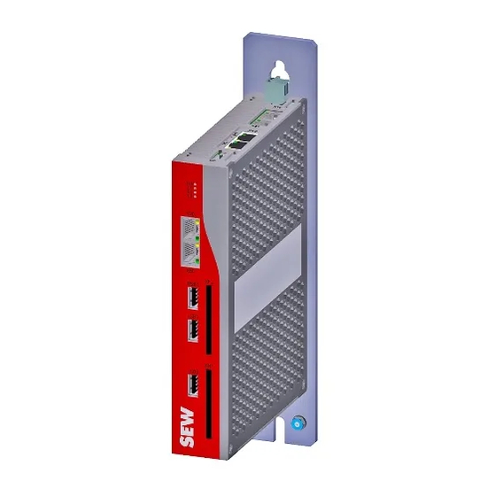
Introduction MOVI-C® CONTROLLER MOVI-C® CONTROLL ® MOVI-C CONTROLLER ® The MOVI-C CONTROLLER in the performance class "progressive" is a motion and logic controller for demanding automation tasks. The real-time operating system guar- antees very short response times as well as a high-performance connection of system buses from SEW‑EURODRIVE and standard fieldbuses. -
Page 14: Device Variants
Introduction MOVI-C® CONTROLLER 3.2.3 Device variants ® MOVI‑C CONTROLLER is available in the following device variants: Device variant Fieldbus interface ® UHX65A-0-04-N0 MOVI‑C CONTROLLER without a fieldbus interface and with E3845 CPU ® UHX65A-R-04-N0 MOVI‑C CONTROLLER with EtherNet/IP , Modbus TCP, and PROFINET IO CPU fieldbus interfaces and E3845 CPU ®... -
Page 15: Overview Of Communication Interfaces
Introduction MOVI-C® CONTROLLER 3.2.4 Overview of communication interfaces ® MOVI‑C CONTROLLER has the following communication interfaces: • The Ethernet communication interfaces allow for engineering purposes for the ® MOVI‑C CONTROLLER, for connecting an operator panel as well as for commu- nication with other Ethernet nodes (e.g. - Page 16 Introduction MOVI-C® CONTROLLER Ethernet communication interface (X90) The Ethernet communication interface(X90) is assigned to the Windows section of the ® MOVI‑C CONTROLLER. The interface is only available if the CFast memory card with Windows operating system is installed. The following functions can be realized via this interface: •...
-
Page 17: Omh Cfast Memory Cards
Introduction MOVI-C® CONTROLLER 3.2.5 OMH CFast memory cards The OMH CFast memory card (card for UHX65A: OMH65A-C1) is required for opera- ® tion of the MOVI‑C CONTROLLER and contains the firmware, the IEC program and user data (e.g. recipes). You can use the memory card for data backup and automatic parameterization in the event of an axis replacement. -
Page 18: Installation Notes
Installation notes Installation accessories Installation notes Installation accessories The following accessories can be ordered using the specific part number: 4.1.1 System bus cable ® Cable for connecting MOVI-C CONTROLLER and other automation components ® (such as MOVIDRIVE modular/system application inverters) Designation Length Connector... - Page 19 Installation notes Mechanical installation Mechanical installation CAUTION Risk of injury to persons and damage to property. ® Never install defective or damaged MOVI-C CONTROLLERs. • Before installation, check the device for external damage. Replace any damaged device. 4.2.1 Minimum clearance and mounting position ®...
-
Page 20: Shielding And Routing Bus Cables
Installation notes Electrical installation Electrical installation INFORMATION Installation with protective separation. The device meets all requirements for protective separation of power and electronics connections in accordance with EN 61800‑5‑1. The connected signal circuits have to meet the requirements according to SELV (Safe Extremely Low Voltage) or PELV (Protective Extra Low Voltage) to ensure protective separation. -
Page 21: Description Of Terminal Functions
Installation notes Electrical installation 4.3.2 Description of terminal functions USB1 USB2 USB3 22816547979 A: View from top W: View from front Designation Terminal Function Connection of DC 24 V voltage sup- X5: PIN1 Voltage supply DC 24 V ply (−) Connection of DC 24 V voltage sup- X5: PIN2 ply (+) ®... -
Page 22: Voltage Supply
Installation notes Electrical installation Designation Terminal Function USB interface USB1 USB interfaces for the Windows section USB interface USB2 USB interface USB3 CFast card slot Card slot for OMW CFast memory card (Windows section) CFast card slot Card slot for OMH CFast memory card (Control section) 4.3.3 Voltage supply... -
Page 23: Virtual Network Card (Vnet)
Installation notes Electrical installation You can connect an engineering PC or other network stations (e.g. visualization sys- tems) to the Ethernet communication interfaces. The Ethernet communication inter- face X90 is only available in combination with the OMW CFast memory card on a Win- dows operating system. - Page 24 Installation notes Electrical installation 3. In the "Ethernet" menu, click on the "Change adapter options" link at the right side of the screen. ð The current network connections are displayed. 27190569867 4. Open the context menu of the "VNET connection" network connection and select "Properties".
- Page 25 Installation notes Electrical installation 6. Select the option "Use the following IP address" and enter the values for the IP ad- dress and the subnet mask. 27193088523 7. Confirm your entries with [OK]. ® Manual – MOVI‑C CONTROLLER progressive UHX65A...
- Page 26 Installation notes Electrical installation Connection between the Windows section and the control section Connecting via a virtual network card (VNET) The internal connection between the Windows section and the control section is avail- able as standard and does not require any additional hardware such as network cables, for example.
-
Page 27: Ethercat ® /Sbus Plus Connection
Installation notes Electrical installation Reading out the version number of the software package You can view the version number of the software package installed on the "OMW CFast memory card" (→ 2 17) via the Windows settings. Proceed as follows: 1. Open the start menu and type "Control Panel" into the search field. 2. -
Page 28: System Bus Cable
Installation notes Electrical installation System bus cable ® A 4-core system bus cable is used between the MOVI-C CONTROLLER and the ® other automation components (such as MOVIDRIVE modular/system application in- ® PLUS verters). For connecting the EtherCAT /SBus system bus, SEW‑EURODRIVE re- commends using only prefabricated cables from SEW‑EURODRIVE listed in chapter "Installation accessories" (→ 2 18). -
Page 29: Inserting Memory Cards
Installation notes Electrical installation 4.3.9 Inserting memory cards ® 1. Lift the magnetically fixed front panel [1] from the MOVI-C CONTROLLER. Use the intended recess and a screwdriver as lever. B 1 X M B 1 X M 26843598987 2. Plug the OMH CFast memory cards into the slot marked with XM1. 3. -
Page 30: Installing Options And Accessories
Installation notes Installing options and accessories Installing options and accessories 4.4.1 Accessories cable routing Installing cable retainers ® 1. Loosen the screws [2] of the MOVI-C CONTROLLER. X 9 0 X 9 0 X 8 0 X 8 0 28203565963 ®... - Page 31 Installation notes Installing options and accessories Install cable in cable retainer ® 1. Route the cables [1] connected to the MOVI-C CONTROLLER to the upper end of the cable retainer [2]. B 1 X M 28204906635 2. Attach the cable to the cable retainer with a cable tie [3] each as shown on the fig- ure.
-
Page 32: Terminal Assignment
Installation notes Terminal assignment Terminal assignment INFORMATION The assignment "Reserved" means that no cable may be connected to this connec- tion. Represent- Terminal Connection Brief description ation X5:24 V 24 V DC 24 V supply voltage X5:GND Reference potentials inside the device (connected to PE internally) PLUS ®... -
Page 33: Status Leds
Installation notes Status LEDs Status LEDs USB1 USB2 USB3 22817223179 A: View from top W: View from front ® PLUS [1] L/A: Status of the EtherCAT /SBus connection (X30) ® PLUS Speed: Speed of the EtherCAT /SBus connection (X30) [2] L/A: Status of the engineering connection (X82) Speed: Speed of the engineering connection (X82) [3] 24V: 24 V voltage supply status [4] L1: Firmware status... -
Page 34: Status Led "Link/Activity" (L/A) And "Speed
Installation notes Status LEDs 4.6.1 Status LED "Link/Activity" (L/A) and "Speed" Link/Activity Speed 28166106763 Status LED "Link/Activity" (L/A) Status Meaning Measure Green There is an Ethernet connection. – Green, flashing Data is currently being exchanged via – Ethernet. There is no Ethernet connection. –... -
Page 35: Status Led "24V
Installation notes Status LEDs 4.6.2 Status LED "24V" Status Meaning Measure Green The voltage supply of the – device is OK. Device has no voltage supply. Check the voltage supply at the respective terminal. 4.6.3 Status LED "L1" Indicates the status of the firmware during the boot phase and during operation. During boot phase Status Meaning... -
Page 36: Startup
Startup Configuration of the EtherCAT®/SBusPLUS stations Startup Configurati on of the EtherCAT®/ SBusPLUS stations ® PLUS Configuration of the EtherCAT /SBus stations ® PLUS In the project example, the following devices are EtherCAT /SBus stations: ® ® PLUS • The MOVI-C CONTROLLER serves as EtherCAT /SBus master. - Page 37 Startup Configuration of the EtherCAT®/SBusPLUS stations 3. Select the Internet protocol version 4 "TCP/IPv4" in the adapter properties. 4. Enter the IP address parameters of the engineering PC in the Internet protocol properties. Note that the IP address of the engineering PC is different from the IP address of all other network stations and thus is unique.
-
Page 38: Scanning The Network For Devices
Startup Configuration of the EtherCAT®/SBusPLUS stations 5.1.2 Scanning the network for devices Proceed as follows: ® ü The connection between the engineering PC and MOVI-C CONTROLLER is es- tablished via the engineering interface. ® 1. Start MOVISUITE ® 2. Create a new MOVISUITE project from a network scan. -
Page 39: Applying Movi-C Devices To Movisuite
Startup Configuration of the EtherCAT®/SBusPLUS stations ® ® 5.1.3 Applying MOVI-C devices to MOVISUITE ® The MOVI-C devices are detected during the network scan. Proceed as follows: ü You started a network scan. ® 1. Apply the scanned devices to MOVISUITE 9007216181358219 ®... - Page 40 Startup Configuration of the EtherCAT®/SBusPLUS stations ð The function view has 2 views. The tree view shows an overview of the entire project. The circle view shows the current node as a large circle in the center of the working area. 25866477195 ®...
- Page 41 Startup Configuration of the EtherCAT®/SBusPLUS stations ® ð The MOVI‑C CONTROLLER has the following device name in this example: CONTROLLERUHX65A ® 5. Save the MOVISUITE project. ® Manual – MOVI‑C CONTROLLER progressive UHX65A...
-
Page 42: Configuration And Startup With Windows 10 Iot Enterprise
Configuration and startup with Windows 10 IoT Enterprise General information Configuration and startup with Windows 10 IoT Enterprise General information INFORMATION • The operating system Windows 10 IoT Enterprise on the OMW memory card is only available in English. • If you want to use a Windows remote desktop connection, you have to use a user password. -
Page 43: Application Examples - Operation Of The Windows Operating System
Configuration and startup with Windows 10 IoT Enterprise Application examples – operation of the Windows operating system Application examples – operation of the Windows operating system Various typical application cases for the operation of the Windows section are des- cribed below INFORMATION •... -
Page 44: Using A Touchscreen Monitor
Configuration and startup with Windows 10 IoT Enterprise Application examples – operation of the Windows operating system 4. On the "Remote" tab, select the "Allow remote assistance connections to this com- puter" check box in the "Remote Assistance" section. 5. In the "Remote Desktop" section, select the "Allow remote connections to this computer"... -
Page 45: Activating The Windows Swap File
Configuration and startup with Windows 10 IoT Enterprise Application examples – operation of the Windows operating system Right mouse button You can also simulate a right click via the on-screen keyboard. Use the following but- ton of the on-screen keyboard. 6.5.3 Activating the Windows swap file ®... - Page 46 Configuration and startup with Windows 10 IoT Enterprise Application examples – operation of the Windows operating system 5. On the "Advanced" tab, click on the [Settings] button in the "Performance" section. 27514334859 ð The "Performance Options" window opens. 6. On the "Advanced" tab, click on the [Change...] button in the "Virtual memory" sec- tion.
- Page 47 Configuration and startup with Windows 10 IoT Enterprise Application examples – operation of the Windows operating system 7. Activate the "System managed size" radio button and then click on [Set]. Then click [OK] to confirm your entry. 27514425739 ð The swap file is activated. ®...
-
Page 48: Setting An Automatic System Startup
Configuration and startup with Windows 10 IoT Enterprise Application examples – operation of the Windows operating system 6.5.4 Setting an automatic system startup After startup, you can configure the system to boot automatically e.g. to directly start the with a previously generated visualization. Proceed as follows: 1. -
Page 49: Device Replacement
Device replacement Device replacement ® When replacing a MOVI‑C CONTROLLER, note the chapter "Installation ® notes" (→ 2 18). Insert the OMH CFast memory card of the MOVI-C CONTROLLER ® to be exchanged into the new MOVI-C CONTROLLER. ® The variable values stored permanently on the MOVI-C CONTROLLER are not stored on the OMH CFast memory card by default. -
Page 50: Procedure While Updating Firmware
Procedure while updating firmware Exporting a firmware image Procedure while updating firmware Perform the steps described in the following chapters to update the firmware of the ® MOVI-C CONTROLLER. Exporting a firmware image ® 1. Create a new project in MOVISUITE via "Planning"... -
Page 51: Copying A Firmware Image To The Omh Memory Card
Procedure while updating firmware Copying a firmware image to the OMH memory card Copying a firmware image to the OMH memory card ® 1. Remove the OMH memory card from the MOVI‑C CONTROLLER. The insertion mechanism of the OMH memory card is described in the chapter "Inserting memory cards" (→ 2 29). -
Page 52: Service
Service Waste disposal Service Waste disposal Dispose of the product and all parts separately in accordance with their material struc- ture and the national regulations. Put the product through a recycling process or con- tact a specialist waste disposal company. If possible, divide the product into the follow- ing categories: •... -
Page 53: Technical Data
Technical data General Technical data 10.1 General General technical data Interference immunity Meets EN 61800-3; Environment 2 Interference emission Limit value category C2 to EN 61800‑3 Ambient temperature ϑ 0 °C – +50 °C Type of cooling Convection cooling and heat conduction Environmental conditions • Extended storage: EN 60721-3-1 class 1K2 temperature -25 °C to +70 °C •... - Page 54 Technical data Technical data 10.2 Technical data ® MOVI‑C CONTROLLER progressive UHX65A Electrical supply • Power consumption: P = 30 W • Supply voltage U = DC 24 V in accordance with IEC 61131‑2 • Current consumption I = 1.3 A (with DC 24 V supply voltage) ® • The MOVI-C CONTROLLER has to be supplied by an ex- ternal voltage source.
-
Page 55: Port Overview
Technical data Port overview 10.3 Port overview 10.3.1 Interface description ® The Ethernet interfaces of the MOVI‑C CONTROLLER have the following functions: ® PLUS • X30 – EtherCAT /SBus interface for master connection • X80/X82 – Engineering interface for the control section •... -
Page 56: Dimension Drawings
Dimension drawings MOVI-C® CONTROLLER Dimension drawings MOVI-C® CONTROLL 11.1 MOVI-C® CONTROLLER USB1 USB2 USB3 22.5 26722552331 ® Manual – MOVI‑C CONTROLLER progressive UHX65A... -
Page 57: Accessories Cable Routing
Dimension drawings Accessories cable routing 11.2 Accessories cable routing 28241834507 ® Manual – MOVI‑C CONTROLLER progressive UHX65A... -
Page 58: Index
Index Index Ethernet network Shielding and routing bus....... 20 Accessories ............ 18 Example applications for the Windows section Additional documentation ........ 12 Working with a touchscreen monitor .... 44 Application examples for the Windows section ... 43 Automatic system startup ....... 48 Remote desktop connection...... - Page 59 Index Communication interfaces...... 15 Installation ............ 10 Connecting to the engineering PC .... 36 Preliminary information........ 8 Device variants.......... 14 Setup .............. 10 Dimension drawing......... 56 Structure............ 6 General technical data ........ 53 Structure of the embedded safety notes .. 6 LEDs...............
- Page 64 SEW-EURODRIVE—Driving the world SEW-EURODRIVE GmbH & Co KG Ernst-Blickle-Str. 42 76646 BRUCHSAL GERMANY Tel. +49 7251 75-0 Fax +49 7251 75-1970 sew@sew-eurodrive.com www.sew-eurodrive.com...
Need help?
Do you have a question about the MOVI-C CONTROLLER UHX65A and is the answer not in the manual?
Questions and answers