
Related Manuals for SEW-Eurodrive MOVI-C UHX65A-M


Summary of Contents for SEW-Eurodrive MOVI-C UHX65A-M
- Page 1 *26881144_0222* Drive Technology \ Drive Automation \ System Integration \ Services Manual ® MOVI-C CONTROLLER progressive UHX65A-M Startup with Controller for PROFINET IO or EtherNet/IP™ Scanner Edition 02/2022 26881144/EN...
- Page 2 SEW-EURODRIVE—Driving the world...
-
Page 3: Table Of Contents
Table of contents Table of contents General information........................ 6 About this documentation .................... 6 Content of the documentation.................. 6 Other applicable documentation .................. 6 Structure of the warning notes .................. 7 1.4.1 Meaning of signal words ................ 7 1.4.2 Structure of section-related safety notes............ 7 1.4.3 Structure of embedded safety notes .............. - Page 4 Table of contents Network components .................... 19 Maximum line depth...................... 20 Network load ......................... 20 Engineering access of the UHX65A-M controller .............. 21 Engineering via the standard engineering interface (X80, X81) ........ 21 Engineering via the fieldbus interface (X40, X41)............ 21 Operating characteristics with the PROFINET.............. 22 PROFINET fieldbus interface.................. 22 7.1.1 The integrated Ethernet switch ..............
- Page 5 Table of contents ® 11.4.1 Adding the EtherNet/IP™ scanner via MOVISUITE ........ 43 11.4.2 Parameterizing already present EtherNet/IP™ devices....... 47 11.4.3 Adding EtherNet/IP™ devices.............. 47 Technical data......................... 53 12.1 PROFINET IO controller communication protocol ............ 53 12.2 EtherNet/IP™ scanner communication protocol ............ 54 Index ............................
-
Page 6: General Information
General information About this documentation General information About this documentation This documentation is an integral part of the product. The documentation is intended for all employees who perform work on the product. Make sure this documentation is accessible and legible. Ensure that persons respon- sible for the systems and their operation as well as persons who work with the product independently have read through the documentation carefully and understood it. -
Page 7: Structure Of The Warning Notes
General information Structure of the warning notes Structure of the warning notes 1.4.1 Meaning of signal words The following table shows the grading and meaning of the signal words for safety notes. Signal word Meaning Consequences if disregarded DANGER Imminent hazard Severe or fatal injuries Possible dangerous situation Severe or fatal injuries... -
Page 8: Structure Of Embedded Safety Notes
General information Decimal separator in numerical values 1.4.3 Structure of embedded safety notes Embedded safety notes are directly integrated into the instructions just before the de- scription of the dangerous action. This is the formal structure of an embedded safety note: ... -
Page 9: Safety Notes
Safety notes Preliminary information Safety notes Preliminary information The following general safety notes serve the purpose of preventing injury to persons and damage to property. They primarily apply to the use of products described in this documentation. If you use additional components, also observe the relevant warning and safety notes. -
Page 10: Target Group
Safety notes Target group Target group Specialist for me- Any mechanical work may be performed only by adequately qualified specialists. Spe- chanical work cialists in the context of this documentation are persons who are familiar with the design, mechanical installation, troubleshooting, and maintenance of the product who possess the following qualifications: •... -
Page 11: Functional Safety Technology
Safety notes Functional safety technology Functional safety technology The product must not perform any safety functions without a higher-level safety sys- tem unless explicitly allowed by the documentation. Transport Inspect the shipment for damage as soon as you receive the delivery. Inform the ship- ping company immediately about any damage. -
Page 12: Electrical Installation
Safety notes Electrical installation Electrical installation 2.8.1 Required preventive measure Make sure that the product is correctly attached to the ground connection. Network security and access protection A bus system makes it possible to adapt electronic drive technology components to the particulars of the machinery within wide limits. -
Page 13: Introduction
Introduction Area of application Introduction Area of application The integration of a PROFINET IO controller or EtherNet/IP™ scanners into the con- trol technology of SEW‑EURODRIVE enables even more flexible machine concepts. ® For example, systems and machines can work with a high-performance EtherCAT FSoE cable for time-critical tasks such as motion control and safety ("hard real-time communication") while an additional independent PROFINET or EtherNet/IP™... -
Page 14: Requirements
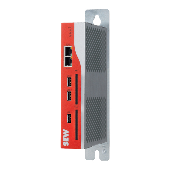
Introduction Requirements Requirements 3.2.1 Required hardware ® MOVI-C CONTROLLER progressive UHX65A-M.. with real-time Ethernet master (with OMC card) in the following designs. ® MOVI-C CONTROLLER Part number UHX65A-M-01-N0 (1 core) 28272870 UHX65A-M-02-N0 (2 core) 28272862 UHX65A-M-04-N0 (4 core) 28272854 3.2.2 Required licenses The following license is required: ®... -
Page 15: Content Of This Document
Introduction Content of this document Content of this document ® This document describes the startup of a MOVI‑C CONTROLLER progressive UHX65A‑M with corresponding fieldbus interface as a PROFINET IO controller or as an EtherNet/IP™ scanner by way of example. Short designation The following short designations are used in this document. -
Page 16: Industrial Ethernet Networks - Basics
Industrial Ethernet networks – Basics TCP/IP addressing and subnets Industrial Ethernet networks – Basics TCP/IP addressing and subnets The address of the TCP/IP protocol is set using the following parameters: • MAC address • IP address • Subnet mask • Standard gateway The addressing mechanisms and subdivision of the TCP/IP networks into subnets are explained in this chapter to help you set the parameters correctly. -
Page 17: Network Class
Industrial Ethernet networks – Basics Network class Network class The first byte of the IP address determines the network class and as such represents the division into network address and node address: Range of val- Network Example: Complete Meaning class network address (byte 1 of the IP address) -
Page 18: Standard Gateway
Industrial Ethernet networks – Basics Standard gateway The class C network with the network address 192.168.10 is further subdivided into the following 2 networks by the subnet mask 255.255.255.128: Network address Node addresses 192.168.10.0 192.168.10.1 – 192.168.10.126 192.168.10.128 192.168.10.129 – 192.168.10.254 The network nodes use a logical AND operation for the IP address and the subnet mask to determine whether there is a communication partner in the same network or in a different network. -
Page 19: Profinet Networks - Recommendations
PROFINET networks – Recommendations Network components PROFINET networks – Recommendations PROFINET (Process Field Network) is the communication standard for the automa- tion of PROFIBUS and PROFINET International (PI). The modular range of functions makes PROFINET a flexible solution for all applica- tions and markets. -
Page 20: Maximum Line Depth
PROFINET networks – Recommendations Maximum line depth Maximum line depth The following table shows the maximum line depth with store and forward switches: Refresh time Maximum line depth The following table shows the maximum line depth with cut-through switches: Refresh time Maximum line depth Network load The following table shows the generated cyclic real-time network load per PROFINET... -
Page 21: Engineering Access Of The Uhx65A-M Controller
Engineering access of the UHX65A-M controller Engineering via the standard engineering interface (X80, X81) Engineering access of the UHX65A-M controller INFORMATION SEW‑EURODRIVE recommends using the standard engineering interface for startup. As soon as the project on the controller has reached a stable state, e.g. when regular updates and downloads of the IEC project are no longer required, the fieldbus inter- face can be used for engineering. -
Page 22: Operating Characteristics With The Profinet
Operating characteristics with the PROFINET PROFINET fieldbus interface Operating characteristics with the PROFINET The controller is a PROFINET IO controller. PROFINET fieldbus interface The supported features of the PROFINET fieldbus interface can be found in the "Tech- nical data" chapter in the operating instructions of the respective controller. The device is connected to the other network nodes using a category 5, class D twis- ted-pair cable in accordance with IEC 11801, edition 2.0. -
Page 23: Profinet Io Controller Stack
Operating characteristics with the PROFINET PROFINET IO controller stack PROFINET IO controller stack The PROFINET IO controller stack of the controller is part of the IEC project. For an executable PROFINET device, you must activate and parameterize a fieldbus station ®... -
Page 24: Bus-Specific Leds For Profinet
Operating characteristics with the PROFINET Bus-specific LEDs for PROFINET Bus-specific LEDs for PROFINET The following table shows an overview of the bus-specific LEDs of the UHX65A-M controller. Controller Status LED ® MOVI‑C CONTROLLER progressive UHX65A‑M L40 (corresponds to status LED "SF") L41 (corresponds to status LED "BF") 7.6.1 Status LEDs "L/A"... -
Page 25: Status Led "L41" (Bf, Bus Fault)
Operating characteristics with the PROFINET Bus-specific LEDs for PROFINET 7.6.3 Status LED "L41" (BF, BUS FAULT) The status LED indicates the status of the PROFINET connection. Status Possible cause Measure Error-free operating state. – The PROFINET device is ex- changing data with the PROFINET controller (Data Exchange state). -
Page 26: Startup With Profinet
Startup with PROFINET Connecting the fieldbus and engineering PC Startup with PROFINET Connecting the fieldbus and engineering PC The engineering PC can be connected to the controller in several ways: • Connection via standard engineering interface X80 (recommended) • Connection to the fieldbus network (e.g. PROFINET) via fieldbus interface X40/ X40/ Ethernet 35952010251... -
Page 27: Setting Up The Profinet Io Controller
Startup with PROFINET Setting up the PROFINET IO controller Setting up the PROFINET IO controller ® 8.4.1 Adding the PROFINET IO-Controller via MOVISUITE ® The following description is the standard fieldbus configuration for MOVISUITE V2.20 or higher. The description of the manual configuration procedure is for experts and should only be used as a workaround •... - Page 28 Startup with PROFINET Setting up the PROFINET IO controller Creating or updating the IEC project 35938845323 • If no IEC project exists, click [Generate new IEC project]. ® • If an IEC project exists, the configuration of the fieldbus option in MOVISUITE quires the IEC project to be updated.
- Page 29 Startup with PROFINET Setting up the PROFINET IO controller Checking the IEC project If the update or project creation is successful, no errors will be shown in the notifica- tion window of the "SEW IEC project generation". There will merely be information about logical devices that have not been created.
-
Page 30: Adding Profinet Io Devices
Startup with PROFINET Setting up the PROFINET IO controller 35943622155 • The default setting of the bus cycle task "Use parent's bus cycle settings" is not al- ways the optimal configuration. For the operation of the fieldbus, select an appro- priate task from the task configuration or create a new task according to the follow- ing example: cyclic task with a call interval of 4 or 10 ms and medium priority When planning the application and the task configuration, please note that the pro-... - Page 31 Startup with PROFINET Setting up the PROFINET IO controller Installing the PROFINET IO device description file (GSDML) In order to be able to use the PROFINET IO device in the IEC project, the correspond- ing device description file (GSDML) must be installed. The device description file is provided by the device manufacturer.
- Page 32 Startup with PROFINET Setting up the PROFINET IO controller 4. Start the controller. To do so, select the menu command [Debug] > [Start] or press the <F5> key. 35943665675 5. The IEC project should now be active. If the PROFINET IO controller symbol is green, the network is ready for operation.
- Page 33 Startup with PROFINET Setting up the PROFINET IO controller 6. Open the context menu of the PROFINET IO controller with a right click and select the option "Scan for devices...". 35944445579 7. A new dialog window will open that lists all connected PROFINET IO devices of the network.
- Page 34 Startup with PROFINET Setting up the PROFINET IO controller 8. If the PROFINET IO device does not contain any IP address (default setting) or if the IP address being retrieved by the device is invalid, the IP configuration can be assigned manually or automatically.
- Page 35 Startup with PROFINET Setting up the PROFINET IO controller 11. The PROFINET IO devices are now available in the IEC project. 35945399947 Log out again. To do so, select the menu command [Online] > [Log out] or press the <ALT> + < F8> keys. Parameterizing PROFINET IO devices and process data 1.
- Page 36 Startup with PROFINET Setting up the PROFINET IO controller 2. Use the menu command [Append device] to select the right entry from the list (e.g. ® ® 5 words for a MOVIDRIVE technology with MOVIKIT Velocity Drive). 35945680139 35945685131 An additional entry has now been created below the PROFINET IO device in the device tree.
- Page 37 Startup with PROFINET Setting up the PROFINET IO controller 35945688075 Find the memory address of the process input and process output data in the "PNIO modules I/O map" tab. 35945693067 Testing the PROFINET IO controller Compile the project using the menu command [Create] > [Generate code], log in using the menu command [Online] > [Log in], and start the application using the menu com- mand [Debug] ...
-
Page 38: Ethernet/Ip™ Networks - Recommendations
EtherNet/IP™ networks – Recommendations Network components EtherNet/IP™ networks – Recommendations The Ethernet Industrial Protocol (EtherNet/IP™) is an open communication standard based on the conventional Ethernet protocols TCP/IP and UDP/IP. EtherNet/IP™ has been defined by the Open DeviceNet Vendor Association (ODVA) and ControlNet International (CI). EtherNet/IP™... -
Page 39: Operating Behavior On Ethernet/Ip
Operating behavior on EtherNet/IP™ EtherNet/IP™ interface Operating behavior on EtherNet/IP™ The controller is an EtherNet/IP™ scanner. 10.1 EtherNet/IP™ interface The supported features of the EtherNet/IP™ fieldbus interface can be found in the "Technical data" chapter in the operating instructions of the respective controller. The device is connected to the other network nodes using a category 5, class D twis- ted-pair cable in accordance with IEC 11801, edition 2.0. -
Page 40: Bus-Specific Leds For Ethernet/Ip
Operating behavior on EtherNet/IP™ Bus-specific LEDs for EtherNet/IP™ 10.3 Bus-specific LEDs for EtherNet/IP™ The following table shows an overview of the bus-specific LEDs of the UHX65A-M controller. Controller Status LED ® MOVI‑C CONTROLLER progressive UHX65A‑M L40 (corresponds to status LED "MS") L41 (corresponds to status LED "NS") 10.3.1 Status LEDs "L/A"... -
Page 41: Status Led "L41" - Ethernet/Ip
Operating behavior on EtherNet/IP™ Bus-specific LEDs for EtherNet/IP™ 10.3.3 Status LED "L41" – EtherNet/IP (NETWORK STATUS) Status LED Operating status Green There is a controlling connection to the fieldbus system. Green, flashing No controlling connection. Green/red, flashing The controller performs a self-test. Red, flashing The previously established controlling connection has timed out. -
Page 42: Startup With Ethernet/Ip
Startup with EtherNet/IP™ Connecting the fieldbus and engineering PC Startup with EtherNet/IP™ 11.1 Connecting the fieldbus and engineering PC The engineering PC can be connected to the controller in several ways: • Connection via standard engineering interface X80 (recommended) • Connection to the fieldbus network (e.g. -
Page 43: Setting Up The Ethernet/Ip Scanner
Startup with EtherNet/IP™ Setting up the EtherNet/IP scanner 11.4 Setting up the EtherNet/IP scanner ® 11.4.1 Adding the EtherNet/IP™ scanner via MOVISUITE ® The following description is the standard fieldbus configuration for MOVISUITE V2.20 or higher. The description of the manual configuration procedure is for experts and should only be used as a workaround •... - Page 44 Startup with EtherNet/IP™ Setting up the EtherNet/IP scanner Creating or updating the IEC project 35938845323 • If no IEC project exists, click [Generate new IEC project]. ® • If an IEC project exists, the configuration of the fieldbus option in MOVISUITE quires the IEC project to be updated.
- Page 45 Startup with EtherNet/IP™ Setting up the EtherNet/IP scanner Checking the IEC project If the update or project creation is successful, no errors will be shown in the notifica- tion window of the "SEW IEC project generation". There will merely be information about logical devices that have not been created.
- Page 46 Startup with EtherNet/IP™ Setting up the EtherNet/IP scanner Configuring the EtherNet/IP™ scanner network • Adjust the EtherNet/IP™ and network settings to your requirements in the "Gen- eral" tab. 36123627915 • The default setting of the bus cycle task "Use parent's bus cycle settings" is not al- ways the optimal configuration.
-
Page 47: Parameterizing Already Present Ethernet/Ip™ Devices
Startup with EtherNet/IP™ Setting up the EtherNet/IP scanner 11.4.2 Parameterizing already present EtherNet/IP™ devices You must assign a valid IP parameterization to the EtherNet/IP™ devices. Further device-specific settings may also be required. Please contact the respective device manufacturer. This can be carried out using the "BootP DHCP EtherNet/IP Commissioning Tool" software from Rockwell Automation (see following image) or via the manufacturer's tool, for example. - Page 48 Startup with EtherNet/IP™ Setting up the EtherNet/IP scanner To install the required device description files, select the menu command [Tools] > [Device repository]. 36123936523 Appending a device Proceed as follows: 1. Select the menu command [Append device]. 36124456075 ® Manual – MOVI-C CONTROLLER progressive UHX65A-M...
- Page 49 Startup with EtherNet/IP™ Setting up the EtherNet/IP scanner 2. Select the desired device from the list. 36261146251 The EtherNet/IP™ devices are now available in the IEC project. 36124465291 ® Manual – MOVI-C CONTROLLER progressive UHX65A-M...
- Page 50 Startup with EtherNet/IP™ Setting up the EtherNet/IP scanner Parameterizing EtherNet/IP™ devices and process data Proceed as follows: 1. Parameterize the EtherNet/IP™ device. To do so, adjust the EtherNet/IP™ and network settings to your requirements in the "General" tab. 36499815435 2. Adjust the EtherNet/IP™ and network settings to your requirements in the "Con- nections"...
- Page 51 Startup with EtherNet/IP™ Setting up the EtherNet/IP scanner 4. Compile the project using the menu command [Create] > [Generate code], log in using the menu command [Online] > [Log in], and start the application using the menu command [Debug] > [Start]. After a brief initialization phase, the fieldbus and the appended stations are ready for operation and a green symbol is displayed.
- Page 52 Startup with EtherNet/IP™ Setting up the EtherNet/IP scanner 4. Start the controller. To do so, select the menu command [Debug] > [Start] or press the <F5> key. 36124408459 5. The IEC project should now be active. If the EtherNet/IP™ scanner symbol is green, the network is ready for operation.
-
Page 53: Technical Data
Technical data PROFINET IO controller communication protocol Technical data 12.1 PROFINET IO controller communication protocol Parameter Description Maximum number of PROFINET • 128 (RT) IO devices/AR (Application Rela- • 64 (IRT) tion) Maximum number of PROFINET • 16 AR maximum at send cycle of 1 ms IO devices/AR depending on send •... -
Page 54: Ethernet/Ip™ Scanner Communication Protocol
Technical data EtherNet/IP™ scanner communication protocol Parameter Description PROFINET specification • Implemented acc. to V2.3 ED2 MU3 • Legacy startup acc. to PROFINET specifica- tion V2.2 supported Baud rate 100 Mbit/s full duplex Data transport layer Ethernet II, IEEE 802.3 Configuration file Maximum 1 megabyte Limitations The following functions are not supported:... - Page 55 Technical data EtherNet/IP™ scanner communication protocol Parameter Description Maximum number of "Unscheduled 1400 bytes per telegram Data" UCMM, Class 3 Supported Explicit messages, client and Get_Attribute_Single/All server services Set_Attribute_Single/All Quick connect Supported Predefined standard objects • Identity object • Message router object •...
-
Page 56: Index
Index Index Network components........ 38 Network load .......... 38 Assembly EtherNet/IP™ scanner communication protocol . 54 Safety notes ........... 11 Auto-crossing .......... 22, 39 Auto-negotiation .......... 22, 39 Functional safety technology Safety note ............. 11 Cable length between network stations.. 22, 39 CIP™... - Page 57 Index Section-related safety notes ........ 7 Short designation in the document ...... 15 Product names ............ 8 Signal words in safety notes........ 7 PROFINET alarms.......... 23 Standard gateway .......... 18 PROFINET IO controller communication protocol Status LEDs ............... 53 L/A (Link/Activity).......... 40 PROFINET network..........
- Page 60 SEW-EURODRIVE—Driving the world SEW-EURODRIVE GmbH & Co KG Ernst-Blickle-Str. 42 76646 BRUCHSAL GERMANY Tel. +49 7251 75-0 Fax +49 7251 75-1970 sew@sew-eurodrive.com www.sew-eurodrive.com...
Need help?
Do you have a question about the MOVI-C UHX65A-M and is the answer not in the manual?
Questions and answers