Table of Contents

Subscribe to Our Youtube Channel
Related Manuals for SEW-Eurodrive MOVI-C MFC1 FHX25A-N


Summary of Contents for SEW-Eurodrive MOVI-C MFC1 FHX25A-N
- Page 1 *26872137_1221* Drive Technology \ Drive Automation \ System Integration \ Services Operating Instructions Decentralized Motion and Logic Controller ® MOVI-C FIELD CONTROLLER standard/advanced MFC1../FHX Edition 12/2021 26872137/EN...
- Page 2 SEW-EURODRIVE—Driving the world...
-
Page 3: Table Of Contents
Table of contents Table of contents General information........................ 8 About this documentation .................... 8 Other applicable documentation .................. 8 Structure of the safety notes ................... 8 1.3.1 Meaning of signal words ................ 8 1.3.2 Structure of section-related safety notes............ 8 1.3.3 Structure of embedded safety notes .............. 9 Decimal separator in numerical values ................ 9 Rights to claim under limited warranty ................ 9 Product names and trademarks.................. 10... - Page 4 Table of contents 3.7.2 Type designation of the electronics cover (controller)........ 24 Example nameplate and type designation of the connection unit......... 25 3.8.1 Nameplate .................... 25 3.8.2 Type designation of the connection unit............ 25 Mechanical installation ...................... 26 Installation notes ...................... 26 Required tools and resources .................. 26 Tolerances for torque ratings .................. 26 Installation requirements.................... 26...
- Page 5 Table of contents 5.8.1 Installation with separately routed Ethernet cable........ 48 5.8.2 Installation with PA hybrid cable .............. 50 5.8.3 Installation with PAC hybrid cable.............. 51 EMC cable glands...................... 52 5.9.1 Cable shielding..................... 52 5.9.2 Assembly of EMC cable glands .............. 52 5.10 Plug connectors ...................... 53 5.10.1...
- Page 6 Table of contents Resetting fault messages.................... 110 Description of status and operating displays .............. 111 8.3.1 PROFINET IO LED displays .............. 111 8.3.2 LEDs for EtherNet/IP™, Modbus TCP ............ 112 8.3.3 General LEDs..................... 112 8.3.4 Bus-specific LEDs for PROFINET IO ............ 115 8.3.5 Bus-specific LEDs for EtherNet/IP™...
- Page 7 Table of contents 10.3.2 Environmental conditions ................ 139 10.3.3 Derating factors .................. 140 10.3.4 Current carrying capacity of terminals............ 140 10.3.5 Technical data for PROFINET IO interface.......... 141 10.3.6 Technical data for the EtherNet/IP™, Modbus TCP interface.... 142 10.4 Port overview ...................... 143 10.4.1 Interface description ...................
-
Page 8: General Information
General information About this documentation General information About this documentation The documentation at hand is the original. This documentation is an integral part of the product. The documentation is intended for all employees who perform work on the product. Make sure this documentation is accessible and legible. Ensure that persons respon- sible for the systems and their operation as well as persons who work on the product independently have read through the documentation carefully and understood it. -
Page 9: Structure Of Embedded Safety Notes
General information Decimal separator in numerical values Meaning of the hazard symbols The hazard symbols in the safety notes have the following meaning: Hazard symbol Meaning General hazard Warning of dangerous electrical voltage Warning of hot surfaces Warning of automatic restart 1.3.3 Structure of embedded safety notes Embedded safety notes are directly integrated into the instructions just before the de-... -
Page 10: Product Names And Trademarks
General information Product names and trademarks Product names and trademarks The brands and product names in this documentation are trademarks or registered trademarks of their respective titleholders. 1.6.1 Trademark of Beckhoff Automation GmbH EtherCAT is a registered trademark and patented technology, licensed by Beckhoff ®... -
Page 11: Safety Notes
Safety notes Preliminary information Safety notes Preliminary information The following general safety notes serve the purpose of preventing injury to persons and damage to property. They primarily apply to the use of products described in this documentation. If you use additional components, also observe the relevant warning and safety notes. -
Page 12: Target Group
Safety notes Target group Target group Specialist for me- Any mechanical work may be performed only by adequately qualified specialists. Spe- chanical work cialists in the context of this documentation are persons who are familiar with the design, mechanical installation, troubleshooting, and maintenance of the product who possess the following qualifications: •... -
Page 13: Designated Use
Do not use the product as a climbing aid. 2.5.1 Restrictions under the European WEEE Directive 2012/19/EU You may use options and accessories from SEW-EURODRIVE exclusively in connec- tion with products from SEW-EURODRIVE. Functional safety technology The product must not perform any safety functions without a higher-level safety sys- tem unless explicitly allowed by the documentation. -
Page 14: Restrictions Of Use
Safety notes Installation/assembly Protect the product from excessive mechanical strain. The product and its mounted components must not protrude into the path of persons or vehicles. Ensure that no components are deformed or no insulation spaces are modified, particularly during transportation. -
Page 15: Protective Separation
Safety notes Protective separation Protective separation The product meets all requirements for protective separation of power and electronics connections in accordance with EN 61800-5-1. The connected signal circuits must meet requirements according to SELV (Safety Extra Low Voltage) or PELV (Protective Extra Low Voltage) to ensure protective separation. -
Page 16: Startup/Operation
Safety notes Startup/operation 2.11 Startup/operation Observe the safety notes in chapters Startup and "Operation" (→ 2 109) in this docu- mentation. Make sure the connection boxes are closed and screwed before connecting the sup- ply voltage. Depending on the degree of protection, products may have live, uninsulated, and sometimes moving or rotating parts as well as hot surfaces during operation. -
Page 17: Switch Disconnector
Device structure MOVI-C® FIELD CONTROLLER standard/advanced Device structure MOVI-C® FIELD CONTROLL standard/ advanced ® MOVI-C FIELD CONTROLLER Standard/Advanced The MOVI-C FIELD CONTROLLER consists of a decentralized controller (referred to ® as electronics cover in the following) and a connection box with field distributor func- tionality. -
Page 18: Cable Entry Position
Device structure Cable entry position Cable entry position 3.2.1 MFC1.. design The following cables entries are possible for the device: • Position X + 2 + 3 – X: 2 × M25 × 1.5 + 2 × M16 × 1.5 –... -
Page 19: Nameplate Position
Device structure Nameplate position Nameplate position 3.3.1 MFC1.. design The following nameplate positions are possible for the device: • Nameplate of the complete device: Position X • Optional nameplate: Position 2 The following figure shows examples of the nameplate position: ®... -
Page 20: Type Designation
Device structure Example nameplate and type designation 3.4.2 Type designation The following table shows the type designation of the MOVI-C FIELD CONTROLLER ® standard/advanced: Product family MFC = MOVI-C FIELD CONTROLLER ® Variant /SBus devices ® PLUS 1 = Device variant 1 for EtherCAT Front module 0 = Closed –... -
Page 21: Examples For The Optional Nameplate "Plug Connector Positions
Device structure Examples for the optional nameplate "Plug connector positions" Examples for the optional nameplate "Plug connector positions" 3.5.1 MFC1.. design The following figure shows an example of the optional nameplate "Plug connector pos- itions": S0#: 01.7659637451.0001.20 X2327_1 X1203_1 X1203_2 X2313 X4251_1 31659772811... -
Page 22: Mfc1
Device structure Electronics Electronics 3.6.1 Connection box and electronics cover (internal) MFC1.. design The following figure shows the connection box and the bottom side of the electronics cover (controller): [10] [11] [14] [13] [12] [12] 9007227774833675 Cable glands Connection box Connection for supply system Line connection of drive units Connector of connection unit for electronics cover (controller) -
Page 23: Electronics Cover (Outside)
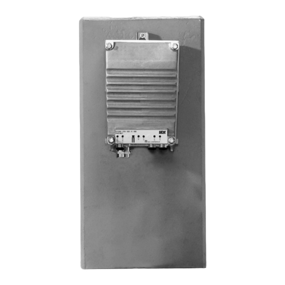
Device structure Electronics 3.6.2 Electronics cover (outside) The following figure shows an example of the electronics cover (controller) design: 9007227776741899 LED displays Plug connectors Operating Instructions – MOVI-C FIELD CONTROLLER standard/advanced ®... -
Page 24: Example Nameplate And Type Designation Of The Electronics
Device structure Example nameplate and type designation of the electronics Example nameplate and type designation of the electronics 3.7.1 Nameplate The following figure shows an example of a nameplate of the electronics cover (con- troller). For the structure of the type designation, refer to chapter "Type designation of the electronics cover (controller)". -
Page 25: Example Nameplate And Type Designation Of The Connection Unit
Device structure Example nameplate and type designation of the connection unit Example nameplate and type designation of the connection unit 3.8.1 Nameplate The following figure gives an example of a nameplate of the connection unit. For the structure of the type designation, refer to chapter "Type designation of the connection unit". -
Page 26: Mechanical Installation
Mechanical installation Installation notes Mechanical installation Installation notes INFORMATION Adhere to the safety notes during installation. WARNING Improper installation/disassembly of the device and mount-on components. Serious injuries. • Adhere to the notes about installation and disassembly. Required tools and resources •... -
Page 27: Installing The Device
Mechanical installation Installing the device Installing the device 4.5.1 Notes • Only install the device on a level, low-vibration, and torsionally rigid support struc- ture. • Check the validity of the degree of protection using the information in the operating instructions and the data on the nameplate. - Page 28 Mechanical installation Installing the device Installing the electronics cover • Use only electronics covers that match the size. • Be careful not to tilt the electronics cover when placing it on the connection box. MFC1.. design The following figure shows how to correctly place the electronics cover onto the con- nection box: 28776924683 Minimum installation clearance...
- Page 29 MFC1.. design with switch disconnector The following figure shows the minimum clearances when installing the device: 32451191307 INFORMATION SEW-EURODRIVE recommends a minimum clearance of 100 mm for access to the switch disconnector. Removing the electronics cover MFC1.. design The following figure shows how you can loosen the electronics cover from the connec-...
-
Page 30: Mounting The Device
Mechanical installation Mounting the device Mounting the device 4.6.1 MFC1.. design The following figure shows the mounting dimensions for the device: 32522307211 Hex head screws 3 × M6 (torque: 10 Nm) Operating Instructions – MOVI-C FIELD CONTROLLER standard/advanced ®... -
Page 31: Mounting The Device With Mounting Panel M01
Mechanical installation Mounting the device with mounting panel M01 Mounting the device with mounting panel M01 4.7.1 MFC1.. design The following figure shows the mounting dimensions for the device with mounting panel M01: 31263212171 Mounting panel M01 (stainless steel) (available for delivery from SEW‑EURODRIVE, part number: 28266129, scope of delivery: 2 spacers, 4 hex head screws M6 ×... -
Page 32: Mfc1.. Design
Mechanical installation Tightening torques Tightening torques WARNING Risk of burns due to hot surfaces. Serious injuries. • Let the devices cool down before touching them. 4.8.1 Blanking plugs Tighten the plastic blanking plugs included in the delivery by SEW‑EURODRIVE with 2.5 Nm: MFC1.. -
Page 33: Cable Glands
Mechanical installation Tightening torques 4.8.2 Cable glands Tightening torques Tighten the EMC cable glands optionally supplied by SEW‑EURODRIVE to the fol- lowing torques: Screw fitting Part Content Size Outer Tighten- number cable di- ameter torque 18204783 10 pieces EMC cable glands M16 × 1.5 5 to 9 mm 4.0 Nm (nickel-plated brass) 18204805 10 pieces... -
Page 34: Electronics Cover
Mechanical installation Tightening torques 4.8.3 Electronics cover Proceed as follows when installing the electronics cover: Insert the screws and tighten them in diametrically opposite sequence step by step with a tightening torque of 6.0 Nm. MFC1.. design The following figure shows how to screw on the electronics cover: 9007227787439499 Operating Instructions –... -
Page 35: Electrical Installation
Electrical installation Installation planning taking EMC aspects into account Electrical installation Installation planning taking EMC aspects into account 5.1.1 Notes on arranging and routing installation components The correct operation of decentralized inverters depends on selecting the correct cables, providing correct grounding, and on a properly functioning equipotential bond- ing. -
Page 36: Equipotential Bonding
Electrical installation Installation planning taking EMC aspects into account 5.1.4 Equipotential bonding Regardless of the PE connection, it is essential that low-impedance, HF-capable equipotential bonding is provided (see also EN 60204-1 or DIN VDE 0100-540): • Provide for a connection over a wide area between the device and the mounting plate. -
Page 37: Equipotential Bonding At The Connection Box
Electrical installation Equipotential bonding at the connection box Equipotential bonding at the connection box Another option for HF-capable equipotential bonding at a connection box is the follow- ing cable gland with M6 stud bolt: 3884960907 Tightening torque Tightening torque Part number of the cable gland of the M6 nut for stud bolt... -
Page 38: Installation Instructions
Electrical installation Installation instructions Installation instructions 5.3.1 Permitted voltage systems Information on voltage systems Information on permissibility TN and TT systems – voltage systems Can be used without restrictions with directly grounded star point IT systems – voltage systems with non- Contact SEW‑EURODRIVE grounded star point Voltage systems with grounded outer... -
Page 39: Permitted Cable Cross Section Of Terminals
Electrical installation Installation instructions 5.3.3 Permitted cable cross section of terminals Line terminals X1_a, X1_b Observe the permitted cable cross sections for installation: Line terminals X1_a, Without conductor end With conductor end X1_b sleeve sleeve (with or without plastic collar) Connection cross sec- 0.5 mm – 6 mm... -
Page 40: Actuating The Line Terminals X1_A, X1_B
Electrical installation Installation instructions 5.3.4 Actuating the line terminals X1_a, X1_b Adhere to the following sequence when actuating the line terminals X1_a and X1_b: Line terminals X1_a and X1_b (the following figure shows a schematic illustration) 25649924107 5.3.5 Actuating control terminals X9 Adhere to the following sequence when actuating the X9 control terminals: X9 control terminals (the following figure shows a schematic illustration) 28713963147... -
Page 41: Line Contactor
Electrical installation Installation instructions 5.3.7 Line contactor NOTICE Non-compliance with the minimum switch-on/switch-off times. Damage to the device. • Keep the supply system switched off for 10 s before switching the power back • Do not switch the supply system off and on more than once per minute. •... -
Page 42: Notes On Pe Connection
Electrical installation Installation instructions 5.3.8 Notes on PE connection WARNING Electric shock due to incorrect connection of PE. Severe or fatal injuries. • The permitted tightening torque for the screw is 2.0 to 2.4 Nm. • Observe the following notes regarding PE connection. Impermissible assembly Recommendation: Assembly with solid connecting... -
Page 43: Installation Above 1000 M Asl
Electrical installation Installation instructions 5.3.9 Installation above 1000 m asl You can install the drive units at altitudes from 1000 m to a maximum of 3800 m above sea level provided that the following conditions are met. • The nominal current I is reduced due to the reduced cooling above 1000 m (see chapter "Technical data and dimension sheets"). -
Page 44: Installation Topology (Installation With Pac Hybrid Cable)
Electrical installation Installation topology (installation with PAC hybrid cable) Installation topology (installation with PAC hybrid cable) The following figure shows a basic installation topology with the device: Control 24 V Supply system Back-up fuse/line Control cabinet level protection Field level MOVI-C®... -
Page 45: Terminal Assignment
Electrical installation Terminal assignment Terminal assignment The following figure shows the terminal assignment in the connection box of the device: X1_a 11 12 13 11 12 13 14 X1_b 21 22 23 24 11 12 13 32854784011 Assignment Terminal Name Marking Function Brown... - Page 46 Electrical installation Terminal assignment Assignment Terminal Name Marking Function +24V – DC 24 V voltage control terminals +24V – DC 24 V voltage +24V – DC 24 V voltage +24V – DC 24 V voltage +24V – DC 24 V voltage CAN_H – CAN data cable (high), electrically isolated – RS485 data cable (+), electrically isolated 0V24...
-
Page 47: Connection Diagram
Electrical installation Connection diagram Connection diagram The following figure shows the connections of the device: F11/F12/F13 MOVI-C® FIELD CONTROLLER MFC1../FHX X1_a Line terminals X1_b EtherCAT®/ X43_1 PLUS SBus Line terminals for connecting drive units Mini IO X43_2 (can be optionally switched off by switch disconnector) Fieldbus X4233_1... -
Page 48: Communication Interfaces
Electrical installation Communication interfaces Communication interfaces 5.7.1 CAN system bus The communication interface is available for project-specific use. Before using the communication interface, contact SEW‑EURODRIVE Service. MOVILINK ® , CANopen and the control of generation B inverters cannot be implemen- ted via the communication interface. 5.7.2 RS485 interface The communication interface is available for project-specific use. - Page 49 Electrical installation Cable routing and cable shielding MFC1.. design The following figure shows the connections of the device: Supply system 24 V PLUS EtherCAT®/SBus Supply PLUS system EtherCAT®/SBus Drive units Supply system RS485 9007231710074123 Operating Instructions – MOVI-C FIELD CONTROLLER standard/advanced ®...
-
Page 50: Installation With Pa Hybrid Cable
Electrical installation Cable routing and cable shielding 5.8.2 Installation with PA hybrid cable Notes on cable routing and shielding – Recommended cable routing Note the following when routing and shielding the cables: • Cable selection – For cable selection, note chapter "Technical data and dimension sheets / con- nection cables"... -
Page 51: Installation With Pac Hybrid Cable
Electrical installation Cable routing and cable shielding 5.8.3 Installation with PAC hybrid cable Notes on cable routing and shielding – Recommended cable routing Note the following when routing and shielding the cables: • Cable selection – For cable selection, note chapter "Technical data and dimension sheets / con- nection cables"... -
Page 52: Emc Cable Glands
Electrical installation EMC cable glands EMC cable glands 5.9.1 Cable shielding For shielded cables, it is best to use EMC cable glands to connect the shield. EMC cable glands are available as option. 31658642315 5.9.2 Assembly of EMC cable glands Assemble the EMC cable glands supplied by SEW‑EURODRIVE according to the fol- lowing figure: 18014401170670731... -
Page 53: Plug Connectors
Electrical installation Plug connectors 5.10 Plug connectors 5.10.1 Representation of connections The wiring diagrams of the plug connectors depict the contact end of the connections. 5.10.2 Connection cables INFORMATION For more information about cable types, see chapter "Technical data". Connection cables are not included in the scope of delivery. Prefabricated cables for connecting SEW‑EURODRIVE components can be ordered. - Page 54 Using prefabricated cables with plug connectors SEW-EURODRIVE uses prefabricated cables for certifications, type tests and ap- proval of the units. The cables available from SEW-EURODRIVE meet all the require- ments necessary for the functions of the unit and the connected components. The devices under consideration are always the basic devices including all connected components and corresponding connection cables.
-
Page 55: Plug Connector Positions, Connection Box
Electrical installation Plug connectors 5.10.3 Plug connector positions, connection box MFC1.. design Cable entries M25 The following figure depicts the possible plug connector positions for the M25 cable entries: X1203_1 X1203_1 X1203_2 X1203_2 X1203_2 X1203_1 X2203_1 X2203_2 X2326_2 X2326_1 X2327_1 X2327_2 28831731211 Plug connector... - Page 56 Electrical installation Plug connectors Plug connector Not together at a position with the Designation Coding ring/ Function Position plug connector: color X1203_2 Black X or 2 – AC 400 V connection • X2326_1 X2203_1 Black AC 400 V connection drive units • X2327_1 X2203_2 Black •...
- Page 57 Electrical installation Plug connectors Cable entries M16 The following figure depicts the possible plug connector positions for the M16 cable entries: X1523 X1523 X1523 X2313 X2313 X2313 X2313_1 X2313_2 X2313_2 X4251_1 X4251_2 X4251_1 X4251_1 9007228086476171 Plug connector Not together at a position with the Designation Coding ring/...
-
Page 58: Plug Connector Positions At The Electronics Cover
Electrical installation Plug connectors Plug connector Not together at a position with the Designation Coding ring/ Function Position plug connector: color X2313_1 Black Optional DC 24 V backup voltage - output connection of drive units pressure compensa- tion X2313_2 Black Optional DC 24 V backup voltage - output connection of drive units pressure compensa- tion... -
Page 59: Plug Connector Variants
Electrical installation Plug connectors 5.10.5 Plug connector variants M12 plug connector at the connection box M12 plug connectors at the connection box are pre-installed so they match the con- nection cables provided by SEW‑EURODRIVE. Customers can adjust the orientation of plug connectors if required. The following figure shows a schematic illustration with the permitted tightening torques: 6 Nm... - Page 60 Electrical installation Plug connectors M12 plug connector with mating connector 0.4 – 0.6 Nm 32845364363 INFORMATION The M12 plug connectors are usually tightened with a torque of 0.4 – 0.6 Nm. Ob- serve the data sheet of the used prefabricated cables. Operating Instructions –...
- Page 61 Electrical installation Plug connectors M23 plug connector CAUTION Loss of the guaranteed degree of protection. Potential damage to property. • Remove the union nut from the M23 plug connector using 3 Nm. • Between plug connector and bushing is a gap of 2 mm. M23 plug connectors are available in the plug connector design "Straight".
-
Page 62: Using Plug Connectors Assembled By Yourself
Electrical installation Plug connectors 5.10.6 Using plug connectors assembled by yourself M23 plug connector by TE connectivity – Intercontec Products The power plug connectors for assembling connection cables yourself, and the corre- sponding assembly tool set is available for order from TE Connectivity - Intercontec products. - Page 63 The following tables contains the part numbers and purchase order numbers of the mini-I/O plug connectors for customer assembly of mini I/O connection cables. Plug connector Cable Cable Purchase order num- Part number Outer diameter Category SEW-EURODRIVE Core cross section TE Connectivity (quantity) Intercontec products (quantity) Industrial mini I/O CAT5e 1-2350278-1 (60 25697064 4.7 –- 5.7 mm...
-
Page 64: Assignment Of Optional Plug Connectors
Electrical installation Assignment of optional plug connectors 5.11 Assignment of optional plug connectors WARNING Electric shock when disconnecting or connecting voltage-carrying plug connectors. Severe or fatal injuries • Switch off the line voltage. • Never plug or unplug plug connectors while they are energized. 5.11.1 X1203_1 and X1203_2: AC 400 V connection The following table shows information about this connection:... - Page 65 Electrical installation Assignment of optional plug connectors Connection cables The following tables list the cables available for this connection: Cable cross section 1.5 mm Connection cable Conformity/ Cable type Length/in- Cable part num- stallation cross sec- type tion/operat- ing voltage HELUKABEL Variable ®...
- Page 66 Electrical installation Assignment of optional plug connectors Connection cable Conformity/ Cable type Length/in- Cable part num- stallation cross sec- type tion/operat- ing voltage HELUKABEL Variable ® 2.5 mm MULTIFLEX ® 18153275 – 512 AC 500 V M23, coding M23, coding ring: black, ring: black, male male HELUKABEL...
- Page 67 Electrical installation Assignment of optional plug connectors Cable cross section 4.0 mm Connection cable Conformity/ Cable type Length/in- Cable part num- stallation cross sec- type tion/operat- ing voltage HELUKABEL Variable ® 4.0 mm TOPFLEX – ® 18127487 600-PVC AC 500 V 18133975 M23, coding M23, coding ring: black, ring: black,...
- Page 68 Electrical installation Assignment of optional plug connectors Connection cable Conformity/ Cable type Length/in- Cable part num- stallation cross sec- type tion/operat- ing voltage HELUKABEL Variable ® 4.0 mm TOPFLEX – ® 18133983 611-PUR AC 500 V (halogen-free) Open M23, coding ring: black, male HELUKABEL Variable ®...
- Page 69 Electrical installation Assignment of optional plug connectors Connection of cables with open end The following table shows the core assignment of cables with the following part num- bers: Part numbers 18180094, 18127479, 18133967, 18153283, 18153291, 18127495, 18133983, 18153321, 18153348 Assembly Open cable end Description Prefabricated plug...
-
Page 70: X2203_1 And X2203_2: Ac 400 V Connection
Electrical installation Assignment of optional plug connectors 5.11.2 X2203_1 and X2203_2: AC 400 V connection The following table shows information about this connection: Function AC 400 V connection for supplying connected devices and drive units. Connection type M23, SEW insert, 723 series, SpeedTec equipment, company: TE Connectivity - Intercontec products, female, coding ring: black, protected against contact Connection diagram Assignment... - Page 71 Electrical installation Assignment of optional plug connectors Connection cables The following tables list the cables available for this connection: Cable cross section 1.5 mm Connection cable Conformity/ Cable type Length/in- Cable part num- stallation cross sec- type tion/operat- ing voltage HELUKABEL Variable ®...
- Page 72 Electrical installation Assignment of optional plug connectors Connection cable Conformity/ Cable type Length/in- Cable part num- stallation cross sec- type tion/operat- ing voltage HELUKABEL Variable ® 2.5 mm MULTIFLEX ® 18153275 – 512 AC 500 V M23, coding M23, coding ring: black, ring: black, male male HELUKABEL...
- Page 73 Electrical installation Assignment of optional plug connectors Cable cross section 4.0 mm Connection cable Conformity/ Cable type Length/in- Cable part num- stallation cross sec- type tion/operat- ing voltage HELUKABEL Variable ® 4.0 mm TOPFLEX – ® 18127487 600-PVC AC 500 V 18133975 M23, coding M23, coding ring: black, ring: black,...
- Page 74 Electrical installation Assignment of optional plug connectors Connection cable Conformity/ Cable type Length/in- Cable part num- stallation cross sec- type tion/operat- ing voltage HELUKABEL Variable ® 4.0 mm TOPFLEX – ® 18133983 611-PUR AC 500 V (halogen-free) Open M23, coding ring: black, male HELUKABEL Variable ®...
- Page 75 Electrical installation Assignment of optional plug connectors Connection of cables with open end The following table shows the core assignment of cables with the following part num- bers: Part numbers 18180094, 18127479, 18133967, 18153283, 18153291, 18127495, 18133983, 18153321, 18153348 Assembly Open cable end Description Prefabricated plug...
-
Page 76: X2326_1 And X2326_2: Pac Connection For Ac 400 V, Dc 24 V Backup Voltage And Communication, Output
Electrical installation Assignment of optional plug connectors 5.11.3 X2326_1 and X2326_2: PAC connection for AC 400 V, DC 24 V backup voltage and communication, output The following table shows information about this connection: Function PAC connection for AC 400 V, DC 24 V backup voltage and Ethernet (OUT) Connection type M23, female, female thread with union nut, company: TE Connectivity - Intercontec products, SEW insert, series 723, SpeedTec equipment, coding ring: gray/green,... - Page 77 Electrical installation Assignment of optional plug connectors Connection cables The following tables list the cables available for this connection: Cable cross section 2.5 mm Connection cable Conformity/ Cable type Length/in- Cable part num- stallation cross sec- type tion/operat- ing voltage CE/UL: HELUKABEL Variable ®...
- Page 78 Electrical installation Assignment of optional plug connectors Cable cross section 4.0 mm Connection cable Conformity/ Cable type Length/in- Cable part num- stallation cross sec- type tion/operat- ing voltage CE/UL: HELUKABEL Variable ® 4.0 mm 28129318 Li9YYö AC 500 V M23, male, M23, female, Connection coding ring: coding ring: cable/exten-...
- Page 79 Electrical installation Assignment of optional plug connectors Connection of cables with open end The following table shows the core assignment of cables with the following part num- bers: Part numbers 28113780, 28113802, 28113799, 28113810 Assembly Open cable end Description Prefabricated plug connectors M23, male, male thread, coding ring:...
- Page 80 Electrical installation Assignment of optional plug connectors Assembly Open cable end Description Prefabricated plug connectors M23, male, male thread, coding ring: gray/green Core Identi- Assembly Signal Contact color/ fication core cross section Orange Not pre- Ethernet RX- 0.34 mm fabricated Operating Instructions –...
-
Page 81: X2327_1 And X2327_2: Pa Connection For Ac 400 V And Dc 24 V Backup Voltage, Output
Electrical installation Assignment of optional plug connectors 5.11.4 X2327_1 and X2327_2: PA connection for AC 400 V and DC 24 V backup voltage, output The following table shows information about this connection: Function PA connection for AC 400 V and 24 V backup voltage (OUT) Connection type M23, female, female thread with union nut, SEW insert, 723 series, SpeedTec equip- ment, company: TE Connectivity –... - Page 82 Electrical installation Assignment of optional plug connectors Connection cables The following tables list the cables available for this connection: Cable cross section 2.5 mm Connection cable Conformity/ Cable type Length/in- Cable part num- stallation cross sec- type tion/operat- ing voltage CE/UL: HELUKABEL Variable ®...
- Page 83 Electrical installation Assignment of optional plug connectors Cable cross section 4.0 mm Connection cable Conformity/ Cable type Length/in- Cable part num- stallation cross sec- type tion/operat- ing voltage CE/UL: HELUKABEL Variable ® 4.0 mm 28129334 Li9YYö AC 500 V M23, male, M23, female, coding ring: coding ring: black/green black/green...
- Page 84 Electrical installation Assignment of optional plug connectors Connection of cables with open end The following table shows the core assignment of cables with the following part num- bers: Part numbers 28114426, 28114442, 28114434, 28114450 Assembly Open cable end Description Prefabricated plug connectors Core Identi-...
-
Page 85: X1523: Dc 24 V Backup Voltage, Input
Electrical installation Assignment of optional plug connectors 5.11.5 X1523: DC 24 V backup voltage, input The following table shows information about this connection: Function DC 24 V backup voltage input Connection type M12, 5‑pin, male, L‑coded, color: light gray Connection diagram Assignment Contact Signal Description +24V/L1... - Page 86 Electrical installation Assignment of optional plug connectors Connection cables The following table provides an overview of the cables available for this connection: Connection cable Conformity/ Cable type Length/in- Cable part num- stallation cross sec- type tion/operat- ing voltage CE/UL: HELUKABEL Variable ®...
- Page 87 Electrical installation Assignment of optional plug connectors Connection of cables with open end The following table shows the core assignment of cables with the following part num- ber: Part numbers 28117786 Assembly Open cable end Description Prefabricated plug connectors Core Identi- Assembly Signal...
-
Page 88: X2313, X2313_1 And X2313_2: Dc 24 V Backup Voltage, Output
Electrical installation Assignment of optional plug connectors 5.11.6 X2313, X2313_1 and X2313_2: DC 24 V backup voltage, output The following table shows information about this connection: Function DC 24 V output backup voltage Connection type M12, 5‑pin, female, L‑coded, color: light gray Connection diagram Assignment Contact... - Page 89 Electrical installation Assignment of optional plug connectors Connection cables The following table provides an overview of the cables available for this connection: Connection cable Conformity/ Cable type Length/in- Cable part num- stallation cross sec- type tion/operat- ing voltage CE/UL: HELUKABEL Variable ®...
- Page 90 Electrical installation Assignment of optional plug connectors Connection of cables with open end The following table shows the core assignment of cables with the following part num- ber: Part numbers 28117751, 28117778 Assembly Open cable end Description Prefabricated plug connector Core Identi- Assembly...
-
Page 91: X4251_1 And X4251_2: Ethercat ® /Sbus Plus , Output
Electrical installation Assignment of optional plug connectors ® PLUS 5.11.7 X4251_1 and X4251_2: EtherCAT /SBus , output The following table shows information about this connection: Function Output EtherCAT /SBus ® PLUS Connection type M12, female, D-coded, female thread, Speedcon, protected against contact, color: turquoise Connection diagram Assignment... -
Page 92: Assignment Of The Plug Connectors In The Connection Unit
Electrical installation Assignment of the plug connectors in the connection unit 5.12 Assignment of the plug connectors in the connection unit ® PLUS 5.12.1 X43_1 and X43_2: Connection of EtherCAT /SBus for drive units (subnetwork) The following table shows information about this connection: Function Connection for Ethernet-based fieldbus or subnetwork Connection type... - Page 93 Electrical installation Assignment of the plug connectors in the connection unit Cable cross section 0.14 mm Connection cable Conformity/ Cable type Length/in- Cable part num- stallation cross sec- type tion/operat- ing voltage H-Flex Multi 4 × 2 × 1 m Purpose 0.14 mm 19212607 CAT 5...
- Page 94 Electrical installation Assignment of the plug connectors in the connection unit Connection cable Conformity/ Cable type Length/in- Cable part num- stallation cross sec- type tion/operat- ing voltage H-Flex Multi 4 × 2 × 1 m Purpose 0.14 mm 19178441 CAT 5 Etherline Cable DC 30 V Halogen-free Mini I/O,...
-
Page 95: Plug Connector Assignment At The Electronics Cover
Electrical installation Plug connector assignment at the electronics cover 5.13 Plug connector assignment at the electronics cover 5.13.1 X4224: Engineering interface (Ethernet) The following table shows information about this connection: Function Engineering interface (Ethernet) Connection type M12, 4‑pin, female, D‑coded, color: black Connection diagram Assignment No. -
Page 96: X4233_1: Fieldbus/Ethernet Interface, Port 1
Electrical installation Plug connector assignment at the electronics cover 5.13.2 X4233_1: Fieldbus/Ethernet interface, port 1 The following table shows information about this connection: Function Fieldbus/Ethernet interface, port 1 Connection type M12, 4‑pin, female, D‑coded, color: black Connection diagram Assignment Contact Signal Description Transmit line (+) -
Page 97: X4233_2: Fieldbus/Ethernet Interface, Port 2
Electrical installation Plug connector assignment at the electronics cover 5.13.3 X4233_2: Fieldbus/Ethernet interface, port 2 The following table shows information about this connection: Function Fieldbus/Ethernet interface, port 2 Connection type M12, 4‑pin, female, D‑coded, color: black Connection diagram Assignment Contact Signal Description Transmit line (+) -
Page 98: Pc Connection
Electrical installation PC connection 5.14 PC connection Connect the PC to the drive unit before you start the engineering software MOVISUITE ® You have several options to connect a PC to the device. 5.14.1 Connection via Ethernet You can establish a connection between PC and device using Ethernet. Connection to X4224 (M12 at the electronics cover) The following illustration shows how to connect the PC to the device: X4224... - Page 99 Electrical installation PC connection Connection to X4233_1 or X4233_2 (M12 at the electronics cover) The following illustration shows how to connect the PC to the device: X4233_1 X4233_2 Ethernet 9007227859445515 Ethernet connection cable RJ45/M12 (commercial) With M12 plug connector, 4‑pin, male, D‑coded Operating Instructions –...
-
Page 100: Startup
Startup Startup notes Startup Startup notes INFORMATION It is essential to comply with the safety notes during startup. WARNING Electric shock caused by dangerous voltages in the connection box. Severe or fatal injuries. • Before removing the connection box cover, de-energize unit via a suitable ex- ternal disconnection device. -
Page 101: Startup Requirements
Startup Startup requirements Startup requirements Startup is only required when you need to change the factory set parameterization. In this case, the following conditions apply to startup: • You have installed the device correctly both mechanically and electrically. • You have performed a correct project planning for the device. •... - Page 102 Startup DIP switch DIP switch S3 DIP switch Position Meaning ON = "1" IP address on the SD memory card set by user (standard IP address of the X4224 engineering in- terface on delivery: 192.168.10.4) OFF = "0" Standard IP address of the X4224 engineering inter- face: 192.168.10.4 (cannot be changed) Operating Instructions –...
-
Page 103: Setting A User-Defined Ip Address (Optional)
Startup Setting a user-defined IP address (optional) Setting a user-defined IP address (optional) INFORMATION If necessary, switching between default address and user-defined IP address is per- formed via the integrated DIP switch. The MOVI-C ® FIELD CONTROLLER reads the IP addresses to be used for communi- cation from the SewPlcIp.xml file. -
Page 104: Connecting The Engineering Pc And Movi-Cfield Controller
Startup Connecting the engineering PC and MOVI‑C® FIELD CONTROLLER Connecting engineering PC and MOVI‑C® FI CONTROLL ® Connecting the engineering PC and MOVI‑C FIELD CONTROLLER To ensure that the engineering PC can communicate via the X4224 engineering inter- face with the MOVI‑C FIELD CONTROLLER via Ethernet, both the devices must be ®... -
Page 105: Inserting Devices In Movisuite
Startup Inserting devices in MOVISUITE® Inserting devices in MOVISUITE ® ® Inserting devices in MOVISUITE INFORMATION For detailed information on how to use the MOVISUITE engineering software, refer ® to the corresponding documentation. INFORMATION The addition of the device to MOVISUITE is shown taking the example of a control ®... - Page 106 Startup Inserting devices in MOVISUITE® 3. Select the network type (Ethernet) and activate the configured adapter (LAN con- nection). Apply the settings and perform the network scan. 27021615179447179 4. Add the scanned devices to MOVISUITE ® 9007216181358219 5. If necessary, load the device data into the MOVISUITE ®...
- Page 107 Startup Inserting devices in MOVISUITE® 9007225121338507 ð The function view has 2 views. The tree view provides an overview of the entire project. The circle view shows the current node as a large circle in the center of the workspace. 9007225121218187 6.
- Page 108 Startup Inserting devices in MOVISUITE® 7. Enter a name for the device. The device will then be shown in the MOVISUITE ® project under this name. 9007225121323275 ð The device has the following device name in this example: CONTROLLER UHX45A 8.
-
Page 109: Operation
Operation Switch disconnector Operation Switch disconnector WARNING Electric shock due to dangerous voltages at the line terminals. The switch disconnector D01 only disconnects the line voltage at the line terminals X1_b and thus to the connected drive units. Voltage is still present at the line termi- nals X1_a. -
Page 110: Service
Service Evaluating fault messages Service Evaluating fault messages ® 8.1.1 MOVISUITE The following section shows a sample evaluation of a fault message in MOVISUITE ® 1. Open the parameter tree in MOVISUITE ® 2. In the parameter tree [1], select the "Status" node. ð... -
Page 111: Description Of Status And Operating Displays
Service Description of status and operating displays Acknowledge fault message by: • Switching the supply system off and on again. • Using the controller/PLC: Send "reset command". Description of status and operating displays 8.3.1 PROFINET IO LED displays The following figure shows the LEDs of the PROFINET IO design: 27021626388519051 [1] LED "L/A"... -
Page 112: Leds For Ethernet/Ip™, Modbus Tcp
Service Description of status and operating displays 8.3.2 LEDs for EtherNet/IP™, Modbus TCP The following figure shows the LEDs of the EtherNet/IP™, Modbus TCP design: 27021626388702219 [1] LED "L/A" (X43_1/X43_2) [4] "USR" LED [7] LED "L/A" (X4233_1) [2] LED "PLC" [5] "NS" LED [8] LED "L/A"... - Page 113 Service Description of status and operating displays Status LED Meaning Orange, flashing Data is currently being exchanged via the fieldbus interface. There is no Ethernet connection. "PLC" status LED During boot phase Status Possible cause Measure The firmware of the device Contact SEW‑EURODRIVE fails to boot.
- Page 114 Service Description of status and operating displays "USR" status LED Meaning The function of the status LED is determined by the loaded ap- Off, illuminated, or plication program. flashes More information can be found in the manuals of the applica- tion programs.
-
Page 115: Bus-Specific Leds For Profinet Io
Service Description of status and operating displays 8.3.4 Bus-specific LEDs for PROFINET IO "BF" LED Meaning Measure The unit has detected a connection to the – – PROFINET master. The fieldbus slave (device) does not sup- • Perform the configuration again. Orange port the configured functions in the fieldbus master. -
Page 116: Bus-Specific Leds For Ethernet/Ip™ And Modbus Tcp
Service Description of status and operating displays 8.3.5 Bus-specific LEDs for EtherNet/IP™ and Modbus TCP "NS" LED Meaning Measure • Device is switched off. Check the DC 24 V voltage supply. – • Switch on the device again. No DC 24 V supply. The IP address is not set. •... -
Page 117: Fault/Error Table
Service Fault/error table "MS" LED Meaning Measure • Check the voltage supply. – No line or DC 24 V supply. The device has not been configured yet. • Configure the device. Green • Check the DHCP server connection Flashing (only if DHCP is activated and the status continues). -
Page 118: Fault 151 Controller Firmware - License Manager Fault
Service Fault/error table Subfault: 150.2 Description: Restart after exception handling Response: No response Cause Measure The MOVI-C ® CONTROLLER performed an ex- During exception handling, the ception handling followed by a restart. This can MOVI-C CONTROLLER stored a log file in the ®... -
Page 119: Device Replacement
Service Device replacement Device replacement 8.5.1 Notes WARNING Electric shock caused by dangerous voltages in the connection box. Severe or fatal injuries. • Before removing the connection box cover, de-energize unit via a suitable ex- ternal disconnection device. • Secure the device against unintended re-connection of the voltage supply. 8.5.2 Replacing the electronics cover 1. -
Page 120: Replacing The Sd Memory Card
Service Device replacement 8.5.3 Replacing the SD memory card 1. Observe the safety notes. 2. Loosen the screws and take off the electronics cover from the connection box. 3. Remove the SD memory card from the electronics cover. 4. Compare the type designation of the SD memory card. INFORMATION The new SD memory card must have the same type designation as the previous SD memory card. -
Page 121: Device Replacement In Movisuite
Service Device replacement in MOVISUITE® 8.5.4 Device replacement 1. Observe the safety notes. 2. When you replace the device including the electronics cover, you also have to carry out the steps described in chapter "Replacing the electronics cover". 3. Remove the defective device. Observe the notes in chapter "Mechanical Installa- tion". -
Page 122: Firmware Update
Service Device replacement in MOVISUITE® 3. Under "Configuration data", enable the "Controller replacement function". 4. Click on the [Update configuration data] button. ð The current failsafe data of the MOVI‑C FIELD CONTROLLER is stored once ® on the OMH memory card. All of the data that is required when replacing the FIELD CONTROLLER is in this way stored on the OMH memory card ®... - Page 123 Service Device replacement in MOVISUITE® 4. In the "Functions" section, open the "Data management" submenu and the "Export firmware" menu. 9007227382099467 5. Click the [Firmware export] button in the "Export firmware" menu. ð A dialog opens where you can select the export directory. 6.
- Page 124 Service Device replacement in MOVISUITE® Copying a firmware image to the OMH memory card ü The steps described in chapter "Exporting a firmware image" (→ 2 122) have been performed. The firmware image of the MOVI-C CONTROLLER is located on ®...
-
Page 125: Logging Function
Service Device replacement in MOVISUITE® 8.6.3 Logging function The MOVI-C FIELD CONTROLLER has a logging function, for example, to track the ® processing procedures in the event of an error. The logging function is disabled by de- fault. INFORMATION To keep the write operations on the memory card low and in this way prevent a de- fect, the logging function should not be activated permanently. -
Page 126: Sew-Eurodrive Service
SEW‑EURODRIVE Service 8.7.1 Sending in a device for repair If a fault cannot be repaired, please contact SEW-EURODRIVE Service (see "Address list"). Please always specify the digits of the status label when you contact the SEW elec- tronics service so our Service personnel can assist you more effectively. -
Page 127: Extended Storage
Service Extended storage 8.10 Extended storage 8.10.1 Storage conditions Observe the storage conditions specified in the following table for extended storage: Climate zone Packaging Storage location Storage duration Packed in containers, Under roof, protected against rain and Temperate Up to 3 years with regu- with desiccant and snow, no shock loads. - Page 128 Service Waste disposal 8.10.2 Electronics INFORMATION For electronics components, adhere to the following notes in addition to the notes in chapters "Extended storage" > "Drive" and "Extended storage" > "Storage condi- tions". If the device is in extended storage, connect it to the supply voltage for at least 5 minutes every 2 years.
-
Page 129: Inspection And Maintenance
Inspection and maintenance Inspection and maintenance work Inspection and maintenance Inspection and maintenance work 9.1.1 Preliminary work regarding inspection and maintenance Observe the following notes before you start with inspection/maintenance work: WARNING Electric shock caused by dangerous voltages in the connection box. Severe or fatal injuries. -
Page 130: Replacing The Gasket Between Connection Box And Electronics Cover
Inspection and maintenance Inspection and maintenance work 9.1.3 Replacing the gasket between connection box and electronics cover Steps NOTICE Loss of the guaranteed degree of protection. Possible damage to property. • When the cover is removed from the connection box, you have to protect the cover and the wiring space from humidity, dust or foreign particles. - Page 131 Inspection and maintenance Inspection and maintenance work 3. NOTICE! Loss of the guaranteed degree of protection. Possible damage to prop- erty. Make sure not to damage the sealing surfaces when removing the gasket. Loosen the used gasket by levering it off the retaining cams. ð...
- Page 132 Inspection and maintenance Inspection and maintenance work CAUTION! Risk of injury due to sharp edges. Risk of cutting injuries. Use pro- tective gloves for cleaning. Work may only be carried out by qualified personnel. Clean the sealing surfaces of the connection box and the electronics cover care- fully.
- Page 133 Inspection and maintenance Inspection and maintenance work 7. Check the installation and startup of the device using the applicable operating in- structions. 8. Place the electronics cover on the connection box again and fasten it. ð Proceed as follows when installing the electronics cover: Insert the screws and tighten them in a diametrically opposite sequence step by step with a tightening torque of 6.0 Nm.
-
Page 134: Technical Data And Dimension Sheets
Technical data and dimension sheets Markings Technical data and dimension sheets 10.1 Markings 10.1.1 CE marking • Low Voltage Directive: The documented device series fulfills the regulations of the low voltage directive 2014/35/EU. • Electromagnetic compatibility (EMC): The devices are designed for use as components for installation in machinery and systems. -
Page 135: Ua.tr (Declaration Of Conformity To Technical Regulation Of Ukraine)
Technical data and dimension sheets Markings 10.1.5 UA.TR (Declaration of conformity to Technical Regulation of Ukraine) The UA.TR mark on the nameplate certifies adherence to the technical regulations of Ukraine for the documented device series. 10.1.6 RCM approval The RCM approval has been granted for the documented unit series. The RCM mark on the nameplate certifies the conformity with ACMA (Australian Com- munication and Media Authority). -
Page 136: General Information
Technical data and dimension sheets General information 10.2 General information 10.2.1 Air admission and accessibility When installing the driven machine, make sure there is enough space in axial and ra- dial direction for a sufficient supply of cooling air and unobstructed heat dissipation. 10.3 Technical data 10.3.1... - Page 137 Technical data and dimension sheets Technical data Electronics cover (controller) ® MOVI-C FIELD CONTROLLER MFC1.. Electronics cover (controller) FHX25A-N FHX25A-E FHX45A-N FHX45A-E • Retain data: 32 kB Memory • Retain persistent: 2 kB • Data memory: 6 MB • Program memory: 2 MB for application, including libraries •...
- Page 138 Technical data and dimension sheets Technical data General information ® MOVI-C FIELD CONTROLLER MFC1.. Electronics cover (controller) FHX25A-N FHX25A-E FHX45A-N FHX45A-E Power loss 12 W Operating mode S1, DB according to EN 60034‑1 Type of cooling Natural cooling to DIN 41751 and EN 61800-5-1 Display elements on housing to indicate the unit state Signaling functions Grounding the device...
-
Page 139: Environmental Conditions
Technical data and dimension sheets Technical data 10.3.2 Environmental conditions Environmental conditions • Extended storage: EN 60721-3-1 class 1K2 ambient temperature -25 °C to +70 °C • Transport: EN 60721-3-2 class 2K3 ambient temperature -25 °C to +70 °C Climatic conditions • Operation (fixed installation, weatherproof): EN 60721-3-3 class 3K3 ambient temperature -30 °C to +60 °C Non-condensing, no moisture condensation. -
Page 140: Derating Factors
Technical data and dimension sheets Technical data 10.3.3 Derating factors Derating depending on the ambient temperature The following figure shows the I reduction depending on the ambient temperature: Ambient temperature in °C 18014431927813771 Characteristic 2 % I per K at 40 °C to 60 °C For MFC1.. -
Page 141: Technical Data For Profinet Io Interface
Technical data and dimension sheets Technical data 10.3.5 Technical data for PROFINET IO interface PROFINET IO 010A Manufacturer ID Device ID M12 plug connector Connection technology Baud rate 100 MBd (full duplex) PROFINET IO, HTTP, SNMP, SEW Application Services Application protocols 80, 161, 310, PROFINET DCE/RPC Ports (dynamic via End Point Mapper) Port numbers used Conformance class Real time class... -
Page 142: Technical Data For The Ethernet/Ip™, Modbus Tcp Interface
Technical data and dimension sheets Technical data 10.3.6 Technical data for the EtherNet/IP™, Modbus TCP interface EtherNet/IP™, Modbus TCP 013B Manufacturer ID • FHX25A: 1A Device ID • FHX45A: 1B M12 plug connector Connection technology Supported baud rate 100 MBd/10 MBd (full duplex, half duplex) EtherNet/IP™, Modbus TCP, HTTP, SNMP, DHCP, Application protocols SEW Application Services... -
Page 143: Port Overview
Technical data and dimension sheets Port overview 10.4 Port overview 10.4.1 Interface description The interfaces of the MOVI‑C ® FIELD CONTROLLER have the following functions: • X43_1/X43_2 – EtherCAT /SBus interface for the master port ® PLUS • X4233_1/X4233_3 – fieldbus interfaces for the slave port •... -
Page 144: Ethernet/Ip
Technical data and dimension sheets Port overview 10.4.4 EtherNet/IP™ Port TCP/ Function Authorization Ethertype 88B5hex Address Editor from Reading and writing of all address parameters of the Ethernet interface SEW‑EURODRIVE 67/68 UDP DHCP Reading and writing of all address parameters of the Ethernet interface UDP SNMP Reading on MIBs... -
Page 145: Screw Fittings
Technical data and dimension sheets Screw fittings 10.5 Screw fittings The following tables show the screw fittings available from SEW‑EURODRIVE: 10.5.1 Cable glands / screw plugs / pressure compensation Type of screw Image Con- Size Tighten- Outer Part num- fitting tent cable torque... -
Page 146: Cable Glands, Ethernet Cable
Technical data and dimension sheets Screw fittings 10.5.2 Cable glands, Ethernet cable Type of screw fitting Image Con- Size Tighten- Inner diame- Outer Part num- tent cable torque Cable diame- gland 1 × 25676040 Cable gland for exter- 7 Nm Ø 20 mm pieces nally routed Ethernet × 1.5... -
Page 147: Mounting Positions
Technical data and dimension sheets Mounting positions 10.6 Mounting positions 10.6.1 MFC1.. design The following mounting positions are possible for the device: 9007231422960779 * Mounting position M4 in combination with switch disconnector not permitted. Operating Instructions – MOVI-C FIELD CONTROLLER standard/advanced ®... - Page 148 Technical data and dimension sheets Device dimension drawings 10.7 Device dimension drawings 10.7.1 MFC1.. design 32823816331 Operating Instructions – MOVI-C FIELD CONTROLLER standard/advanced ®...
- Page 149 Technical data and dimension sheets Device dimension drawings 10.7.2 MFC1.. design with switch disconnector 61.2 20.4 9007227976934027 Operating Instructions – MOVI-C FIELD CONTROLLER standard/advanced ®...
-
Page 150: Dimension Drawings Of Plug Connectors In The Electronics Cover
Technical data and dimension sheets Dimension drawings of plug connectors in the electronics cover 10.8 Dimension drawings of plug connectors in the electronics cover The following figure shows the additional dimensions of the plug connectors. 61.2 20.4 32168309387 M12 plug connector design, female Operating Instructions –... -
Page 151: Dimension Drawings Of Plug Connectors In The Connection Box
Technical data and dimension sheets Dimension drawings of plug connectors in the connection box 10.9 Dimension drawings of plug connectors in the connection box 10.9.1 MFC1.. design Plug connector INFORMATION • The following figure shows an example of the additional dimensions of the op- tional plug connectors for a possible plug connector configuration. - Page 152 Technical data and dimension sheets Dimension drawings of plug connectors in the connection box Plug connector including mating connector INFORMATION • The following figure shows an example of the additional dimensions of the op- tional plug connectors for a possible plug connector configuration. •...
-
Page 153: 10.10 Dimension Drawing Of M01 Mounting Panel
Technical data and dimension sheets Dimension drawing of M01 mounting panel 10.10 Dimension drawing of M01 mounting panel 10.10.1 MFC1.. design 32168416907 Operating Instructions – MOVI-C FIELD CONTROLLER standard/advanced ®... -
Page 154: Index
Index Index Installation altitude.......... 14 Copyright notice .......... 10 Air admission and accessibility...... 136 Cover Ambient temperature ......... 139 External ............ 23 Assembly Internal ............ 22 Requirements .......... 26 CSA .............. 134 Safety notes ........... 13 cUL .............. 134 Cable cross section Decimal separator .......... - Page 155 Index DIP switch Firmware update .......... 122 Overview ............ 101 Functional safety technology Safety note ............. 13 EAC .............. 134 Electrical installation .......... 15 Hazard symbols Safety notes ........... 15 Meaning............ 9 Electronics Connection box .......... 22 Inspection Electronics cover (inside) ....... 22 Connection cables........
- Page 156 Index Required tools and resources ...... 26 Requirements .......... 26 Nameplate Tightening torques.......... 32 Connection unit .......... 25 Installation altitude.......... 43 Device ............ 19 Installation instructions ........ 38 Electronics............ 24 Installation notes Position............ 19 Derating............ 14 Notes Installation altitude > 1000 m ...... 14 Cable routing and cable shielding ..
- Page 157 Index Plug connectors dimension drawing Screw fittings ............. 145 In the connection box ........ 151 Ethernet cable .......... 146 Plug connectors, dimension drawing Plug connector .......... 146 At the electronics cover ........ 150 Pressure compensation........ 145 Position Screw plugs ............ 145 Cable entries ..........
- Page 158 Index Line terminals X1.......... 40 X2203_1 Terminal assignment ........... 45 Assignment............. 70 Tightening torques.......... 32 Connection diagram ........ 70 Blanking plugs .......... 32 X2203_2 Electronics cover .......... 34 Assignment............. 70 EMC cable glands .......... 33 Connection diagram ........ 70 Torque specifications .......... 26 X2313 Trademarks ............
- Page 164 SEW-EURODRIVE—Driving the world SEW-EURODRIVE GmbH & Co KG Ernst-Blickle-Str. 42 76646 BRUCHSAL GERMANY Tel. +49 7251 75-0 Fax +49 7251 75-1970 sew@sew-eurodrive.com www.sew-eurodrive.com...
Need help?
Do you have a question about the MOVI-C MFC1 FHX25A-N and is the answer not in the manual?
Questions and answers