
Subscribe to Our Youtube Channel
Related Manuals for SEW-Eurodrive MOVI‑C UHX25A Series


Summary of Contents for SEW-Eurodrive MOVI‑C UHX25A Series
- Page 1 *25800736_0818* Drive Technology \ Drive Automation \ System Integration \ Services Manual ® MOVI‑C CONTROLLER standard UHX25A with EtherNet/IP™ Fieldbus Interface Edition 08/2018 25800736/EN...
- Page 2 SEW-EURODRIVE—Driving the world...
-
Page 3: Table Of Contents
Table of contents Table of contents General information........................ 6 About this documentation .................... 6 Structure of the safety notes ................... 6 1.2.1 Meaning of signal words ................ 6 1.2.2 Structure of section-related safety notes............ 6 1.2.3 Structure of embedded safety notes .............. 7 Rights to claim under limited warranty ................ 7 Other applicable documentation .................. 8 Product names and trademarks.................. 8... - Page 4 Table of contents ®/ PLUS 4.2.5 EtherCAT SBus master connection............ 23 4.2.6 CAN system bus connection ................ 24 4.2.7 Connecting the fieldbus slave .............. 24 Terminal assignment..................... 26 Status LEDs ........................ 27 4.4.1 Status LED "L1".................... 28 4.4.2 Status LED "L2".................... 28 4.4.3 Status LED "L3"....................
- Page 5 Table of contents Port overview ........................ 64 8.5.1 Interface description .................. 64 8.5.2 Engineering interface ................... 64 8.5.3 EtherNet/IP™ .................... 64 ® Dimension drawing MOVI-C CONTROLLER standard .......... 65 Index ............................ 66 ® Manual – MOVI‑C CONTROLLER standard UHX25A...
-
Page 6: General Information
General information About this documentation General information About this documentation The current version of the documentation is the original. This documentation is an integral part of the product. The documentation is written for all employees who assemble, install, start up, and service this product. Make sure this documentation is accessible and legible. -
Page 7: Structure Of Embedded Safety Notes
General information Rights to claim under limited warranty Meaning of the hazard symbols The hazard symbols in the safety notes have the following meaning: Hazard symbol Meaning General hazard Warning of dangerous electrical voltage Warning of hot surfaces Warning of risk of crushing Warning of suspended load Warning of automatic restart 1.2.3... -
Page 8: Other Applicable Documentation
General information Other applicable documentation Other applicable documentation Observe the corresponding documentation for all further components. Product names and trademarks The brands and product names in this documentation are trademarks or registered trademarks of their respective titleholders. Copyright notice © 2018 SEW‑EURODRIVE. All rights reserved. Unauthorized reproduction, modifica- tion, distribution or any other use of the whole or any part of this documentation is strictly prohibited. -
Page 9: Safety Notes
Safety notes Preliminary information Safety notes Preliminary information The following general safety notes serve the purpose of preventing injury to persons and damage to property. They primarily apply to the use of products described in this documentation. If you use additional components, also observe the relevant warning and safety notes. -
Page 10: Target Group
Safety notes Target group Target group Specialist for me- Any mechanical work may only be performed by adequately qualified specialists. Spe- chanical work cialists in the context of this documentation are persons familiar with the design, me- chanical installation, troubleshooting, and maintenance of the product who possess the following qualifications: •... -
Page 11: Functional Safety Technology
Safety notes Functional safety technology Functional safety technology The product must not perform any safety functions without a higher-level safety sys- tem, unless explicitly allowed by the documentation. Transport Inspect the shipment for damage as soon as you receive the delivery. Inform the ship- ping company immediately about any damage. -
Page 12: Electrical Installation
Safety notes Electrical installation Electrical installation Ensure that all of the required covers are correctly attached after carrying out the elec- trical installation. Make sure that preventive measures and protection devices comply with the applic- able regulations (e.g. EN 60204-1 or EN 61800-5-1). 2.8.1 Required preventive measure Make sure that the product is correctly attached to the ground connection. -
Page 13: Introduction
Introduction General information Introduction General information 3.1.1 Short designation The following short designations are used in this documentation. Type designation Short designation ® ® MOVI‑C CONTROLLER standard UHX25A MOVI-C CONTROLLER Higher-level controller ® ® MOVISUITE standard MOVISUITE 3.1.2 Content of this manual This manual describes: ®... -
Page 14: Movi-C ® Controller Standard Uhx25A
Introduction MOVI‑C® CONTROLLER standard UHX25A MOVI‑C® C ONTROLLE R standard UHX25A ® MOVI‑C CONTROLLER standard UHX25A ® The MOVI-C CONTROLLER in the performance class "standard" is a motion control- ler for demanding automation tasks. The real-time operating system guarantees very short response times as well as a high-performance connection of system buses from SEW‑EURODRIVE and standard fieldbuses. -
Page 15: Overview Of Communication Interfaces
Introduction MOVI‑C® CONTROLLER standard UHX25A 3.2.4 Overview of communication interfaces ® The MOVI‑C CONTROLLER has various communication interfaces: • The Ethernet communication interfaces allow for engineering purposes for the ® MOVI‑C CONTROLLER, for connecting an operator panel as well as for commu- nication with other Ethernet nodes (e.g. -
Page 16: Sd Memory Card Omh25A
Introduction MOVI‑C® CONTROLLER standard UHX25A Engineering interface The following functions can be realized via this (X80) interface: ® • Engineering of the MOVI‑C CONTROLLER • PC visualization (e.g. OPC interface) • Connection to master level ® The engineering of the MOVI‑C CONTROLLER comprises the following activities: •... -
Page 17: Movisuite ® Engineering Software
Introduction MOVISUITE® engineering software MOVISUITE ® e ngineering software ® MOVISUITE engineering software ® ® The new MOVISUITE engineering software is the operating platform for all MOVI-C hardware and software components. ® ® The following MOVI-C devices are currently supported by MOVISUITE ®... -
Page 18: Installation Notes
Installation notes Mechanical installation Installation notes Mechanical installation CAUTION Risk of injury to persons and damage to property. ® Never install defective or damaged MOVI-C CONTROLLERs. • Before installation, check the device for external damage. Replace any damaged device. 4.1.1 Minimum clearance and mounting position ®... -
Page 19: Shielding And Routing Bus Cables
Installation notes Electrical installation 4.2.1 Shielding and routing bus cables NOTICE Risk of a compensating current flowing as a result of incorrect bus cable type, im- proper shielding and/or improperly routed bus cables. Possible damage to property. • In case of fluctuations in the ground potential, a compensating current may flow via the bilaterally connected shield that is also connected to the protective earth (PE). -
Page 20: Functional Description Of The Terminals
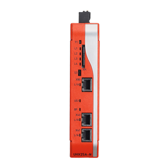
Installation notes Electrical installation 4.2.2 Functional description of the terminals UHX25A-E 24861754123 A: View from top B: View from front Designation Ter- Function minal [1] DC 24 V supply voltage connection DC 24 V voltage supply (2-pin connection) ® PLUS ®/ PLUS [2] EtherCAT /SBus interface EtherCAT... -
Page 21: Voltage Supply
Installation notes Electrical installation Designation Ter- Function minal [6] SD card slot Card slot for SD memory card OMH25A (control section with firmware, IEC program, user data) INFORMATION: Make sure the SD memory card is correctly aligned when inserting it: The name- plate must be on the right side of the SD memory card. - Page 22 Installation notes Electrical installation 4.2.4 Engineering PC connection ® The MOVI-C CONTROLLER is connected to the engineering interface X80 (RJ45 connector) with the engineering PC or other network stations (e.g. visualization sys- tems). The communication is realized via Ethernet. The device is connected to the other network stations, using a category 5, class D twisted-pair cable in accordance with IEC 11801, edition 2.0.
-
Page 23: Ethercat ®/ Sbus Plus Master Connection
Installation notes Electrical installation ®/ PLUS 4.2.5 EtherCAT SBus master connection ® ® PLUS The MOVI-C CONTROLLER serves as EtherCAT /SBus master for the lower- ® PLUS level application inverters (EtherCAT /SBus slaves). The communication takes ® PLUS place via the EtherCAT -based, fast system bus SBus (X30). -
Page 24: Can System Bus Connection
Installation notes Electrical installation Station address ® PLUS EtherCAT /SBus devices from SEW‑EURODRIVE do not have an address that can be set on the device. The devices are detected by their position in the bus struc- ® PLUS ture and are assigned an address by the EtherCAT /SBus master. - Page 25 Installation notes Electrical installation The integrated Ethernet switch The device is equipped with an integrated 2 port Ethernet switch for connecting the fieldbus technology. The following network topologies are supported: • Tree topology • Star topology • Line topology • Ring topology INFORMATION The number of industrial Ethernet switches connected in line impacts the telegram...
-
Page 26: Terminal Assignment
Installation notes Terminal assignment Terminal assignment INFORMATION Reference potentials inside the device: The device internal reference potential is designated as GND in the following table. INFORMATION The assignment "reserved" means that no cable must be connected to this connec- tion. Display Terminal Connection... -
Page 27: Status Leds
Installation notes Status LEDs Status LEDs [10] UHX25A-E 24916378891 A: View from top B: View from front ® PLUS [1] L/A: Status of the EtherCAT /SBus connection [2] L5: Status of the system bus CAN (not yet supported) ® [3] L1: Status of the MOVI‑C CONTROLLER firmware [4] L2: Status of the IEC program [5] L3: Reserved... -
Page 28: Status Led "L1
Installation notes Status LEDs 4.4.1 Status LED "L1" Indicates the status of the firmware during the boot phase as well as during operation. During boot phase Status Possible cause Measure The firmware of the device Contact SEW‑EURODRIVE fails to boot. service. - Page 29 Installation notes Status LEDs Status Possible cause Measure Green The bus electronics is in – standard operating state. Green, flashing The device is waiting for the – Lights up: 0.5 s data of a DHCP server to ini- Disabled: 0.5 s tialize the TCP/IP stack. Red, flashing Conflict detected while assign- Assign an unique IP address...
-
Page 30: Status Led "Ns" (Network Status)
Installation notes Status LEDs 4.4.5 Status LED "NS" (Network Status) Shows the status of the fieldbus connection. Status Possible cause Measure The device does not yet have Assign an unique IP address any IP address parameters. to the device. Green There is a controlling connec- –... -
Page 31: Startup With Ethernet/Ip
Startup with EtherNet/IP™ Industrial Ethernet networks Startup with EtherNet/IP™ Industrial Ethernet networks 5.1.1 TCP/IP addressing and subnetworks The address of the TCP/IP protocol is set using the following parameters: • MAC address • IP address • Subnet mask • Standard gateway The addressing mechanisms and subdivision of the TCP/IP networks into subnet- works are explained in this chapter to help you set the parameters correctly. -
Page 32: Network Class
Startup with EtherNet/IP™ Industrial Ethernet networks 5.1.4 Network class The first byte of the IP address determines the network class and as such represents the division into network addresses and node addresses: Range of Network Example: Complete Meaning values class network address (Byte 1 of IP address) -
Page 33: Standard Gateway
Startup with EtherNet/IP™ Industrial Ethernet networks The class C network with the network address 192.168.10 is further subdivided into the following 2 networks by the subnet mask 255.255.255.128: Network address Node addresses 192.168.10.0 192.168.10.1 – 192.168.10.126 192.168.10.128 192.168.10.129 – 192.168.10.254 The network nodes use a logical AND operation for the IP address and the subnet mask to determine whether there is a communication partner in the same network or in a different network. -
Page 34: Connecting The Movi-Ccontroller To An Ethernet/Ip™ Network
Startup with EtherNet/IP™ Connecting the MOVI‑C® CONTROLLER to an EtherNet/IP™ network Connecting MOVI‑C® C ONTROLLE R to an EtherNet/ IP™ network ® Connecting the MOVI‑C CONTROLLER to an EtherNet/IP™ network ® This examples explains how to connect the MOVI‑C CONTROLLER to an EtherNet/ IP™... -
Page 35: Configuration Of The Ethercat /Sbus Plus Stations
Startup with EtherNet/IP™ Configuration of the EtherCAT®/SBusPLUS stations Configurati on of the EtherCAT®/ SBusPLUS stations ® PLUS Configuration of the EtherCAT /SBus stations ® PLUS In the project example, the following devices are EtherCAT /SBus stations: ® ® PLUS • The MOVI-C CONTROLLER serves as EtherCAT /SBus... - Page 36 Startup with EtherNet/IP™ Configuration of the EtherCAT®/SBusPLUS stations 3. Select the internet protocol version 4 "TCP/IPv4" in the adapter properties. 4. Enter the IP address parameters of the engineering PC in the internet protocol properties. Note that the IP address of the engineering PC is different from the IP address of all other network stations and thus is unique.
-
Page 37: Scanning The Network For Devices
Startup with EtherNet/IP™ Configuration of the EtherCAT®/SBusPLUS stations 5.3.2 Scanning the network for devices Proceed as follows: ® ü The connection between the engineering PC and MOVI-C CONTROLLER is es- tablished. ® 1. Start MOVISUITE ® 2. Create a new MOVISUITE project from a network scan. -
Page 38: Applying Movi-C Devices To Movisuite
Startup with EtherNet/IP™ Configuration of the EtherCAT®/SBusPLUS stations ® ® 5.3.3 Applying MOVI-C devices to MOVISUITE ® The MOVI-C devices are detected during the network scan. Proceed as follows: ü You started a network scan. ® 1. Apply the scanned devices to MOVISUITE 9007216181358219 ®... - Page 39 Startup with EtherNet/IP™ Configuration of the EtherCAT®/SBusPLUS stations ð The function view has 2 views. The tree view shows an overview of the entire project. The circle view shows the current node as a large circle in the center of the working area.
-
Page 40: Configuration Of The Fieldbus Stations
The current version of the device description file for the MOVI‑C CONTROLLER with fieldbus interface EDS file is available on the website of SEW‑EURODRIVE → www.sew-eurodrive.com. Search on the page [Online Support] > [Data & docu- ments] > [Software] for "EDS files for EtherNet/IP™". ®... -
Page 41: Creating A Project In Logix Designer
Startup with EtherNet/IP™ Configuration of the fieldbus stations 5.4.2 Creating a project in Logix Designer Proceed as follows: 1. Start the "Logix Designer" tool. 2. Create a new Logix Designer project. 24488016523 3. Add the PLC to the project. Enter a device name and specify the storage location of the project. -
Page 42: Configuring The Ethernet/Ip™ Scanner
Startup with EtherNet/IP™ Configuration of the fieldbus stations 4. Set the version of the device firmware. 24488508683 ð The project is created. Information about the programs and data in the project is displayed in the "Controller Organizer" (right-hand screen pane). 5.4.3 Configuring the EtherNet/IP™... - Page 43 Startup with EtherNet/IP™ Configuration of the fieldbus stations 2. Select the EtherNet/IP™ scanner. Set a filter to reduce the number of modules shown in the module catalog. 24493778699 ð In this example, there is a filter for "ENB" modules and the EtherNet/IP™ scan- ner "1756-ENBT"...
-
Page 44: Integrating And Configuring The Movi-Ccontroller In The Fieldbus Network
Startup with EtherNet/IP™ Configuration of the fieldbus stations 4. Set the correct firmware version of the EtherNet/IP™ scanner. 5. Enter the IP address of the EtherNet/IP™ scanner. You can find the IP address on the display of the hardware module. 24493782411 ð... - Page 45 Startup with EtherNet/IP™ Configuration of the fieldbus stations 1. Load the device description file to the Studio 5000 Logix Designer. 24496457739 2. Right-click to open the Ethernet interface context menu and add the communica- tion partner. ð A module catalog is displayed. ®...
- Page 46 Startup with EtherNet/IP™ Configuration of the fieldbus stations ® 3. Select the MOVI‑C CONTROLLER. Set a filter to reduce the number of modules shown. 24496493579 ð In this example, there filter "SEW module" ® MOVI‑C CONTROLLER standard UHX25A is the communication partner. ®...
- Page 47 Startup with EtherNet/IP™ Configuration of the fieldbus stations 6. Select the number of process data words that you wish to use for communicating with the subordinated slaves. Set the data format for the process data words. The process data always contain 16 bits (data format INT). 24518069131 ®...
-
Page 48: Setting Up The Project Path
Startup with EtherNet/IP™ Configuration of the fieldbus stations 5.4.5 Setting up the project path A project path is necessary for setting up a connection between the engineering PC and the PLC. Proceed as follows: ® ü You configured the MOVI‑C CONTROLLER. -
Page 49: Loading The Logix Designer Project To The Plc
Startup with EtherNet/IP™ Configuration of the fieldbus stations 5.4.6 Loading the Logix Designer project to the PLC Data (IP address, standard process data) that has been assigned to the fieldbus sta- tions during configuration is first defined only in the Logix Designer project on the engi- neering PC. -
Page 50: Loading The Movisuite
Startup with EtherNet/IP™ Configuration of the fieldbus stations 24519823371 ® ® 5.4.7 Loading the MOVISUITE project to the MOVI-C CONTROLLER ® The fieldbus interface for the slave connection has to be set in the MOVISUITE pro- ® ject and the device configuration has to be loaded to the MOVI‑C CONTROLLER via the IEC Editor. - Page 51 Startup with EtherNet/IP™ Configuration of the fieldbus stations ® 2. Open the configuration of the MOVI‑C CONTROLLER and set the fieldbus pro- tocol. 24542461451 3. Start the IEC Editor with a new project. 18014415436223883 ð A message on the used compiler version is displayed. 4.
- Page 52 Startup with EtherNet/IP™ Configuration of the fieldbus stations 5. To connection from IEC Editor project ® ® MOVI‑C CONTROLLER, double-click on the MOVI‑C CONTROLLER in the device tree and scan the network. Add the found device. 24631452171 ® ð...
- Page 53 Startup with EtherNet/IP™ Configuration of the fieldbus stations ® 6. Build the IEC program in the machine code of the MOVI‑C CONTROLLER. 24631461387 7. After successful compilation of the IEC program, the program can be transferred to ® the MOVI‑C CONTROLLER.
- Page 54 Startup with EtherNet/IP™ Configuration of the fieldbus stations 9. Start the IEC program. 24635518603 ð The MOVI‑C ® CONTROLLER starts. The message "RUN" is displayed in the status bar of the IEC editor. ð The devices in the device tree are marked by a green circle. The green circle indicates fault-free function of the fieldbus interface but does not indicate the ®...
- Page 55 Startup with EtherNet/IP™ Configuration of the fieldbus stations 10. Create a boot project. This way, the IEC Editor project is stored on the SD memory ® card of the MOVI‑C CONTROLLER and is still available after a restart of the ®...
-
Page 56: Controlling The Stations In Test Run
Startup with EtherNet/IP™ Controlling the stations in test run Controlling the stations in test run ® During successful communication between PLC and the MOVI‑C CONTROLLER, process data words are transferred between the devices without faults. ® 5.5.1 Transferring process data words to the MOVI-C CONTROLLER The process data exchange is monitored and controlled in Logix Designer with "Con- troller Tags". - Page 57 Startup with EtherNet/IP™ Controlling the stations in test run 3. Switch to the IEC Editor project. 4. Double click the process data of the EtherNet/IP™ device in the device tree and ® check if the values of the process input data words of the MOVI‑C CONTROLLER are identical to the sent process output data words of the PLC.
-
Page 58: Procedure For Device Replacement
Procedure for device replacement Procedure for device replacement ® When replacing a MOVI-C CONTROLLER, proceed as described in chapter "Installa- notes" (→ 2 18). tion Insert memory card previous ® ® MOVI-C CONTROLLER into the new MOVI-C CONTROLLER. ® The variable values stored permanently on the MOVI-C CONTROLLER are not stored on the SD memory card by default. - Page 59 Service Waste disposal Service Waste disposal Dispose of the product and all parts separately in accordance with their material struc- ture and the national regulations. Put the product through a recycling process or con- tact a specialist waste disposal company. If possible, divide the product into the follow- ing categories: •...
-
Page 60: Technical Data
Technical data Markings Technical data Markings ® The MOVI-C CONTROLLER complies with the following directives and guidelines: Marking Meaning CE mark to state compliance with the following European guidelines: • EMC Directive 2014/30/EU EAC marking (Eurasian Conformity) to certify the conformity with the safety requirements of the Customs Union of Russia, Kazakhstan, and Belarus RCM logo (Regulatory Compliance Mark) to confirm compliance with the technical regulations of the Australian Communications and Media Author-... -
Page 61: General Technical Data
Technical data General technical data General technical data ® MOVI-C CONTROLLER standard UHX25A Interference immunity Meets EN 61800-3, 2. Environment Interference emission Limit value category C2 to EN 61800‑3 Ambient temperature ϑ 0 °C – +60 °C Type of cooling Convection cooling Environmental conditions • Extended storage: EN 60721-3-1 class 1K2 temperature -25 °C to +70 °C •... - Page 62 Technical data Technical data Technical data ® MOVI‑C CONTROLLER standard UHX25A Electrical supply • Power consumption: P = 10 W • Supply voltage V = DC 24 V (-15% / +20%) according to IEC 61131‑2 • Current consumption I = 420 mA (with DC 24 V supply voltage) ®...
-
Page 63: Technical Data Of The Ethernet/Ip™ Interface
Technical data Technical data of the EtherNet/IP™ interface Technical data of the EtherNet/IP™ interface ® MOVI‑C CONTROLLER standard UHX25A Manufacturer ID 013Bhex Product code 17hex Connection technology RJ45 Baud rate 100 MBd/10 MBd (full duplex/half duplex) Maximum process data length 128 PD Application protocols EtherNet/IP™, Modbus TCP, SNMP, DHCP, SEW Application Services Port numbers used... -
Page 64: Port Overview
Technical data Port overview Port overview 8.5.1 Interface description ® The Ethernet interfaces of the MOVI‑C CONTROLLER have the following functions: ® PLUS • X30 – EtherCAT /SBus interface for master connection • X80 – Engineering interface • X40/X41 – Fieldbus interfaces for slave connection 8.5.2 Engineering interface Port... -
Page 65: Dimension Drawing Movi-Ccontroller Standard
Technical data Dimension drawing MOVI-C® CONTROLLER standard Dimension drawing MOVI-C® CONTROLL standard ® Dimension drawing MOVI-C CONTROLLER standard 20566380555 ® Manual – MOVI‑C CONTROLLER standard UHX25A... -
Page 66: Index
Index Index Engineering software........... 17 ® EtherCAT /SBusPLUS Additional documentation ........ 13 Interface ............ 16 Auto-crossing ............ 25 Master port ............. 23 Auto-negotiation .......... 25 Ethernet net Ethernet switch.......... 25 Network topologies......... 25 Checking communication via process data .. 56 Shielding and routing bus cables .... - Page 67 Index Setting for the engineering PC ....... 35 Topology example in the EtherNet/IP™ network ............... 34 ® MOVISUITE ............ 17 LEDs.............. 27 Advantages ............ 17 L/A (Link/Activity).......... 30 ® Applying MOVI-C devices...... 38 L1 .............. 28 Creating a project ........... 37 L2 ..............
- Page 68 Index Signal words in safety notes........ 6 Network class .......... 32 Standard gateway .......... 33 Standard gateway .......... 33 Status LEDs ............ 27 Subnet mask .......... 32 L/A (Link/Activity).......... 30 Technical data ............. 60 L1 .............. 28 Terminals L2 .............. 28 Assignment.............
- Page 72 SEW-EURODRIVE—Driving the world SEW-EURODRIVE GmbH & Co KG Ernst-Blickle-Str. 42 76646 BRUCHSAL GERMANY Tel. +49 7251 75-0 Fax +49 7251 75-1970 sew@sew-eurodrive.com www.sew-eurodrive.com...
Need help?
Do you have a question about the MOVI‑C UHX25A Series and is the answer not in the manual?
Questions and answers