
Related Manuals for SEW-Eurodrive MOVIPRO PHC11A-M1-2A-A1 Series


Summary of Contents for SEW-Eurodrive MOVIPRO PHC11A-M1-2A-A1 Series
- Page 1 *20278543_0914* Drive Technology \ Drive Automation \ System Integration \ Services Operating Instructions Application Controller MOVIPRO ® PHC11A-..M1-..2A-A1/.. Edition 09/2014 20278543/EN...
- Page 2 SEW-EURODRIVE—Driving the world...
-
Page 3: Table Of Contents
Contents Contents General information ........................6 About this documentation ....................6 Structure of the safety notes ..................6 Rights to claim under limited warranty ................7 Exclusion of liability ......................7 Product names and trademarks ..................8 Copyright ........................8 Safety notes .......................... - Page 4 Contents Designation key ......................53 Connection cables ......................54 Cable structure ......................54 X1011: MOVITRANS ® THM20E pick-up ..............55 X1021: MOVITRANS ® THM20C pick-up ..............56 X1201: AC 400 V input ....................57 X2011: Motor with brake control .................. 59 7.10 X2292: Brake control ....................
- Page 5 Contents 11.6 Radio modem ......................102 11.7 Safety technology ....................... 102 11.8 Dimension drawing ..................... 103 Declaration of Conformity ....................104 Address list ..........................105 Index ............................115 ® Operating Instructions – MOVIPRO PHC11A-..M1-..2A-A1/..
-
Page 6: General Information
General information About this documentation General information About this documentation This documentation is an integral part of the product. The documentation is intended for all employees who perform assembly, installation, startup, and service work on the product. Make sure this documentation is accessible and legible. Ensure that persons respon- sible for the system and its operation, as well as persons who work independently on the unit, have read through the entire documentation and understood it. -
Page 7: Rights To Claim Under Limited Warranty
General information Rights to claim under limited warranty Hazard symbol Meaning Warning of dangerous electrical voltage Warning of hot surfaces Warning of risk of crushing Warning of suspended load Warning of automatic restart 1.2.3 Structure of embedded safety notes Embedded safety notes are directly integrated into the instructions just before the de- scription of the dangerous action. -
Page 8: Product Names And Trademarks
General information Product names and trademarks Product names and trademarks The brands and product names in this documentation are trademarks or registered trademarks of their respective titleholders. Copyright © 2014 SEW‑EURODRIVE. All rights reserved. Unauthorized reproduction, modification, distribution or any other use of the whole or any part of this documentation is strictly prohibited. -
Page 9: Safety Notes
Safety notes Preliminary information Safety notes Preliminary information The following basic safety notes must be read carefully to prevent injury to persons and damage to property. The operator must ensure that the basic safety notes are read and observed. Ensure that persons responsible for the machinery and its opera- tion as well as persons who work on the unit independently have read through the documentation carefully and understood it. -
Page 10: Target Group
Safety notes Target group Target group Mechanical work of any kind may be carried out only by trained specialists. Qualified personnel in the context of this documentation are persons who are familiar with the design, mechanical installation, troubleshooting and maintenance of the product and have the following qualifications: •... -
Page 11: Transport
Safety notes Transport Transport Immediately upon delivery, inspect the shipment for any damage that may have occur- red in transit. Inform the shipping company immediately about any damage. You may need to suspend startup. Observe the following notes when transporting the unit: •... -
Page 12: Electrical Connection
Safety notes Electrical connection Electrical connection Observe applicable national accident prevention regulations when working on a live unit. Perform electrical installation according to the pertinent regulations (e.g. cable cross sections, fusing, protective conductor connection). The documentation contains addi- tional notes. Preventive measures and protection devices must meet the applicable regulations (e.g. -
Page 13: Inspection/Maintenance
Safety notes Inspection/maintenance Where required, systems in which such units are installed must be equipped with addi- tional monitoring and protection devices in accordance with the respective applicable safety regulations, e.g. the law governing technical equipment, accident prevention regulations, etc. Additional protective measures may be necessary for applications with increased po- tential risk. -
Page 14: Unit Structure
Unit structure Type designation Unit structure Type designation The type designation comprises the following characteristic data: Product range: P = MOVIPRO ® Control type: H = Application controller Housing type: C = Modular Housing depth: 1 = 70 mm Housing height: 1 = 300 mm Version Supply:... -
Page 15: Scope Of Delivery
Unit structure Scope of delivery 001 Option: 001 = Operating switch Scope of delivery The following components are included in the delivery: ® • MOVIPRO PHC11A-..M1-..2A-A1/.. • Grounding kit Short designations The following short designations are used: Type designation Supply Short designa- Power tion... -
Page 16: Unit Overview
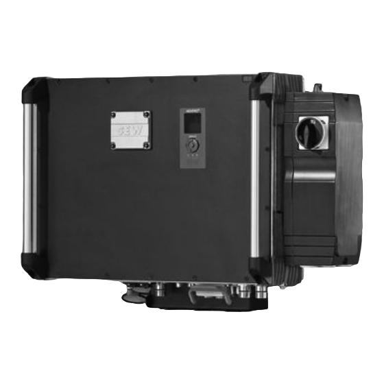
Unit structure Unit overview Unit overview The following figure gives an overview of the main parts of the unit and the location of the identifiers: 9007202514559883 Main nameplate Function unit nameplate Status display Cooling fins T-slot profile Terminal strip Service interface Connection block label ®... -
Page 17: Identification
Unit structure Identification Identification 3.5.1 Main nameplate The following figure shows an example of a nameplate: Type: PH.. SO#: XXX.XXXXXXXX.XXX.XX Part#: Eingang / Input Ausgang / Output D-76646 Bruchsal Made in Germany MOVIPRO IPXX Product-Key: 36028798225065995 The main nameplate lists the following information: •... - Page 18 Unit structure Identification 3.5.2 Function modules nameplate This nameplate describes the unit's internal function modules. The following figure shows an example of a nameplate for the function modules: Product-Key: XXX.XXXXXXXX.XXX.XX Funktionsbaugruppen/function units PFH-.. PFF-.. PFA-.. PFS-.. PFE-.. PFZ-.. 18014401506207371 Designation Function PFA-..
- Page 19 Unit structure Identification Power section ® MOVIPRO product range Internal function Internal axis MD Frequency inverter on MOVIDRIVE ® basis Frequency inverter power rating: 022 = 2.2 kW 040 = 4.0 kW Generation B Encoder evaluation Motor encoder type: 0 = Without motor encoder Distance encoder type: 0 = Without distance encoder Brake control...
- Page 20 Unit structure Identification Communication and control unit ® MOVIPRO product range Internal function Control and communication E4 = LAN, TCP + UDP W4 = WLAN, TCP + UDP SEWOS function level Version 1 ID module storage medium Standard ID module with M12 connector Fieldbus interface 00 = No bus connection 83 = 1 x Ethernet M12, copper...
- Page 21 Unit structure Identification Power supply ® MOVIPRO product range Internal function Power supply Supply type: AC = Power supply ® TR = MOVITRANS Rated input power: 016 = 1.6 kW 020 = 2.0 kW 040 = 4.0 kW 080 = 8.0 kW Version A Unit supply: 001 = Connection for plug connectors...
-
Page 22: Accessories
Unit structure Accessories 3.5.3 Connection block label The following figure shows an example of a connection block label: MAC DLC XY:YX:ZX:X XY:YX:YZ:X MAC WLAN Type: PH.. MAC DLC ##:##:##:##:##:## SO#: XXX.XXXXXXXX.XXX.XX MAC WLAN ##:##:##:##:##:## 45036001100885771 MAC address of processing unit MAC address of radio modem The connection block sticker lists the following information depending on the unit con- figuration:... - Page 23 Unit structure Accessories 3.6.2 Optional connector Part number Jumper plug 11747099 ID module 17974186 For additional information, refer to the addendum to the operating instructions ® “MOVIPRO – Accessories”. 3.6.3 Sensor/actuator boxes Designation Part number Sensor/actuator box 1.0 m 13309269 Sensor/actuator box 2.0 m 13309277 Sensor/actuator box 3.0 m...
-
Page 24: Function Modules
Unit structure Function modules Function modules 3.7.1 Internal axis PFA.. The function module consists of the following internal elements. ® Drive inverter with MOVIDRIVE platform The frequency inverter on a MOVIDRIVE ® basis is use to control asynchronous mo- tors. For detailed information about motor assignment and system properties, refer to the "MOVIDRIVE ®... - Page 25 Unit structure Function modules The S1 operating switch disconnects the motor phases (U, V, W) at the unit's output and sets the controller inhibit of the inverter via auxiliary contact. 9007199587528075 Operating switch ® Operating Instructions – MOVIPRO PHC11A-..M1-..2A-A1/..
- Page 26 Unit structure Function modules 3.7.2 PFH.. communication and control unit The function module consists of the following internal elements. Fieldbus interface Depending on the design, the unit offers one of the following communication options: Communication Function module LAN, TCP / UDP PFH-E4..
- Page 27 Unit structure Function modules Service unit The service unit is used for startup, diagnostics, and maintenance of the unit. It is equipped with a status display and a service interface 54043196587315339 Status display, infrared interface Service interface Status display The status display is used to display status messages and in this way allows for quick- ly evaluating the current status of the application software.
- Page 28 Unit structure Function modules 3.7.3 PFE... power supply 24 V power supply unit for internal components The unit is equipped with an integrated power supply unit that uses the DC link voltage to generate a DC 24 V supply for internal components. 24 V power supply unit for external supply An integrated power supply unit uses the DC link voltage to generate a DC 24 V sup- ply for externally connected components.
-
Page 29: Integrated Safety Technology
Integrated safety technology Standards Integrated safety technology WARNING Failure of the safety components because of incorrect startup. Severe or fatal injuries. • Only use the unit in combination with functional safety technology when you have ® the “MOVIPRO – Functional Safety” manual at hand and you ensure compli- ance with the requirements for operation with functional safety. -
Page 30: Mechanical Installation
Mechanical installation Requirements Mechanical installation Requirements WARNING Risk of crushing if the load falls. Severe or fatal injuries. • Do not sit or stand underneath the load. • Secure the area in which the mechanical installation is to take place. NOTICE Risk of collision. - Page 31 Mechanical installation Requirements 5.1.1 Mounting position The mounting position for units with cooling fins depends on the application: Applica- Mounting po- Speed Power reduction tion sition Stationary Vertical [1] Horizontal [2] Mobile Vertical [1] Slow traveling velocity ≤ 0.5 m/s Horizontal [2] Vertical [1] Fast traveling velocity >...
- Page 32 Mechanical installation Requirements 5.1.2 Minimum clearance INFORMATION • Observe the required minimum clearance for: – The connection of the cables and plug connectors – Handling of the display, diagnostics and operating elements – Heat convection at the level of the cooling fins, if installed •...
- Page 33 Mechanical installation Requirements Clearance Function Size F: On the side (optional) Space for connection cables, plug connec- See dimension drawing tors, add-on elements and elements for op- eration, e.g. maintenance switch Horizontal installation The following figure shows the required minimum clearance sizes of the unit: 36028797483068939 Housing cover clearance Clearance on the side...
-
Page 34: Assembly
Mechanical installation Assembly 5.1.3 Waste heat Ensure that the cooling fins can dissipate waste heat into the environment by free con- vection. Observe the following notes to ensure optimum heat convection: • Use SEW mounting systems or suitable spacers, e.g.: –... - Page 35 Mechanical installation Assembly 63050395199050507 Unit M5 × 8 studs Large mounting bracket Bore for M8 screw of suitable length with washer Bore for M5 × 8 stud Bore for M8 × 30 screw T-slot Bore for M6 screw of suitable length with washer Holding fixture, e.g.
- Page 36 Mechanical installation Assembly The following figure shows the required dimensions: 86.5 (3.41) Ø15 (0.59) Ø 6.6 (0.26) 14.6 (0.575) 40.5 66 (2.6) 20 (0.79) (1.59) 114.5 (4.508) 9686885899 X, Y Housing dimensions, see chapter “Technical data” Bore dimension Distance Procedure 1.
- Page 37 Mechanical installation Assembly Mounting the unit 1. Use the mounting brackets to hang the unit on the fixture. 2. Securely fasten the mounting bracket via the bores on the holding fixture using M6 screws. 9797753867 5.2.2 Mounting using the through bores CAUTION Risk of injury due to protruding parts.
- Page 38 Mechanical installation Assembly The following figure shows the design of the through bore and the minimum clearance in mm (in): 9 (0.4) 6.5 (0.26) 9 (0.4) 36028797483065611 Unit Cooling fins Height of the through bore + T-slot (see the dimension drawing in chapter “Technical data”...
- Page 39 Mechanical installation Assembly 36028797493776523 Mounting elements, e.g. M6 screws Locking elements, e.g. lock washers Mounting elements, e.g. washers Mounting surface, e.g. mounting plate X, Y Housing dimensions Bore dimensions Procedure 1. Refer to the dimension drawing in chapter “Technical data” for the housing dimen- sions X and Y.
- Page 40 Mechanical installation Assembly – Suitable spacers – Mounting plate (with an appropriate cut-out for long cooling fins) • Suitable mounting and safety elements, e.g. M8 screws of an appropriate length with washers • Suitable locking devices, e.g. lock washers 18014398973593739 Mounting elements, e.g.
- Page 41 Mechanical installation Assembly Bore di- Value mension Housing dimension Y − 30 mm (1.2 in), see the following dimension drawing 3. Mark the tapped holes on the mounting surface [4]. 4. Drill the bores at the marked points. 5. Firmly screw the unit on the mounting surface [4] from the back via the through bores.
-
Page 42: Electrical Installation
Electrical installation Protective measures against electrical hazards Electrical installation Protective measures against electrical hazards 6.1.1 Overview The following figure is an overview of the preventive measures against electrical haz- ards: Protective measures according to IEC 60364-4-43 Mobile application Stationary application Direct Direct Contactless Energy... - Page 43 Electrical installation Protective measures against electrical hazards • Supply system lead 16 mm - 35 mm (AWG 6 – AWG 2): Route a copper protective earth conductor with a cable cross section of 16 mm • Supply system cable > 35 mm (AWG 2): Route a copper protective earth conductor with half the cross section of the supply cable.
- Page 44 Electrical installation Protective measures against electrical hazards Contactless energy transfer ® The following preventive measures protect mobile systems with MOVITRANS con- tactless energy transfer systems against electrical hazards: • Protective separation • ESD protection Protective separation Compliance with "preventive separation" in line with VDE 0100 part 410 nominal volt- age ≤...
- Page 45 Electrical installation Protective measures against electrical hazards Dissipation of electrical charges between vehicle support frames (vehicle mass) and a ground potential (ESD protection) is permitted. ® Grounding mobile MOVITRANS systems in zones with a protective grounding meas- ure does not cause an increased risk potential and is consequently permitted. Additional informa- The insulation capacity of the equipment and the effectiveness of the equipotential tion for operation...
- Page 46 Electrical installation Protective measures against electrical hazards 6.1.4 Unit connection points for grounding or equipotential bonding The connection points for grounding or equipotential bonding are marked on the hous- ing corners of the units with the symbol y. The bores in the housing corners are prepared for M5 self-tapping screws, for exam- ple M5 x 12 according to DIN ISO 3506 or equivalent.
-
Page 47: Line Connection Energy Supply
Electrical installation Line connection energy supply 6.1.5 Fuses and residual current devices WARNING Risk of injury due to use of the wrong earth-leakage circuit breaker (ELCB). Severe or fatal injuries. • The unit can cause direct current in the protective earth. If you are using a resid- ual current device (RCD) for protection against direct or indirect contact, only an RCD of type B on the current supply side of the unit is permitted. - Page 48 Electrical installation Line connection energy supply 6.2.3 Contactors Only use contactors in utilization category AC-3 (EN 60947-4-1) as line and brake contactors. 6.2.4 Electromagnetic compatibility (EMC) INFORMATION The unit can cause EMC interference within the permitted limit range according to DIN EN 61800-3.
- Page 49 Electrical installation Line connection energy supply 6.2.7 Shielding Required material Use shielded power supply and electronics cables. 1. Connect the shield and make sure it is grounded over a wide area at both ends. 2. For cables with multiple shields, also connect the inner shield at both ends making sure it is grounded over a wide area.
- Page 50 Electrical installation Line connection energy supply 6.2.9 Braking resistor WARNING Danger of electric shock due to high DC voltage in the supply lines (about DC 900 V). Severe or fatal injuries. • Only use cables provided by SEW-EURODRIVE. • Install the cables according to the instructions. WARNING Burns caused by hot surfaces.
-
Page 51: Movitrans ® Energy Supply
Electrical installation MOVITRANS® energy supply • Thermal properties (e.g. temperature stability, heating of the unit, flammability class) • EMC behavior (such as interference emission limit values, compliance with interfer- ence immunity values stipulated in standards) • Functional safety (approvals according to EN ISO 13849-1) Non-SEW cables not explicitly recommended by SEW‑EURODRIVE must meet at least the requirements of the following standards and have been permitted according to these standards:... -
Page 52: Electrical Connections
Electrical connections Terminal strip Electrical connections Terminal strip WARNING Risk of electric shock due to connecting or disconnecting plug connectors when volt- age is applied. Severe or fatal injuries. • Disconnect all supply voltages. • Make sure that the unit is de-energized. •... -
Page 53: Representation Of Connections
Electrical connections Representation of connections • Brake control • Communication package You can find more information on the function modules in chapter "Function modules nameplate" (→ 2 18). Representation of connections The following wiring diagrams show the contact end of the connections. Designation key The designations of the connections are based on the following structure: Xabbc_mn. -
Page 54: Connection Cables
Electrical connections Connection cables Connection cables Connection cables are not included in the delivery. Prefabricated cables for connection between SEW components can be ordered from SEW-EURODRIVE. For each connection, the available prefabricated cables are listed. Specify the part number and length of the required cable in your order. The number and design of the required connection cables depend on the unit variant and the components to be connected. -
Page 55: X1011: Movitrans Thm20E Pick-Up
Electrical connections X1011: MOVITRANS THM20E pick-up 7.5.2 Examples The following examples illustrate the cable structure: • 3G1.5: Cable with 3 cores of 1.5 mm each, one green-yellow cable • ((2X2X0.25)+4G2.5): Shielded hybrid cable with – 4 twisted-pair cables of 0.25 mm each, shielded, and –... -
Page 56: X1021: Movitrans Thm20C Pick-Up
Electrical connections X1021: MOVITRANS THM20C pick-up X1021: MOVITRAN S THM20C pick-up X1021: MOVITRANS ® THM20C pick-up The following table displays information about this connection: Function Unit supply with MOVITRANS ® THM20C pick-up Connection type ® Q 4/2, female Wiring diagram 9007201698869771 Assignment Name... -
Page 57: X1201: Ac 400 V Input
Electrical connections X1201: AC 400 V input X1201: AC 400 V input The following table shows information about this connection: Function AC 400 V input to supply units up to 16.0 kW Connection type ® Q 4/2, male Wiring diagram 4 PE 2444131083 Assignment... - Page 58 Electrical connections X1201: AC 400 V input Cable Length / Component Installation type Part number: 11745614 Cable design: (4G4) Variable length – ® Q 4/2 ↔ open with conductor end sleeves Part number: 18150306 Cable design: (4G2.5) Variable length – ®...
-
Page 59: X2011: Motor With Brake Control
Electrical connections X2011: Motor with brake control X2011: Motor with brake control NOTICE Damage or malfunction due to motors with built-in brake rectifiers. Damage to the drive system or its environment. • You must not use motors with built-in brake rectifiers in conjunction with ®... - Page 60 Electrical connections X2011: Motor with brake control 7.9.1 Connection cables The following table shows the cables available for this connection. The cables are ap- proved up to 2.2 kW according to IEC / UL. Cable Length/ Component Installation type Part number: 18125794 DRS71 –...
- Page 61 Electrical connections X2011: Motor with brake control Cable Length/ Component Installation type Part number: 18125859 CMP63 – 80 Variable length ® Q 8/0 ↔ SB11 Conductor assignment The following tables shows the conductor assignment in cables with the following part number and the corresponding motor terminals of the motor: 18125794 Motor terminal...
- Page 62 Electrical connections X2011: Motor with brake control The following figure shows the connection of the hybrid cable to the terminal box of the motor. However, also observe the wiring diagram of the respective motor. GNYE BK/W1 BK/V1 BK/U1 BK/3 BK/1 BK/2 BK/4 BK/5...
-
Page 63: X2292: Brake Control
Electrical connections X2292: Brake control 7.10 X2292: Brake control The following table shows information about this connection: Function Connection for SEW brake Connection type M12, 5-pole, female, A-coded Wiring diagram 9007201519557259 Assignment Name Function res. Reserved SEW brake terminal 14 (white) SEW brake terminal 15 (blue) SEW brake terminal 13 (red) res. -
Page 64: X2301: Braking Resistor
Electrical connections X2301: Braking resistor 7.11 X2301: Braking resistor The following table shows information about this connection: Function Power connection for external braking resistor Connection type ® Q 5/0, female Wiring diagram Assignment Name Function n.c. Not connected n.c. Not connected Braking resistor (+) n.c. - Page 65 Electrical connections X2301: Braking resistor Conductor assignment The following table shows the conductor assignment of the cable with part number 11722916: Signal name Color coding Black / 1 Black / 2 PE connection Green/yellow ® Operating Instructions – MOVIPRO PHC11A-..M1-..2A-A1/..
-
Page 66: X2311: Dc 24 V Output
Electrical connections X2311: DC 24 V output 7.12 X2311: DC 24 V output The following table displays information about this connection: Function DC 24 V output to supply external components Connection type ® Q 5/0, female Wiring diagram Assignment Name Function +24V DC 24 V output... -
Page 67: X2551: Dc 24 V Output For 2 Voltage Potentials
Electrical connections X2551: DC 24 V output for 2 voltage potentials 7.13 X2551: DC 24 V output for 2 voltage potentials The following table displays information about this connection: Function DC 24 V output for 2 voltage potentials Connection type ®... - Page 68 Electrical connections X2551: DC 24 V output for 2 voltage potentials 7.13.1 Connection cables The following table shows the available cable for this connection: Connection cable and component Encoder cable Length / Installation type Part number 1 814 307 5 Variable length Cable design: 7G1.5 ®...
-
Page 69: X4001: Rs485 Interface - System Bus
Electrical connections X4001: RS485 interface – system bus 7.14 X4001: RS485 interface – system bus The following table displays information about this connection: Function Internal RS485 interface (system bus) Connection type M12, 5-pole, female, B-coded Wiring diagram 9007201609172107 Assignment Name Function +24V DC 24 V output... -
Page 70: X4011: Rs485 Interface - External
Electrical connections X4011: RS485 interface – external 7.15 X4011: RS485 interface – external The following table shows information about this connection: Function RS485 interface for external components Connection type M12, 5-pole, female, B-coded Wiring diagram 9007201609172107 Assignment Name Function +24V DC 24 V output RS485 data line (-) Reference potential... -
Page 71: X4101: Can Bus - System Bus
Electrical connections X4101: CAN bus – system bus 7.16 X4101: CAN bus – system bus The following table shows information about this connection: Function Internal CAN bus (system bus) – output Connection type M12, 5-pole, female, A-coded Wiring diagram 9007201519557259 Assignment Name Function... - Page 72 Electrical connections X4101: CAN bus – system bus Cable Length / Installation type Length: 5 m, part number: 13281402 Length: 10 m, part number: 13281410 Length: 15 m, part number: 13281429 Cable design: ((1X2X0.2)+(1X2X0.32)+1X0.32) Fixed length M12, male, A‑coded ↔ open with conductor end sleeves Conductor assignment The following table shows the conductor assignment of cables with the following part numbers:...
-
Page 73: X4111: Can Bus - External
Electrical connections X4111: CAN bus – external 7.17 X4111: CAN bus – external The following table shows information about this connection: Function CAN bus for external components Connection type M12, 5-pole, female, A-coded Wiring diagram 9007201519557259 Assignment Name Function CAN_SHLD Shield/equipotential bonding +24V DC 24 V output... - Page 74 Electrical connections X4111: CAN bus – external Cable Length/ Component Installation type Length: 5 m, part number: 13281402 Length: 10 m, part number: 13281410 Length: 15 m, part number: 13281429 Cable design: ((1X2X0.2)+(1X2X0.32)+1X0.32) fixed length – M12 ↔ open with conductor end sleeves Conductor assignment The following table shows the conductor assignment of cables with the following part numbers:...
-
Page 75: X4211: Wlan Antenna (Main)
Electrical connections X4211: WLAN antenna (main) 7.18 X4211: WLAN antenna (main) The following table shows information about this connection: Function Antenna connection for WLAN communication, parameterizable for send and receive functions Connection type R-TNC socket Wiring diagram 36028797359150475 Assignment Name Function inner conductor Inner conductor outer conductor Outer conductor... -
Page 76: X4223: Ethernet Service Interface
Electrical connections X4223: Ethernet service interface 7.19 X4223: Ethernet service interface The following table shows information about this connection: Function Ethernet service interface of the communication and control unit Connection type Ethernet-RJ45 Wiring diagram 9007201609174667 Assignment Name Function Transmit line (+) Transmit line (-) Receive line (+) res. -
Page 77: X4233: Ethernet Fieldbus
Electrical connections X4233: Ethernet fieldbus 7.20 X4233: Ethernet fieldbus The following table shows information about this connection: Function Ethernet fieldbus interface, 4-pole Connection type M12, 4-pole, female, D-coded Wiring diagram 9007201719341963 Assignment Name Function Transmit line (+) Receive line (+) Transmit line (-) Receive line (-) ®... -
Page 78: X4261: Wlan Antenna (Aux)
Electrical connections X4261: WLAN antenna (aux) 7.21 X4261: WLAN antenna (aux) The following table shows information about this connection: Function Antenna connection for WLAN communication, parameterizable for send and receive functions Connection type R-TNC socket Wiring diagram 36028797359150475 Assignment Name Function inner conductor Inner conductor outer conductor Outer conductor... -
Page 79: X4401: Id Module
Electrical connections X4401: ID module 7.22 X4401: ID module The following table shows information about this connection: Function Interface for ID module from SEW‑EURODRIVE Connection type M12, 5-pole, male, A-coded Wiring diagram 9007201519559179 Assignment Name Function Reference potential IDM-Data ID module data line res. -
Page 80: X5001_1: Digital Inputs/Outputs
Electrical connections X5001_1: Digital inputs/outputs 7.23 X5001_1: Digital inputs/outputs The following table shows information about this connection: Function Digital inputs/outputs of the communication and control unit Connection type M23, P insert, 12-pole, female, 0°-coded Wiring diagram 2264820107 Assignment Name Function DI0.0 Digital input DI0.0 DI0.1... -
Page 81: X5001_2: Digital Inputs/Outputs
Electrical connections X5001_2: Digital inputs/outputs 7.24 X5001_2: Digital inputs/outputs The following table shows information about this connection: Function Digital inputs/outputs of the communication and control unit Connection type M23, P insert, 12-pole, female, 0°-coded Wiring diagram 2264820107 Assignment Name Function DI1.0 Digital input DI1.0 DI1.1... -
Page 82: X5502: Safe Disconnection - Input
Electrical connections X5502: Safe disconnection – input 7.25 X5502: Safe disconnection – input WARNING Risk of injury due to non-safety-related disconnection of the unit if the connection is jumpered Severe or fatal injuries • Jumper this connection only if the unit will not perform any safety functions ac- cording to EN ISO 13849-1. - Page 83 Electrical connections X5502: Safe disconnection – input 7.25.1 Connection component The following component is suitable for this connection: Jumper plug Part number 11747099 Structure: bridged 1+4 / 2+3 Connection: M12 63050395932099851 ® Operating Instructions – MOVIPRO PHC11A-..M1-..2A-A1/..
-
Page 84: Startup
Startup General information Startup General information INFORMATION Observe the general safety notes in chapter "Safety notes / General information". WARNING Risk of injury due to uncontrolled unit behavior caused by ineffective emergency stop circuit. Severe or fatal injuries. • The installation must be carried out by qualified personnel only. WARNING Risk of injury due to unit malfunction caused by incorrect unit setting. -
Page 85: Prerequisites
Startup Prerequisites NOTICE Danger due to arcing. Damage to electrical components. • Do not plug or unplug the power connectors during operation. INFORMATION To ensure fault-free operation, do not disconnect or connect signal lines during oper- ation. Prerequisites The following conditions apply to the startup: •... -
Page 86: Device Configuration
Startup Device configuration Device configuration 8.4.1 Settings During startup, the different components of the unit are configured, parameterized and/or installed: • Configuration of the radio modem settings • Configuration of the processing unit • Parameterization of the frequency inverter Use the X4223 (Ethernet service interface of the communication and control unit) to establish the connection to the processing unit of the unit. -
Page 87: Main Axes
Startup Main axes 8.4.3 Additional Information For additional information, refer to the following documentation: ® • "MOVIVISION Parameter and Diagnostics Tool" manual • "MOVIVISION ® - MOVIPRO ® Software Interface" manual ® • "MOVIDRIVE MDX60B/61B" system manual Main axes The unit is delivered with the following main axis addresses: Position m of the plug connector designation is relevant for the SBus address of the respective axis. -
Page 88: Operation
Operation Control of the brake modules Operation WARNING When the unit is switched on, dangerous voltages are present at the connectors and at any connected cables and motor terminals. This also applies even when the fre- quency inverter of the unit is inhibited and the motor is at standstill. Severe or fatal injuries from electric shock •... -
Page 89: Cyclic Duration Factor (Cdf)
Operation Cyclic duration factor (CDF) INFORMATION • For operating modes with encoder feedback, parameters must not be changed in cycles faster than 2 seconds. This ensures that the encoders are initialized. • The maximum output frequency in the VFC operating modes without encoder feedback is 150 Hz. -
Page 90: Operating The Brake Control
Operation Operating the brake control 9.2.3 Duty type S2 Short-time duty: Operation at constant load for a limited, given time followed by a time at rest. The motor returns to ambient temperature during the rest period. P, ϑ ϑ ϑ 2325835787 9.2.4 Duty type S3... -
Page 91: Status Reports
Operation Status reports 9.3.1 Brake control under normal operating conditions, e.g. automatic operation of the plant With a brake coil power of P ≥ 70 W, you must ensure a timeout of at least 1 second for brake control: Brake t on t on t on... -
Page 92: Service
Service Line connection energy supply Service 10.1 Line connection energy supply 10.1.1 Inspection/maintenance The unit is maintenance-free. SEW-EURODRIVE does not stipulate any regular in- spection work. However, it is recommended that you check the following parts regular- • Connection cables: Damaged or fatigued cables must be replaced immediately. - Page 93 Service Line connection energy supply Replacing the unit Proceed as follows to replace the unit: 1. Disconnect the unit and remove it from the system. 2. Loosen the connection of the ID module and remove it from the X4401. 3. Plug the ID module into connection X4401 of a new unit and tighten the screw. 4.
- Page 94 Service Line connection energy supply Fault memory The fault memory (P080) stores the last 5 error messages (faults t-0 through t-4) of the frequency inverter. The oldest error message is deleted whenever more than five error messages have occurred. The following information is stored when a fault occurs: •...
- Page 95 Service Line connection energy supply Reset WARNING Danger due to unintended motor startup. Severe or fatal injuries. • Comply with the startup instructions. • Set the controller inhibit. • Switch off the output stage. • Decouple the drive. • Deactivate the auto-reset function for drives that start up automatically. An error message can be acknowledged by: •...
- Page 96 Service Line connection energy supply 10.1.7 Extended storage If the unit is stored for a long time, connect it to the power supply for at least 5 minutes every 2 years. Otherwise, the unit's service life may be reduced. Procedure when maintenance has been neglected: Electrolytic capacitors are used in the frequency inverters.
-
Page 97: Movitrans ® Energy Supply
Service MOVITRANS® energy supply MOVITRAN S® energy supply 10.2 MOVITRANS ® energy supply Also observe the information in the following chapters: • Inspection/maintenance (→ 2 92) • Unit replacement (→ 2 92) • Display (→ 2 93) • Fault information of the frequency inverter (→ 2 93) •... -
Page 98: Technical Data
Technical data Basic unit Technical data 11.1 Basic unit General information Rated input power 2.2 kW/4.0 kW 1.6 kW 2.0 kW 2.2 kW/4.0 kW Supply type AC three-phase MOVITRANS ® current Weight 17 kg (37 lb) 17 kg (37 lb) 18 kg (40 lb) Weight with optional 18 kg (40 lb) -
Page 99: Axis Data
Technical data Axis data Output data Rated input power 2.2 kW/4.0 kW 1.6 kW 2.0 kW 2.2 kW/4.0 kW ® Supply type AC three-phase MOVITRANS current Rated output power 2.2 kW (3.0 HP) 1.6 kW (2.1 HP) 2.0 kW (2.7 HP) 2.2 kW (3.0 HP) Operating mode S1 (IEC 60034‑1) -
Page 100: Brake Control
Technical data Brake control 11.3 Brake control Function module PFA-..S23-.. PFA-..S40-.. PFA-..S46-.. Terminal designation X2011 Brake voltage DC 96 V DC 167 V DC 190 V SEW brake type AC 230 V AC 400 V AC 460 V Nominal brake current DC 1.2 A DC 0.7 A DC 0.6 A... -
Page 101: Processing Unit
Technical data Processing unit 11.5 Processing unit General information Type Micro Dynamic Logic Controller (Micro DLC) Engineering Engineering is performed via the Ethernet service interface and the Chip- tool PC software or MOVIVISION ® Digital inputs Compatibility PLC-compatible according to IEC 61131-2:2008-04 “Standard operating ranges for digital inputs (current sinking)”... -
Page 102: Radio Modem
Technical data Radio modem 11.6 Radio modem For more information, technical data and approvals, refer to the latest edition of the addendum to the "MOVIPRO ® Drive and Application Controller – REC5 Radio Mo- dem" operating instructions. 11.7 Safety technology 11.7.1 General Safety characteristics... -
Page 103: Dimension Drawing
Technical data Dimension drawing 11.8 Dimension drawing The dimension drawing shows the mechanical dimensions of the unit in mm (in): 602 (23.7) 570 (22.44) 540 (21.26) 254.8 (10.04) M8x25 (4x) 6.5 (0.26) 5428441099 ® Operating Instructions – MOVIPRO PHC11A-..M1-..2A-A1/.. -
Page 104: Declaration Of Conformity
Dimension drawing Declaration of Conformity EC Declaration of Conformity Translation of the original text 900330014 SEW EURODRIVE GmbH & Co KG Ernst-Blickle-Straße 42, D-76646 Bruchsal declares under sole responsibility that the following products Drive systems of the series PHC11A-..M1-..2A-A1/.. (18255493) -
Page 105: Address List
Address list Address list Germany Headquarters Bruchsal SEW-EURODRIVE GmbH & Co KG Tel. +49 7251 75-0 Production Ernst-Blickle-Straße 42 Fax +49 7251 75-1970 Sales D-76646 Bruchsal http://www.sew-eurodrive.de P.O. Box sew@sew-eurodrive.de Postfach 3023 • D-76642 Bruchsal Production / Industri- Bruchsal SEW-EURODRIVE GmbH & Co KG Tel. - Page 106 Address list Argentina Assembly Buenos Aires SEW EURODRIVE ARGENTINA S.A. Tel. +54 3327 4572-84 Sales Ruta Panamericana Km 37.5, Lote 35 Fax +54 3327 4572-21 (B1619IEA) Centro Industrial Garín sewar@sew-eurodrive.com.ar Prov. de Buenos Aires http://www.sew-eurodrive.com.ar Australia Assembly Melbourne SEW-EURODRIVE PTY. LTD.
- Page 107 Address list Canada Assembly Toronto SEW-EURODRIVE CO. OF CANADA LTD. Tel. +1 905 791-1553 Sales 210 Walker Drive Fax +1 905 791-2999 Service Bramalea, ON L6T 3W1 http://www.sew-eurodrive.ca l.watson@sew-eurodrive.ca Vancouver SEW-EURODRIVE CO. OF CANADA LTD. Tel. +1 604 946-5535 Tilbury Industrial Park Fax +1 604 946-2513 7188 Honeyman Street b.wake@sew-eurodrive.ca...
- Page 108 Address list Czech Republic Drive Service Hot- HOT-LINE +420 800 739 739 (800 SEW SEW) Servis: line / 24 Hour Tel. +420 255 709 632 Service Fax +420 235 358 218 servis@sew-eurodrive.cz Denmark Assembly Copenhagen SEW-EURODRIVEA/S Tel. +45 43 9585-00 Sales Geminivej 28-30 Fax +45 43 9585-09...
- Page 109 Address list India Registered Office Vadodara SEW-EURODRIVE India Private Limited Tel. +91 265 3045200, +91 265 2831086 Assembly Plot No. 4, GIDC Fax +91 265 3045300, +91 265 2831087 Sales POR Ramangamdi • Vadodara - 391 243 http://www.seweurodriveindia.com Service Gujarat salesvadodara@seweurodriveindia.com Assembly Chennai...
- Page 110 Address list Lebanon Sales Jordan / Ku- Beirut Middle East Drives S.A.L. (offshore) Tel. +961 1 494 786 wait / Saudi Arabia / Sin El Fil. Fax +961 1 494 971 Syria B. P. 55-378 info@medrives.com Beirut http://www.medrives.com After Sales Service service@medrives.com Lithuania Sales...
- Page 111 Address list New Zealand Assembly Auckland SEW-EURODRIVE NEW ZEALAND LTD. Tel. +64 9 2745627 Sales P.O. Box 58-428 Fax +64 9 2740165 Service 82 Greenmount drive http://www.sew-eurodrive.co.nz East Tamaki Auckland sales@sew-eurodrive.co.nz Christchurch SEW-EURODRIVE NEW ZEALAND LTD. Tel. +64 3 384-6251 10 Settlers Crescent, Ferrymead Fax +64 3 384-6455 Christchurch...
- Page 112 Address list Senegal Sales Dakar SENEMECA Tel. +221 338 494 770 Mécanique Générale Fax +221 338 494 771 Km 8, Route de Rufisque senemeca@sentoo.sn B.P. 3251, Dakar http://www.senemeca.com Serbia Sales Beograd DIPAR d.o.o. Tel. +381 11 347 3244 / +381 11 288 Ustanicka 128a 0393 PC Košum, IV sprat...
- Page 113 Address list South Korea Assembly Ansan SEW-EURODRIVE KOREA CO., LTD. Tel. +82 31 492-8051 Sales B 601-4, Banweol Industrial Estate Fax +82 31 492-8056 Service #1048-4, Shingil-Dong, Danwon-Gu, http://www.sew-korea.co.kr Ansan-City, Kyunggi-Do Zip 425-839 master.korea@sew-eurodrive.com Busan SEW-EURODRIVE KOREA Co., Ltd. Tel. +82 51 832-0204 No.
- Page 114 Address list Production Southeast Region SEW-EURODRIVE INC. Tel. +1 864 439-7537 Assembly 1295 Old Spartanburg Highway Fax Sales +1 864 439-7830 Sales P.O. Box 518 Fax Manufacturing +1 864 439-9948 Service Lyman, S.C. 29365 Fax Assembly +1 864 439-0566 Fax Confidential/HR +1 864 949-5557 http://www.seweurodrive.com cslyman@seweurodrive.com Assembly...
-
Page 115: Index
Index Index Numerical Processing unit ..........26 Service unit ............. 27 24 V output, see DC 24 V output ......66 TPM30 mobile converter......... 28 24 V brake control ..........24 Configuration 400 V input, see AC 400 V input ......57 Software............ - Page 116 Index Digital I/O control unit Functional safety technology Connection............81 Applicable standards........29 Disconnection, safe..........12 Integrated safety technology......29 Drive, see Inverter..........24 Safety note............10 Electrical connection ..........12 Grounded star point ..........47 Electrical hazard........... 42 Grounding ............46 Electrical installation........
- Page 117 Index IT system.............. 47 Parameter module, see ID module ...... 79 Parameterization ..........86 Line contactor, see contactor ....... 48 PE connection ..........42, 43 Power input, see AC 400 V input ......57 Memory card Power supply, see AC 400 V input....... 57 Replacing units ..........
- Page 118 Index Safety-related BST brake module Outputs ............87 Unit SBC, see safe brake control SBC ......29 Shut down the unit .......... 95 SD card Unit configuration ..........86 Replacing units ..........93 Unit designation ........... 14 Section-related safety notes........6 Unit output............
- Page 124 SEW-EURODRIVE—Driving the world SEW-EURODRIVE GmbH & Co KG P.O. Box 3023 76642 BRUCHSAL GERMANY Phone +49 7251 75-0 Fax +49 7251-1970 sew@sew-eurodrive.com www.sew-eurodrive.com...
Need help?
Do you have a question about the MOVIPRO PHC11A-M1-2A-A1 Series and is the answer not in the manual?
Questions and answers