Assa Abloy HES KS100 Aperio Installation & Operating Instructions Manual
Wireless cabinet lock
Hide thumbs
Also See for HES KS100 Aperio:
Table of Contents
Advertisement
Quick Links
HES
KS100 Aperio
®
Wireless Cabinet Lock
Installation & Operating Instructions
Product Contents
A
Lock Body
B
Battery Bracket
C
Handle Assembly
D
Cam
E
SFIC Cam & Spacer
F
Handing Selectors (L) or (R)
G
3x Wire Connector
H
Screw A: #1/4-20 x 1/2"
Truss Head Phillips
I
Screw B: #8/32 x 5/16"
Pan Head Phillips
J
2X AA Lithium Batteries*
* AA Lithium Batteries required. Use of other
types of batteries, such as Alkaline, will
significantly decrease battery life.
K
External DPS Cable Harness
(optional)
NOTE: SFIC mechanical key override/
SFIC blank sold separately
Recommended Tools
• Cutting Wheel
• Phillips #2 Screwdriver
®
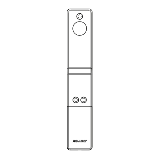
Diagram 1: Product Components
A
D
H
B
E
G
I
C
F
J
K
1 of 8
Advertisement
Table of Contents

Subscribe to Our Youtube Channel
Related Manuals for Assa Abloy HES KS100 Aperio


Summary of Contents for Assa Abloy HES KS100 Aperio
- Page 1 KS100 Aperio ® ® Wireless Cabinet Lock Installation & Operating Instructions Product Contents Diagram 1: Product Components Lock Body Battery Bracket Handle Assembly SFIC Cam & Spacer Handing Selectors (L) or (R) 3x Wire Connector Screw A: #1/4-20 x 1/2" Truss Head Phillips Screw B: #8/32 x 5/16"...
-
Page 2: Product Specifications
Product Specifications • Wireless Frequency • HID multiCLASS SE technology ® ® Credentials Supported: 2.4GHz, IEEE 802.15.4, using AES 128-bit encryption • High Frequency (13.56 MHz): • Lock Battery Type AA Lithium, 1.5 Volts (V) » HID iCLASS ® • Battery Life 50,000 cycles* »... -
Page 3: Installing The Lock
Installing the Lock Diagram 3: Install Tamper 1. Locate the 150mm x 25mm Switch lock cutout on the door. Connect battery cable and optional DPS cable to lock body. Secure battery bracket to lockbody using 3x screw B. 2. Ensure lock body is flush against the mounting surface to depress tamper switch. -
Page 4: Installing Batteries
Installing Batteries Loosen screw on battery cover, slide cover down, and install batteries in the appropriate orientation. Diagram 6: Batteries Diagram 7: Micro USB Micro USB Port For emergency power & local (hard wired) firmware updates, use micro USB port located on the side of the KS100 reader. -
Page 5: Optional Accessories
KS-CAM45 CAM: 45MM - 1 (18mm Depth) AH20W14 ASSA ABLOY Aperio™ AH20 1:1 Wiegand Hub EXT-10-ANT ASSA ABLOY Aperio™ Hub External Antenna - 3,9 dBi Omnidirectional APA-10-PC ASSA ABLOY Aperio™ Programming Kit APD-10-USB ASSA ABLOY Aperio™ USB Radio Dongle 5 of 8... -
Page 6: Led Codes
Aperio Hub Specifications • Approvals CE, ETL, FCC, IC, C-Tick • Radio Standard IEEE 802.15.4(2.4GHz) – 15 channels (11-25) • Safety & Emissions • Encryption (RadioCommunications) FCC 47CFR Part 15 subpart B and subpart C; IC RSS-210 EN ETSI 301 489-17 v2.1.1; ENETSI AES 128 bits 300 328 v1.7.1;... -
Page 7: Connecting The Hub
Connecting the Hub The following applies only to Aperio factory paired kits with AH20 Hubs. 1. Connect the Wiegand D1, D0, red, and green LED signals. NOTE: The Green LED input is used to grant access to the cabinet lock. If the Green LED signal is not available to indicate approved access, the approval input can be activated by a relay with “NO”... - Page 8 WARNING Conformité aux normes FCC Cet équipement a été testé et trouvé conforme aux limites pour un dispositif numérique de classe B, conformément à la Partie 15 des règlements de la FCC. FCC Statement Ces limites sont conçues pour fournir une protection This equipment has been tested and found to comply raisonnable contre les interférences nuisibles dans une with the limits for a class B digital device, pursuant to part...
Need help?
Do you have a question about the HES KS100 Aperio and is the answer not in the manual?
Questions and answers