Table of Contents
Advertisement
Quick Links
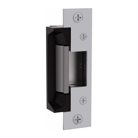
Product Components
5200 Electric Strike Body
1
Electrical Specifications
Electrical Ratings for Solenoid
Continuous Duty
Resistance in Ohms
Amps
Solenoids are rated at +/- 10% indicated value.
*10% maximum duty cycle (2 minutes maximum on time)
Indoor use only
Minimum Wire Gauge Requirements
(Based on Round Trip)
200 feet or less
200 – 300 feet
300 – 400 feet
ASSA ABLOY, the global leader
in door opening solutions
5200 Series Electric Strike
Installation Instructions
Trim Enhancer
2
1
Diagram 1: Product Components
24 VDC
Intermittent Duty*
12 VDC
Resistance in Ohms
50
200
Amps
.12
.24
Solenoid Voltage
12 VDC
24 VDC
18 gauge
20 gauge
16 gauge
18 gauge
14 gauge
16 gauge
12-Volt and 24-Volt Pigtails
3
2
3
24 VAC
12–16 VAC
50
200
.12
.24 – .32
HES, Inc.
Phoenix, AZ
800-626-7590
www.hesinnovations.com
1
Advertisement
Table of Contents

Related Manuals for Assa Abloy Hes 5200 Series


Summary of Contents for Assa Abloy Hes 5200 Series
- Page 1 (Based on Round Trip) 12 VDC 24 VDC 200 feet or less 18 gauge 20 gauge 200 – 300 feet 16 gauge 18 gauge 300 – 400 feet 14 gauge 16 gauge ASSA ABLOY, the global leader in door opening solutions...
- Page 2 Installation CAUTION! Before connecting any device at the installation site, verify input voltage using a multimeter. Many power supplies and low voltage transformers operate at higher levels than listed. Any input voltage exceeding 10% of the solenoid rating may cause severe damage to the unit and will void the warranty. Preparing the Strike Preparing the Frame Note: For 12 VDC, the Plug In Connector (pigtail)
- Page 3 Installation (continued) LBM Wiring LBSM Wiring Brown Common White Common Orange Blue Normally Open Normally Open Normally Closed Green Normally Closed Yellow White Brown Blue Orange Yellow Yellow Green Diagram 3: Latchbolt Monitor Diagram 4: Latchbolt Strike Monitor LOCKSETS Converting the Operation Mode Note 1: The 5200 series Electric Strikes are pre-set for FAIL SECURE OPERATION.
- Page 4 13/16" [20.6] 3/32" [2.3] Inches [mm] 504 Faceplate Option (10” x 1-3/8”), Radius Corners and Flat Faceplate Used with cylindrical locksets; four-point mounting for wood installations 3059006.002 rev C © 2015, Hanchett Entry Systems, Inc., an ASSA ABLOY Group company.
Need help?
Do you have a question about the Hes 5200 Series and is the answer not in the manual?
Questions and answers