Advertisement
Quick Links
HES 9400/9500/9600/9700
Electric Strike
Installation Instructions and Frame Preparation
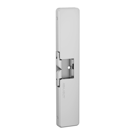
Product Components
A
9400/9500/9600/9700 Strike Body
B
9400/9500/9600/9700 Cover
C
1/4"-20 x 1" Mounting Screws
D
#10-32 & 10-24 Lockdown Screws (optional)
E
#6-32 x 1/4" Cover Screws
F
5/64" Hex Key
G
12-Volt and 24-Volt Pigtails
Electrical Specifications
Electrical Ratings for Solenoid
Continuous Duty
Resistance in Ohms
mA Continuous Duty
Solenoids are rated at +/- 10% indicated value.
Minimum Wire Gauge
Requirements
(Based on Round Trip)
200 feet or less
200 – 300 feet
300 – 400 feet
UL1034
• Static Strength: 1500 lbs
• Dynamic Strength: 70 ft – lbs
• Endurance: 250,000 cycles
UL294 Performance Levels
• Destructive Attack: Level I
• Line Security: Level I
• Endurance: Level IV
• Standby Power: Level I
NOTE: Installation wiring for the product and
wiring methods shall be in accordance with the
National Electrical Code, ANSI/NFPA70
12 VDC
24 VDC
24
96
500
250
Solenoid Voltage
12 VDC
24 VDC
18 gauge
22 gauge
16 gauge
22 gauge
16 gauge
20 gauge
Diagram 1: Product Components
A
C
F
D
E
B
G
1
Advertisement

Related Manuals for Assa Abloy HES 9400


Summary of Contents for Assa Abloy HES 9400
- Page 1 HES 9400/9500/9600/9700 Electric Strike Installation Instructions and Frame Preparation Product Components Diagram 1: Product Components 9400/9500/9600/9700 Strike Body 9400/9500/9600/9700 Cover 1/4"-20 x 1" Mounting Screws #10-32 & 10-24 Lockdown Screws (optional) #6-32 x 1/4" Cover Screws 5/64" Hex Key 12-Volt and 24-Volt Pigtails...
- Page 2 THEN REFER to Diagrams 5 and 6 to (- NEG) Red/green complete wiring (see page 3). Verifying the Operation Mode The HES 9400/9500/9600/9700 Electric Strike is pre-set for FAIL SECURE OPERATION as shown in Diagram 3. Diagram 3: Fail Secure Operation VERIFY that both keepers are in FAIL SECURE OPERATION.
- Page 3 Preparing the Frame NOTE: When using a Corbin Russwin Series 5000 or Yale 7000 Series equipped with an Diagram 5 offset deadlatch, the deadlatch is located Latchbolt Monitor just above the vertical alignment line as White White shown in the dimesions on page 4. Common Orange Orange...
- Page 4 [22.5mm] Aluminum Frame with Blade Stop Patent Pending and/or patent www.assaabloydss.com/patents Copyright © 2019, Hanchett Entry Systems, Inc., an ASSA ABLOY Group company. All rights reserved. Reproduction in whole or in part without the techsupport.esh@assaabloy.com | assaabloyesh.com express written permission of Hanchett Entry Systems, Inc. is prohibited.
Need help?
Do you have a question about the HES 9400 and is the answer not in the manual?
Questions and answers