Table of Contents
Advertisement
Available languages
Available languages
Advertisement
Chapters
Table of Contents

Subscribe to Our Youtube Channel
Summary of Contents for Gerber Technology GERBERplotter XLp Series
-
Page 4: Copyright Notice
Copyright Notice Copyright © 2010 by Gerber Technology, a Business Unit of Gerber Scientific International, Inc. All rights reserved. This document may not be reproduced by any means, in whole or in part, without the written permission of the copyright owner. This document is part of the proprietary articles furnished to document the GERBERplotter™... -
Page 5: Table Of Contents
Customer Support ................1 Safety Instructions................3 Hardware Installation ..............7 Software Overview ..............21 WinPlot Installation..............21 XLp Interface Software Installation ..........22 Calibration Procedures...............38 Complete a Test Plot on the GERBERplotter XLp Series ..42 Appendix ..................46 Troubleshooting .................46 Machine Specifications ..............47 Glossary ..................48 ________________________________________________... - Page 6 Table of Figures Figure 1. WEEE label................2 Figure 2. GERBERplotter XLp Series ............ 5 Figure 3. Control Panel ................6 Figure 4. Crate contents................. 7 Figure 5. Component Box ..............8 Figure 6. Right Side Column removed and balanced......9 Figure 7.
-
Page 8: Customer Support
Introduction The GERBERplotter XLp Series plotters are ideal for plotting in an ultra wide format yet are small enough to fit into any design or pattern making area. These compact upright plotters are quiet, easy to install, use minimal floor space and can be conveniently set against a wall. -
Page 9: Figure 1. Weee Label
Advanced Technology Centers Gerber's Advanced Technology Centers are dynamic hubs for product demonstrations, software testing, system training, engineering and R&D activities. North America Phone: 1.800.826.3243 (toll free in USA) 1.860.871.8082 (outside USA) 1.866.796.8570 Spanish China Phone: +86 (21) 5445.0505 Europe Phone: +32 (2) 716.0311 Vietnam... -
Page 10: Safety Instructions
Safety Instructions Read and understand all Safety Instructions before operating the GERBERplotter to prevent personal injury, death, or equipment damage. Safety Labels The Safety Labels in Table 1 are located at various parts of the GERBERplotter. Symbol Description Electrical ground to frame Sharp Edge Do Not Touch... -
Page 11: Replacing Parts
Failure to comply could result in personal injury. Ink Cartridges Refilling cartridges or using incompatible inks could result in equipment damage. Use only approved ink cartridges from Gerber Technology. Ink Hazards If removed from the ink cartridge, the ink may cause the following: •... -
Page 12: Figure 2. Gerberplotter Xlp Series
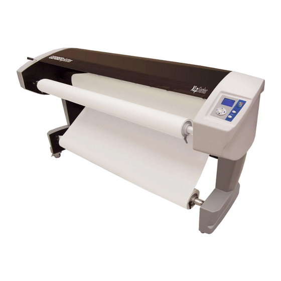
System Description Hardware Overview Figure 2. GERBERplotter XLp Series Key to Figure & Description (1) Nip Bar Lever (4) Feed Roll Bar This lever controls the Nip Bar and The Feed Roll Bar holds the Paper Pinch Rollers and is located above Roll and supplies paper to the the Left Side Column. -
Page 13: Figure 3. Control Panel
Figure 3. Control Panel Key to Figure & Control Panel description (1) Arrow Keys (3) Menu button Used to navigate commands on Used to view menus on the LCD the LCD screen in four directions: screen. left, right, up and down. (2) LCD Screen (4) Enter button Displays and controls the plotter... -
Page 14: Hardware Installation
Hardware Installation NOTE: Two people are required to complete the Hardware Installation. Lift and remove the top of the crate to view the XLp plotter (Figure 4) and contents (Figure 5). Figure 4. XLp Plotter in crate Figure 5. Crate contents Key to Figure Component Box Left Side Column... -
Page 15: Figure 5. Component Box
Remove the cardboard Component Box and review contents (Figure 6). Figure 6. Component Box Key to Figure Adhesive tape Mandrels USB Cable Fuses Hex Wrenches Screws HP Inkjet Cartridge(s) ________________________________________________... -
Page 16: Figure 6. Right Side Column Removed And Balanced
Remove the Left and Right Side Columns from crate and balance them (Figure 7). Figure 7. Right Side Column removed and balanced Hold Crossbeam up to Right Side Column (Figure 8) and align with the Screws. Use the Hex Wrenches and Screws to attach the crossbeam to the Right Side Column. -
Page 17: Figure 8. Two Screws Attaching Head Unit And Crossbeam
Place the Head Unit on top of the two side columns. Screw in the left and right screws to attach (Figure 9). Repeat on the opposite side. Figure 9. Two screws attaching Head Unit and Crossbeam Key to Figure 1. Screws On the interior of the Right Side Column, remove the Feed Motor Cable from the plastic holder and plug port located inside the Right Side Column (Figure 10). -
Page 18: Figure 10. Usb Cable
Plug the “B” end of the USB cable into the port underneath the Right Side Column (Figure 11). 10. Plug the opposite end of the USB cable into the computer. NOTE: If a network cable is used, plug it into the port next to the USB cable and into the corresponding network port. -
Page 19: Figure 11. Rubber Stop On Left Side
11. During shipping, the Front Cover can shift and sometimes lose its alignment. If it is not lying flat, twist the Rubber Stops located underneath the left and right of the Front Cover until it rests evenly on both sides (Figure 12). 12. - Page 20 13. Use the Voltage Switch to select 110V or 220V. Figure 13. Voltage switch ________________________________________________...
- Page 21 13. Locate the Power Cord pocket on the side of the crate (Figure 14). Remove the panel and retrieve the Power Cord stored inside. Figure 14. Power Cord pocket ________________________________________________...
-
Page 22: Figure 12. Power Cord
14. Plug the Power Cord into the Power Cord Socket (Figure 15). 15. Plug the opposite end into a wall electrical socket. 16. Push the Power Switch to the I (ON) position to turn the plotter power on. NOTE: The plotter will beep when powered on. Figure 15. -
Page 23: Figure 13. Paper Roll And Components
17. Insert the Feed Roll Bar through the hollow core in the Paper Roll (Figure 16). Figure 16. Paper roll and components Key to Figure Paper Roll Feed Roll Bar Mandrels 18. Place Mandrels on each end of the Feed Roll Bar and use the attached black levers to tighten next to the Paper Roll (Figure 17). -
Page 24: Figure 15. Paper Fed Through The Nip Bar And Pinch Rollers
19. Place the Feed Roll Bar onto the Left and Right Columns to properly install the Paper Roll. 20. Follow the direction of the yellow arrows and place the Nip Bar Lever in the UP position. This disengages the drive to move the paper and allows a new roll to be installed. -
Page 25: Figure 16. Feeding Paper Toward Front Of Plotter
24. Pull paper through to front of plotter through the Pinch Rollers and Nip Bar. Figure 19. Feeding paper toward front of plotter 25. Place paper under the Front Dancer Bar and pull forward. a. To let paper fall to the floor: Place the paper over the Front Dancer Bar. -
Page 26: Figure 18. Plotter With Paper Installed
26. Follow the direction of the yellow arrows and place the Nip Bar Lever in the DOWN position. Figure 21. Plotter with paper installed 27. Remove one of the HP45 Inkjet Cartridge packages from the Component Box (Figure 6). Remove and discard the green film attached to the bottom of the cartridge. -
Page 27: Figure 19. Installed Inkjet Cartridges (Xlp95)
Figure 22. Installed Inkjet Cartridges (XLp95) ________________________________________________... -
Page 28: Software Overview
Software Overview The XLp Series plotters use WinPlot/AccuMark and the XLp Interface software to run the plotter. The two separate software CDs are shipped with each plotter. NOTE: The XLp Series plotters are compatible with AccuMark 8.2.2 and up. If a customer has an older version (prior to version 8.2.2) of AccuMark and uses an XLp plotter, they will need to upgrade AccuMark or supply a separate networked Windows PC to run WinPlot with the XLp plotter update. -
Page 29: Xlp Interface Software Installation
Under GT Programs, click Install WinPlot Software. Follow the InstallShield prompts to install WinPlot. Return to the WinPlot Installation screen after WinPlot is installed. Under GT Programs, click XLp Update for Version 8.2.2 – 8.4.0 (Install WinPlot/AccuMark first). Follow the InstallShield prompts to install the XLp Update. XLp Interface Software Installation Insert the XLp Interface software CD into the CD drive. -
Page 30: Figure 22. Gerber Device Configuration
Gerber Device Configuration On the Start menu, point to Control Panel. Double click the Gerber Device icon. The Gerber Device Configuration window will appear (Figure 25). Click the Plotter tab. In the Type box, select XLP USB PLOTTER (XLP-PLOTTER). Click Apply. Click OK. - Page 31 Software Overview The installed software version number will be displayed on the Title Bar of each screen. TCP/IP Configuration NOTE: The plotter must be powered on and plugged in to the computer before beginning the TCP/IP connection. Right click the XLp Interface icon located on the Status Area of the Task Bar.
- Page 32 Select IP Communication. Figure 27. System Setting initial screen ________________________________________________...
- Page 33 In the Network Adapter List, select the desired network connection for the plotter. Click the Lan Scan button. Figure 28. System Setting window, IP Communication ________________________________________________...
- Page 34 The MAC Address List box will propagate after the Lan Scan is complete. Select the desired Mac Address in the Mac Address List box. Type the IP Address, Subnet Mask and Gateway specific to the network being configured. Figure 29. System Setting window, IP Communication ________________________________________________...
- Page 35 Click the Connect button. 10. The Setting Succeed! window will appear. Click OK to confirm the configurations. Figure 30. System Setting window, Setting Succeed box ________________________________________________...
- Page 36 11. Click Set IP Address. 12. The Please Restart Program and Plotter! window will appear. Click OK to confirm. Figure 31. Plotter and program restart window 13. Click the Close button to close the XLp Interface. The plotter will beep and the LCD Screen will prompt a restart. 14.
- Page 37 16. The window in Figure 32 will appear with tabs for further configuration. Figure 32. System Setting window after configuration ________________________________________________...
-
Page 38: Figure 23. Xlp Interface Icon
System Setting Click the XLp Interface Icon located on the Status Area of the Task Bar. Select XLp Interface. Select System Setting. Figure 33. XLp Interface Icon The System Setting window will appear. ________________________________________________... -
Page 39: Figure 24. Machine Setting Window, Plot Tab
System Setting Window, Plot tab The Plot tab allows configuration of the Line Width, Y Plot Origin, and ink usage settings. Figure 34. System Setting window, Plot tab ________________________________________________... -
Page 40: Figure 25. Machine Setting Window, Ink Tab
System Setting Window, Ink tab The Ink tab allows configuration of the Ink Counter Reset Values. Figure 35. System Setting window, Ink tab ________________________________________________... -
Page 41: Figure 26. Machine Setting Window, Paper Tab
System Setting Window, Paper tab The Paper tab allows configuration of the Paper Roll length and corresponding paper preferences. Figure 36. System Setting window, Paper tab ________________________________________________... -
Page 42: Figure 27. Machine Setting Window, System Tab
System Setting Window, System tab The System tab allows selection of the units of measure and settings such as the Top Cover Alarm, to run a Cartridge Auto test, and to Clean the Cartridge After Each Plot. Figure 37. System Setting window, System tab ________________________________________________... -
Page 43: Figure 28. Machine Setting Window, Communication Tab
System Setting Window, Communication tab The Communication tab allows selection of USB or IP Communication. Figure 38. System Setting window, Communication tab ________________________________________________... -
Page 44: Figure 29. Machine Setting Window, Calibration Tab
System Setting Window, Calibration tab The Calibration settings allow configuration of the following calibrations: Cartridge Alignment, Cartridge Overlap, Y Head Calibration, Y Gap Calibration, and X Length and Y Length (Box Test). Figure 39. System Setting window, Calibration tab (XLp95 settings) ________________________________________________... -
Page 45: Calibration Procedures
Calibration Procedures The Calibration procedures below should be performed when the plotter is initially installed and when ink cartridges are changed. X Gap Calibration Click the X Gap button (Figure 39) to run the X Gap calibration. NOTE: The plotter will begin printing. Check the plot for the line and corresponding numeric value that represents the best match of the two printed lines (Figure 40). -
Page 46: Figure 32. Cartridge Overlap Calibration
Cartridge Overlap Calibration Click the Start Cartridge Overlap Alignment button (Figure 39) to run the Cartridge Overlap Calibration. NOTE: The plotter will begin printing. Check the plot for the line and corresponding numeric value that represents the best match of the two printed lines. Enter the numeric value from step 2 in the Cartridge box. -
Page 47: Figure 34. Y Gap Calibration
Forward/Reverse Alignment Calibration Click the Start F/R Alignment button (Figure 39) to run the Forward/Reverse Alignment Calibration. NOTE: The plotter will begin printing. Check the plot for the line and corresponding numeric value that represents the best match of the two printed lines. Add or subtract the value from step 2 from 7. - Page 48 X Length and Y Length (Box Test) The Box Test is used to determine the plotter’s printing tolerance (+/- 1mm) by printing a series of 1 x 1 meter boxes. This test should be performed when the plotter is initially installed and when ink cartridges are changed.
-
Page 49: Complete A Test Plot On The Gerberplotter Xlp Series
Complete a Test Plot on the GERBERplotter XLp Series This section provides step-by-step instructions to complete a plot using the XLp Series and WinPlot. To complete a plot using AccuMark, refer to the AccuMark plotting documentation. Read the Safety Instructions section before operating the plotter. Ensure the XLp Series plotter is turned on and online. -
Page 50: Figure 36. Winplot Screen
The WinPlot window will appear (Figure 45). Click Add. Figure 45. WinPlot screen ________________________________________________... -
Page 51: Figure 37. Choose Files To Plot Window
The Choose files to plot window will appear (Figure 46). Browse to one of the following locations: c:/ Program Files/Gerber Technology/AccuMark V8/WinPlot/Samples c:/ WinPlot/Samples. Select 1MeterMarker.PLT and click Add file(s) (Figure 46). Figure 46. Choose files to plot window ________________________________________________... -
Page 52: Figure 38. Winplot Box
In the WinPlot box, click Plot to begin plotting. Figure 47. WinPlot box The plotter will begin printing. Congratulations! A plot using the GERBERplotter XLp Series has been completed. The plotter is now ready to plot using any .plt file. ________________________________________________... -
Page 53: Appendix
Appendix Supplies To order Supplies, call 1.800.321.2448 or visit https://www.gerberscientific.net/GT/eCommerce/login.aspx to place an online order. Commonly used supplies and corresponding part numbers are listed below. Item Part Number HP 45 Inkjet Cartridge 558500006 Mandrel 94714000 Paper take-up bar 94541000 Table 2. Supplies and part numbers Troubleshooting Error message Possible cause... -
Page 54: Machine Specifications
Machine Specifications XLp50 XLp95 AC Power 110VAC or 220VAC 50-60HZ Max Power Consumption 250W Speed 50 m 95 m Resolution 300dpi Length Accuracy Less than .1% Cartridge Availability HP51645A ink cartridge Cartridge Count Paper Roll Inner Diameter 7.6cm (2.9 in. ) Paper Roll Outer Diameter 30cm (18.8 in. -
Page 55: Glossary
Glossary Casters Two casters are attached to the bottom of the Right and Left Side Columns to assist in moving the plotter. Control Panel The Control Panel controls plotter functions. Crossbar A large metal bar that holds the Right and Left Side Columns together to support the Head unit. - Page 56 Mandrel Fasteners used to secure paper rolls to the Feed Roll Bar. Nip Bar Lever This lever controls the Nip Bar and is located above the Left Side Column. The DOWN position is the normal operating position and firmly holds the paper in place. The UP position loosely grips the paper and is used when loading paper.
- Page 59 Aviso sobre derechos de autor Copyright © 2010 por Gerber Technology, una unidad comercial de Gerber Scientific International, Inc. Reservados todos los derechos. Se prohíbe la copia de este documento, en su totalidad o en parte, sin la autorización por escrito del propietario de los derechos de autor. Este documento forma parte de los artículos registrados que se suministran...
- Page 60 Índice Asistencia técnica ................1 Instrucciones de seguridad ............3 Instalación del hardware ..............7 Descripción del software ............21 Instalación de WinPlot..............22 Instalación del software de la interfaz del XLp ......23 Procedimientos de calibración ...........39 Haga un gráfico de prueba en el GERBERplotter serie XLp ..44 ...
- Page 61 Tabla de figuras Figura 1. Etiqueta WEEE ............... 2 Figura 2. GERBERplotter serie XLp............5 Figura 3. Panel de control ..............6 Figura 4. Graficador XLp en la caja............7 Figura 5. Contenidos de la caja.............. 7 ...
- Page 62 Figura 43. Calibración de la alineación de avance/inversión ....42 Figura 44. Icono de la interfaz del XLp..........44 Figura 45. Pantalla de WinPlot............. 45 Figura 46. Ventana "Choose files to plot" ("Elegir archivos a graficar") 46 ...
-
Page 63: Asistencia Técnica
Introducción Los graficadores GERBERplotter de la serie XLp son ideales para hacer gráficos en formato ultra ancho, al tiempo que su tamaño es lo suficientemente pequeño como para caber en cualquier espacio designado para la elaboración de diseños o patrones. Estos compactos graficadores verticales son silenciosos, fáciles de instalar, ocupan un espacio mínimo y pueden instalarse cómodamente contra una pared. - Page 64 Centros de tecnología de avanzada Los centros de tecnología avanzada de Gerber son instalaciones dinámicas donde se realizan demostraciones de productos, pruebas de software, capacitación en sistemas, actividades técnicas y labores de investigación y desarrollo. América del Norte Teléfono: 1.800.826.3243 (llamada gratuita en los EE. UU.) 1.860.871.8082 (fuera de los EE.
-
Page 65: Instrucciones De Seguridad
Instrucciones de seguridad Para evitar lesiones corporales, muerte o daños al equipo, es necesario leer y entender todas las instrucciones de seguridad antes de utilizar el GERBERplotter. Etiquetas de seguridad Las etiquetas de seguridad mostradas en la Tabla 1 se encuentran en diversas partes del GERBERplotter. -
Page 66: Cartuchos De Tinta
Notifique a un representante del Servicio local de atención al cliente de Gerber acerca de toda pieza rota o faltante. No utilice piezas ni haga modificaciones que no estén aprobadas por Gerber Technology. De lo contrario, podría sufrir lesiones o provocar daños al equipo. - Page 67 Descripción del sistema Descripción general del hardware Figura 2. GERBERplotter serie XLp Claves de la figura y descripción (1) Palanca de la barra de presión (4) Barra del rodillo de Esta palanca, que está situada en la alimentación columna lateral izquierda, controla la La barra del rodillo de barra de presión y los rodillos de alimentación sostiene el rollo de...
- Page 68 Figura 3. Panel de control Claves de la figura y descripción del panel de control (1) Teclas de flechas (3) Botón de menú Se usan para navegar los mandos Se utiliza para ver menús en la de la pantalla LCD en cuatro pantalla LCD.
-
Page 69: Instalación Del Hardware
Instalación del hardware NOTA: Se necesita la colaboración de dos personas para realizar la instalación del hardware. Levante y quite la parte superior de la caja para ver el graficador XLp (Figura 4) y su contenido (Figura 5). Figura 4. Graficador XLp en la caja Figura 5. - Page 70 Saque la caja de componentes de cartón y examine el contenido (Figura 6). Figura 6. Caja de componentes Claves de la figura Cinta adhesiva Mandriles Cable USB Fusibles Llaves Tornillos hexagonales Cartucho(s) de chorro de tinta HP ________________________________________________...
- Page 71 Saque las columnas laterales izquierda y derecha de la caja y equilíbrelas (Figura 7). Figura 7. Columna lateral derecha fuera de la caja y equilibrada Sostenga el travesaño contra la columna lateral derecha (Figura 8) y alinéelo con los tornillos. Con los tornillos suministrados, sujete el travesaño a la columna lateral derecha.
- Page 72 Figura 8. Sujeción del travesaño a la columna lateral derecha Coloque la unidad superior encima de las dos columnas laterales. Atornille los tornillos de la izquierda y de la derecha (Figura 9). Repita este procedimiento en el lado opuesto. Figura 9. Sujeción de la unidad superior al travesaño mediante dos tornillos Claves de la figura 1.
- Page 73 En el interior de la columna lateral derecha, saque el cable del motor de alimentación del sujetador plástico y puerto de enchufe situados dentro de la columna lateral derecha (Figura 10). Figura 10. Cable del motor de alimentación (dentro de la columna lateral derecha) Enchufe el extremo “B”...
- Page 74 Figura 11. Cable USB 11. Es posible que la cubierta delantera se mueva durante el envío y pierda su alineación. Si no está colocada en posición horizontal, gire los topes de goma situados debajo de la izquierda y la derecha de la cubierta delantera hasta que quede apoyada uniformemente en ambos lados (Figura 12).
- Page 75 Figura 12. Tope de goma izquierdo y tornillo Claves de la figura Tope de goma Tornillo 13. Con el conmutador de tensión, seleccione 110 V o 220 V. Figura 13. Conmutador de tensión ________________________________________________...
- Page 76 13. Ubique la toma del cable de alimentación en el lado de la caja (Figura 14). Retire el panel y saque el cable de alimentación que está adentro. Figura 14. Toma del cable de alimentación 14. Enchufe el cable de alimentación en la toma del cable de alimentación (Figura 15).
- Page 77 Figura 15. Cable de alimentación Claves de la figura Interruptor de encendido en la posición de encendido Cable de alimentación en la toma 17. Inserte la barra del rodillo de alimentación a través del núcleo hueco del rodillo de papel (Figura 16). Figura 16.
- Page 78 Figura 17. Rodillo de papel y componentes Claves de la figura Rodillo de papel Barra del rodillo de alimentación Mandriles 19. Coloque la barra del rodillo de alimentación en las columnas izquierda y derecha para instalar adecuadamente el rodillo de papel. 20.
- Page 79 Figura 18. Papel alimentado a través de la barra de presión y los rodillos de arrastre 24. Tire del papel hacia el frente del graficador y a través de los rodillos de arrastre y de la barra de presión. Figura 19. Alimentación del papel hacia el frente del graficador ________________________________________________...
- Page 80 25. Coloque el papel debajo de la barra móvil frontal y hálelo hacia adelante. a. Para dejar que el papel caiga en el piso: Deje el papel debajo de la barra móvil frontal. b. Para enrollar el papel en el rodillo: Con la cinta adhesiva suministrada, pegue el extremo del papel a la barra tensora del papel.
- Page 81 Figura 21. Graficador con papel instalado 27. Saque uno de los paquetes de cartuchos de chorro de tinta HP45 de la caja de componentes (Figura 6). Retire y deseche la película verde que está en la parte inferior del cartucho. 28.
- Page 82 Figura 22. Cartuchos de chorro de tinta instalados (XLp95) ________________________________________________...
-
Page 83: Descripción Del Software
Descripción del software Los graficadores de la serie XLp funcionan con WinPlot/AccuMark y con el software de interfaz XLp. Los dos CD individuales se envían con cada graficador. NOTA: Los graficadores de la serie XLp son compatibles con AccuMark 8.2.2 y versiones más modernas. Si un cliente tiene una versión más antigua de AccuMark (anterior a la 8.2.2) y utiliza un graficador XLp, tendrá... -
Page 84: Instalación De Winplot
Instalación de WinPlot Inserte el CD del software WinPlot en la unidad de CD. Aparecerá la pantalla de instalación de WinPlot (Figura 23). Figura 23. Pantalla de instalación de WinPlot Abajo de GT Programs ("Programas de GT"), haga clic en Install WinPlot Software ("Instalar software WinPlot"). -
Page 85: Instalación Del Software De La Interfaz Del Xlp
Instalación del software de la interfaz del XLp Inserte el CD del software de la interfaz del XLp en la unidad de CD. Aparecerá la ventana de instalación de la interfaz del XLp (Figura 24). Figura 24. Ventana de instalación de la interfaz del XLp Abajo de GT Programs, haga clic en Install XLp Series Software ("Instalar el software de la serie XLp"). - Page 86 Configuración del dispositivo Gerber En el menú Start ("Inicio"), apunte a Control Panel ("Panel de control"). Haga doble clic en el icono del dispositivo Gerber. Aparecerá la ventana Gerber Device Configuration ("Configuración del dispositivo Gerber") (Figura 25). Haga clic en la pestaña Plotter ("Graficador"). En el cuadro Type ("Tipo"), seleccione XLP USB PLOTTER (XLP-PLOTTER) ("XLP-GRAFICADOR").
- Page 87 Descripción del software El número de la versión de software instalada aparecerá en la barra de título de cada pantalla. Configuración TCP/IP NOTA: El graficador debe estar encendido y enchufado a la computadora antes de comenzar la conexión TCP/IP. Haga clic con el botón derecho del ratón en el icono de Interfaz del XLp situado en el área de estatus de la barra de tareas.
- Page 88 Figura 27. Pantalla inicial "System Setting" En Network Adapter List ("Lista de adaptador de red"), seleccione la conexión de red deseada para el graficador. Haga clic en el botón Lan Scan ("Escán de Lan"). ________________________________________________...
- Page 89 Figura 28. Ventana "System Setting", comunicación IP Una vez se haga el Lan Scan, se propagará el cuadro de Lista de direcciones de MAC. En el cuadro Mac Address List ("Lista de direcciones de Mac"), seleccione la dirección Mac deseada. Introduzca IP Address ("Dirección de IP), Subnet Mask ("Máscara de subrred") y Gateway ("Puerta de enlace") específicos para la red que se está...
- Page 90 Figura 29. Ventana "System Setting", comunicación IP Haga clic en el botón Connect ("Conectar"). 10. Aparecerá la ventana "Setting Succeed!" ("Se establecieron los ajustes satisfactoriamente"). Haga clic en OK para confirmar las configuraciones. ________________________________________________...
- Page 91 Figura 30. Ventana "System Setting", cuadro "Setting Succeed" 11. Haga clic en Set IP Address ("Fijar dirección de IP"). 12. Aparecerá la ventana "Please Restart Program and Plotter!" ("Favor reiniciar el programa y el graficador"). Haga clic en OK para confirmar.
- Page 92 Figura 31. Ventana de graficador y reinicio del programa 13. Haga clic en el botón "Close" ("Cerrar") para cerrar la XLp Interface. El graficador emitirá un pitido y la pantalla LCD indicará el reinicio. 14. Apague el graficador XLp, y luego vuelva a encenderlo. 15.
- Page 93 Figura 32. Ventana "System Setting" después de la configuración ________________________________________________...
- Page 94 Ajustes del sistema Haga clic en el icono de Interfaz del XLp situado en el área de estatus de la barra de tareas. Seleccione XLp Interface. Seleccione System Setting. Figura 33. Icono de la interfaz del XLp Aparecerá la ventana "System Setting". ________________________________________________...
- Page 95 Ventana "System Setting", pestaña "Plot" La pestaña "Plot" ("Gráfico") permite configurar los parámetros "Line Width" (ancho de línea), "Y Plot Origin" (origen del gráfico Y) y de uso de la tinta. Figura 34. Ventana "System Setting", ficha "Plot" ________________________________________________...
- Page 96 Ventana "System Setting", pestaña "Ink" La pestaña "Ink" ("Tinta") permite configurar los valores de reajuste del contador de tinta. Figura 35. Ventana "System Setting", pestaña "Ink" ________________________________________________...
- Page 97 Ventana "System Setting", pestaña "Paper" La pestaña "Paper" ("Papel") permite configurar la longitud del rodillo de papel y las preferencias de papel correspondientes. Figura 36. Ventana "System Setting", pestaña "Paper" ________________________________________________...
- Page 98 Ventana "System Setting", pestaña "System" La pestaña System ("Sistema") permite seleccionar las unidades de medición y parámetros como "Top Cover Alarm" ("Alarma de cubierta superior"), ejecutar "Cartridge Auto test" ("Prueba automática del cartucho") y "Clean the Cartridge After Each Plot" ("Limpiar el cartucho después de cada gráfico").
- Page 99 Ventana "System Setting", pestaña "Communication" La pestaña Communication ("Comunicación") permite seleccionar el tipo de comunicación (USB o IP). Figura 38. Ventana "System Setting", pestaña "Communication" ________________________________________________...
- Page 100 Ventana "System Setting", pestaña "Calibration" Los ajustes de la pestaña Calibration ("Calibración") permiten configurar las siguientes calibraciones: "Cartridge Alignment" ("Alineación del cartucho"), "Cartridge Overlap" ("Traslapo del cartucho"), "Y Head Calibration" ("Calibración del cabezal Y"), "Y Gap Calibration" ("Calibración de la separación Y") y "X Length" ("Longitud X") y "Y Length"...
-
Page 101: Procedimientos De Calibración
Procedimientos de calibración Los siguientes procedimientos de calibración deberán realizarse durante la instalación inicial del graficador y al cambiar los cartuchos de tinta. Calibración de la separación X Haga clic en el botón X Gap ("Separación X") (Figura 39) para ejecutar dicha calibración. - Page 102 Calibración del traslapo del cartucho Haga clic en el botón Start Cartridge Overlap Alignment ("Comenzar alineación del traslapo del cartucho") (Figura 39) para ejecutar la calibración correspondiente. NOTA: El graficador comenzará a imprimir. Examine el gráfico para observar la línea y determinar el correspondiente valor numérico que mejor represente las dos líneas impresas.
- Page 103 Calibración de la alineación de la separación del cartucho NOTA: El valor predeterminado es 261 (26,1 cm o 261 mm). Haga clic en el botón Start Cartridge Separation Alignment ("Comenzar alineación de la separación del cartucho") (Figura 39) para ejecutar la alineación del cabezal Y. NOTA: El graficador comenzará...
- Page 104 Calibración de la alineación de avance/inversión Haga clic en el botón Start F/R Alignment ("Comenzar alineación de avance/inversión") (Figura 39) para ejecutar la calibración correspondiente. NOTA: El graficador comenzará a imprimir. Examine el gráfico para observar la línea y determinar el correspondiente valor numérico que mejor represente las dos líneas impresas.
- Page 105 Mida y registre las mediciones en las direcciones X e Y. Introduzca estos valores en el cuadro Actual Length ("Longitud real"). Haga clic en Confirm ("Confirmar"). Haga clic en Apply. Actualice los nuevos valores del paso 3 en los cuadros XLength y YLength.
-
Page 106: Haga Un Gráfico De Prueba En El Gerberplotter Serie Xlp
Haga un gráfico de prueba en el GERBERplotter serie XLp Esta sección contiene las instrucciones detalladas para hacer un gráfico con la serie XLp y WinPlot. Para hacer un gráfico con el software AccuMark, consulte la documentación de graficado con AccuMark. Lea el apartado Instrucciones de seguridad antes de poner en funcionamiento el graficador. - Page 107 Figura 45. Pantalla de WinPlot Aparecerá la ventana Choose files to plot ("Elegir archivos a graficar") (Figura 46). Explore en una de las siguientes localidades: c:/ Program Files/Gerber Technology/AccuMark V8/WinPlot/Samples c:/ WinPlot/Samples. Seleccione 1MeterMarker.PLT y haga clic en Add file(s) ("Agregar archivo[s]") (Figura 46).
- Page 108 Figura 46. Ventana "Choose files to plot" ("Elegir archivos a graficar") En el cuadro WinPlot, haga clic en Plot para comenzar a graficar. Figura 47. Cuadro WinPlot El graficador comenzará a imprimir. ¡Felicitaciones! Se Imprimió un gráfico con el GERBERplotter serie XLp. El graficador está...
-
Page 109: Apéndice
Apéndice Suministros Para hacer pedidos de suministros, llame al 1.800.321.2448 o visite https://www.gerberscientific.net/GT/eCommerce/login.aspx para hacer un pedido en línea. A continuación se indican los suministros de uso común y sus correspondientes números de pieza. Artículo Número de pieza Cartucho de chorro de tinta HP 45 558500006 Mandril 94714000... -
Page 110: Especificaciones De La Máquina
Especificaciones de la máquina XLp50 XLp95 Alimentación de CA 110 V CA o 220 V CA 50-60 Hz Consumo máximo de 250 W potencia Velocidad 50 m 95 m Resolución: 300 dpi Precisión de longitud Menor de 0,1% Disponibilidad del Cartucho de tinta HP51645A cartucho Cantidad de cartuchos... - Page 111 Glosario Barra de presión y rodillos de arrastre Se trata de seis rodillos de arrastre acoplados a la barra de presión. Los rodillos de arrastre sostienen el papel en su lugar y lo alimentan a través del graficador. La tensión de la barra de presión se ajusta mediante la palanca de la barra de presión.
- Page 112 Interruptor de encendido/apagado Interruptor de encendido principal situado detrás de la columna lateral izquierda. Mandril Sujetadores que se utilizan para afianzar los rodillos de papel a la barra del rodillo de alimentación. Palanca de la barra de presión Esta palanca controla la barra de presión y está situada arriba de la columna lateral izquierda.
- Page 115 • 此文档及其内容在任何情况下都不得用于生产或者复制,不任命任何 权利或许可。 此文档信息若有更改,恕不另行通知。对于此文档中的错误或者装配和使 用过程中造成的意外或间接损失(例如利润,布料和生产时间的损失), 格柏科技有限公司、其子公司及附属机构将不承担任何责任。XLp™, WinPlot™和 GERBERplotter™是格柏科技的商标,版权所有。此手册中 所提及的其它公司名称,商标名称和产品名称是其各自公司的商标或者注 厂家:格柏科技,格柏科学有限 公司总部: 公司集团成员 Gerber Technology 地址:中国上海市漕河泾开发区 24 Industrial Park Road West 田州路 99 号 16 号楼 Tolland, CT 06084 USA Telephone 860.871.8082 1-2 层 邮编:200233 电话:+86 (21) 5445-0505 册商标。 94134002 10/10, 修订版 D...
- Page 116 目录 客户支持 ....................1 安全说明 ....................3 硬件安装 ....................7 软件纵览 ....................21 WINPLOT 软件安装 ................21 XLP 界面软件安装 ................22 设备校正程序..................38 在 XLP 系列绘图机上完成绘图测试 ............42 附录 ...................... 46 故障排除 ....................46 绘图机技术参数表................. 47 术语表....................48...
- Page 117 图表目录 图 1. WEEE 标志 .................... 2 图 2. 格柏 XLP 系列绘图机 ................5 图 3. 控制面板 ....................6 图 4. 木箱中的 XLp 绘图机................7 图 5. 箱内物品....................7 图 6.零件盒 ..................... 8 图 7. 取出后平稳放置的右侧支撑柱 ..............9 图 8. 将横梁和右侧支撑柱连接..............10 图...
- Page 118 图 41. 墨盒 X 间距校正 ................. 41 图 42. 1#2#墨盒 Y 轴间距校正..............42 图 43. Y 轴往返差校正 .................. 42 图 44. XLp 界面标志 ..................44 图 45. WinPlot 窗口 ..................45 图 46. 选择绘图文件 ..................46 图 47. WinPlot 窗口 ..................47 表格...
- Page 119 概要 XLp 系列绘图机是超宽幅面绘图的理想选择,它体积小,能够适合任何 设计或者纸样制作的场地要求。这种结构紧凑的直立式绘图机,运行安 静,易于安装,占地面积小,可以方便地靠墙放置。 XLp 系列喷墨绘图机易于使用,绘图幅面宽,可以进行可靠、高质量的 输出工作且运行成本小。它与格柏所有产品系统相兼容,提供基于 Windows 的图形界面,在主操作系统上能够直观控制并查看状态信息。 客户支持 如有任何疑问或技术问题,请与当地客户服务中心联系。 拨打电话之前,请在下列空格中填写具体信息,以备使用: 当地客户服务中心 电话号码: ____________________________ 销售订单号: ____________________________ 设备购买日期: ____________________________ 产品名称和类型: GERBERplotter XLp Series 现有备用设备: ___________________________ 软件(包括版本号码): ___________________________ 问题描述以及电脑或者显示屏上的错误信息. 客户服务中心 格柏全球客户服务中心由精通多种语言、训练有素的专业团队组成,随时 为您提供优质服务。如需查找当地客户服务中心,请访问下列网络连接: 。 www.gerbertechnology.com/default.asp?contentID=266.
-
Page 120: 图 1. Weee 标志
领先科技中心 格柏领先科技中心是产品售前演示、软件测试、设备培训、工程技术和产 品研发的活动中心。 北美 电话号码: 1-800-826-3243 (美国范围内免费) 1-860-871-8082 (美国之外地区) 1-866-796-8570 (西班牙) 中国 电话号码: +86 (21) 5445-0505 欧洲 电话号码: +32 (2) 716-0311 越南 电话号码: +84 (8) 984-7080 废弃电子设备环保法规(WEEE) 仅仅针对欧盟成员国! 根据针对 2005 年 8 月 13 日以后产品中废电机电子产品的法规要求,全部 格柏产品标注了 WEEE 标记。该法规要求电机电子产品在报废后进行收 。 集及处理。请参考当地法规的具体要求 图... - Page 121 安全说明 为了避免您在使用本产品时产生不必要的人员伤亡或财物损失,请在运行 XLp 系列之前,务必仔细阅读并理解以下安全说明。 安全标志 这些安全标志位于表 1 绘图机的不同部件上。 Symbol Description 电面结构 特别注意 请勿触摸光栅! 表格 1. 安全标志 警告和警示 此手册包含操作步骤之前的警告和警示。请严格遵守这些预防措施,以免 造成人员伤害或者设备损坏。 • 警告位于可能导致个人伤亡或者设备损坏的步骤之前。 • 警示位于可能导致设备损坏的步骤之前。 危险步骤 请遵守警告和警示。在安装过程中请遵守设备安全操作所必需的所有安全 说明。 切忌独自维修设备 请勿独自进行设备维修操作。设备维修时必须确保另一个人在场,必要时 可以执行急救工作。...
- Page 122 带电电路 确保电源(电压)线接地良好,连接正确。 经受培训的维修人员进入这些区域工作之前,必须切断电流以确保人身安 全。配备一个符合当地电气规范要求的总开关,用于切断各路电源。 切忌在易爆环境中操作 切忌在易爆环境中操作 使用易燃液体(譬如清洁剂)时,务必小心谨慎。请不要在易燃气体或烟 雾附近操作设备。 移动机器 手不要触碰移动绘图机部件以防造成人身伤害。绘图机运行过程中,请不 要靠近。 零件更换 如有零件故障或遗失,请通知格柏现场服务工程师。请不要使用未经格柏 公司许可的零件或改装零件,以防造成设备损坏或人身伤害。 衣着要求 在绘图机附近时,衣着请不要过于宽松,不佩戴项链、领带、首饰,不披 散长发。若不遵守上述要求,可能导致人身伤害。 墨盒使用 填充墨盒和使用不兼容的墨水可能损坏设备。请确保使用经格柏公司许可 的墨盒。 墨水危险 如果将墨水从墨盒中移出,可能导致下列健康问题: • 与皮肤或者眼睛接触可能导致刺激。 • 吸入可能导致昏睡或头晕。 • 摄取可能导致恶心、呕吐和腹泻。...
-
Page 123: 图 2. 格柏 Xlp 系列绘图机
系统描述 硬件纵览 图 2. 格柏 XLP 系列绘图机 图片说明和描述 (1) 压纸扳手 (4) 送纸轴 压纸扳手位于机器左上方,用于 送纸轴用于绘图纸的安装和固定。可 控制压脚。压纸扳手“朝下” 以对送纸轴进行调整以适合不同幅宽 时,将纸张压紧,这是压纸扳手 的纸张。 在绘图过程中的正常位置;压纸 (5) 收纸轴 扳手“朝上”时,压脚与平台之间 XLp 系列绘图机可以选择将输出的纸 出现间隙,可进行纸张安装工 张垂落到地上或将它卷到收纸轴上。 作。 根据需求,也可以将收纸轴马达转动 (2) 前盖 的方向设置为顺时针或者逆时针。 掀开设备前盖,可以看到墨盒和 绘图纸。 (3) 控制面板 控制面板用于控制绘图机的功能 操作(见图 3) 。... -
Page 124: 图 3. 控制面板
图 3. 控制面板 图片说明 和 控制面板描述 (1) 方向键 (3) 菜单键 方向键用于在 LCD 显示屏上 菜单键用于浏览 LCD 显示屏上的菜 “上”“下”“左”“右”移 单。 动光标。 (4) 确认键 (2) LCD 显示屏 确认键用于在 LCD 显示屏上进行绘 LCD 显示屏用于显示绘图机命 图机校正操作。 令 , 可 以 使 用 方 向 键 选 择 执 行。... -
Page 125: 图 4. 木箱中的 Xlp 绘图机
硬件安装 注意:硬件安装需要 2 个人来完成。 打开包装盒,掀开顶盖,可以看见 XLp 绘图机(图 4)和箱内物品 (图 5) 图 4. 木箱中的 XLp 绘图机 图 5. 箱内物品 图片说明 零件盒 72 英寸(1.82 米)打印样 横梁和轴部件 纸 左侧支撑柱 5. 右侧支撑柱... -
Page 126: 图 6.零件盒
2.打开零件盒,可以看到内装零件(图 6) 图 6.零件盒 图片说明 5. 锁纸夹具 胶带 6. 保险丝 USB 电缆 7. 螺钉 内六角扳手 HP 原装墨盒... -
Page 127: 图 7. 取出后平稳放置的右侧支撑柱
从集装箱内取出两个支撑柱,平稳放置(图 7) 图 7. 取出后平稳放置的右侧支撑柱 将横梁对准右侧支撑柱(图 8)上相应的螺钉安装孔 使用内六角扳手和螺钉将横梁和右侧支撑柱连接 参照步骤 4 和 5, 连接横梁和左侧支撑柱 图 8. 将横梁和右侧支撑柱连接... -
Page 128: 图 9. 连接绘图机头和横梁的两个螺钉
将绘图机头放在两个支撑柱上,装上左右侧的螺钉 (图 9) 。在另一 侧执行相同操作。 图 9. 连接绘图机头和横梁的两个螺钉 图片说明 螺钉 8. 在 右 支 撑 架 侧 内 部 , 从 塑 料 架 上 拔 下 送 纸 轴 马 电 缆 , 然 后 插 入 右 支 撑 架 达... -
Page 129: 图 11. Usb 电缆
9.将 USB 电缆的“B”型 端插入右侧支撑架下面的端口(图 11) 10.将 USB 电缆的另一端插入电脑。 注意: 如果使用网络电缆,请插入 USB 接口旁边相应的网络端口。 图 11. USB 电缆... -
Page 130: 图 12. 左侧的橡皮塞和螺钉
11. 运输过程中,前盖可能发生位移而不在同一平面。如果前盖不在同一 平面,请旋转前盖下面左右两侧的橡皮塞,直到前盖两端位于同一平面 (图 12)。 12.拆下紧靠着墨盒架的螺钉(图 12) 图 12. 左侧的橡皮塞和螺钉 图片说明 橡皮塞 2. 螺钉... -
Page 131: 图 13 . 电源开关
13.使用电源开关可以选择 110V 或 220V 图 13 . 电源开关... -
Page 132: 图 14. 电源线出口
找到包装箱内一侧的电源线的出口(图 14)。移开包装箱面板,找出放置 在其中的电源线。 图 14. 电源线出口... -
Page 133: 图 15. 电源线
14. 将电源线插入设备电源插口。(图 15) 15. 将电源线另一端插入墙上的电源插座。 将设备电源开关推到 I (开启) 位置, 打开绘图机电源。 注意:绘图机电源打开时会发出“滴”的声音。 图 15. 电源线 图片说明 位于开启位置的电源开关 设备电源插口中的电源线... -
Page 134: 图 16. 纸卷和送纸轴
17. 将送纸轴插入空心纸卷中(图 16)。 图 16. 纸卷和送纸轴 图片说明 纸轴 送纸轴 锁纸夹具 18. 分别在送纸轴两端安装锁纸夹具,使用随机赠送的黑色操作杆将它们 紧紧地固定在纸卷两端(图 17)。 图 17. 送纸轴上的纸卷(连同锁纸夹具一起) 图片说明 1.纸轴 2.锁纸夹具 送纸轴... -
Page 135: 图 18. 纸卷穿过沙轴和压脚送向绘图机的前部
19.将送纸轴放在两端的支撑柱上使纸轴能够正确的进行安装。 20. 按照黄色箭头指示方向,将压纸扳手置于“向上”的位置。 这样可以 解除促使纸张移动的力量,以便安装新纸卷。 21.让纸张越过横梁上方,从前压纸杆下方拉到绘图机后部。 22. 从收纸轴下方绕过,将纸张送到绘图机前部 23. 将纸卷穿过压脚送向绘图机的前部。(图 18) 图 18. 纸卷穿过沙轴和压脚送向绘图机的前部... -
Page 136: 图 19. 将纸张拉到绘图机前部
24. 穿过沙轴和压脚,将纸张拉到绘图机前部 图 19. 将纸张拉到绘图机前部 25. 将纸张放在前压纸杆下面,向前拉动。 a. 绘图纸落在地上: 将纸张越过前压纸杆的前部 b.绘图纸卷在收纸轴上: 使用备用胶带将纸卷末端粘在收纸轴上。 图 20. 穿越绘图机后的纸卷... -
Page 137: 图 21. 纸卷妥善安装后的绘图机
26. 按照黄色箭头指示方向,将压纸扳手放置于“ 向下“的位置 图 21. 纸卷妥善安装后的绘图机 开启零件盒(图 6)打开 HP45 墨盒包装。拆掉墨盒底部的绿色薄膜。 28. 打开前盖,可以看到墨盒架;掀开第一个墨盒槽顶盖。 29. 让 HP45 标签朝外,将墨盒安放在墨盒槽中。 30. 轻轻推下墨盒顶盖,将墨盒位置固定。 对于其它墨盒安装,请重复上述步骤操作。... -
Page 138: 图 22. 安装后的墨盒(Xlp95
图 22. 安装后的墨盒(XLp95)... - Page 139 软件纵览 XLp 系列绘图机使用 WinPlot/AccuMark 和 XLp Interface 软件运行。 每个绘图机配送两张独立的软件光盘。 注意:XLp 系列绘图机所使用的软件界面与 AccuMark / WinPlot 8.2.2 及以上 版本相兼容。使用低版本的用户必须升级到 Accumark 8.2.2 或更高版本,也 可以使用独立联网的 Windows PC 运行 WinPlot 升级文件。 查阅每个光盘中的文件,了解更多系统要求。 如果电脑上尚未安装用于运行 XLp 系列的 Accumark 软件,请依照下列步 骤说明进行 Winplot 软件安装操作。 如果电脑上已安装运行 XLp 系列的 Accumark 软件,请从步骤 6 开始执 行操作。...
-
Page 140: 图 24. Xlp 界面安装屏幕
在 GT Programs 下,点击 Install WinPlot Software。 按照 InstallShield 提示信息,安装 WinPlot 软件。 WinPlot 软件安装之后,请返回 WinPlot Installation 屏幕。 在 GT Programs 下,点击 XLp Update for Version 8.2.2 or AccuMark 8.4.0 (Install WinPlot/ AccuMark first). 按照 InstallShield 提示信息,安装升级文件。 XLp 界面软件安装 将随机赠送的 XLp 界面光盘插入 CD 驱动器中。 (图... -
Page 141: 图 25. 格柏硬件设置
Gerber 硬件设置 在 始 开 菜 中 单 , 点 击 控 制 面 板 。 双 击 格 柏 设 备 图 标 。 将 会 出 现 Gerber硬 件 置 设 窗 口 (图 25)。 点 击 Plotter光 标 。 在... -
Page 142: 图 26. Xlp 界面标志
软件纵览 安装的软件版本号将显示在每个屏幕的标题栏 TCP/IP 设置 注意:在进行 TCP/IP 连接前,绘图机必须启动并连入计算机中。 在任务栏的状态栏中,右键单击 XLp 界面图标。 选择 XLp Interface 选择 System Setting 图 26. XLp 界面标志 此时会出现机器设定窗口(图 27)... -
Page 143: 图 27. 系统设置的初始画面
选择 IP Communication 图 27. 系统设置的初始画面... -
Page 144: 图 28.系统设定窗口 Ip Communication
在网络适配列表中,为绘图机选择所需的网络连接。 点击 lan scan 按击 图 28.系统设定窗口 IP Communication... -
Page 145: 图 29. 系统设定窗口 Ip Communication
在 lan scan 完成之后,MAC 地址列表框开始传送 在 MAC 地址列表框中选择所需的 MAC 地址 为配置的网络选择具体的 IP 地址、子网掩码和网关 图 29. 系统设定窗口 IP Communication... -
Page 146: 图 30. 系统设置窗口,设置成功选项框
点击 Connect 按击 10. 设置成功!的界面将会显示,单击 ok 以确认配置。 图 30. 系统设置窗口,设置成功选项框... -
Page 147: 图 31. 绘图机和程序重启界面
11. 点击设置 IP 地址 12. 重启绘图机和程序! 的界面将会显示,点击 OK 以确认 图 31. 绘图机和程序重启界面 13. 单击关闭按击以关闭 XLp 界面 随后机器发出哔声,显示屏重启 14. 关闭绘图机电源后再重启 15. 重复步骤 1-3 以打开 XLp 界面... -
Page 148: 图 32.配置后的系统设定窗口
16. 图 32 中的窗口会出现标签以进行进一步配置。 图 32.配置后的系统设定窗口... -
Page 149: 图 33. Xlp 界面标志
系统设定 1. 在任务栏的状态栏中,点击 XLp 界面标志。 2. 选择 XLp Interface。 3.选择 System Setting。 图 33. XLp 界面标志 此时会出现系统设定窗口... -
Page 150: 图 34. 系统设定窗口,打印设置
系统设定窗口, 打印设置 在打印设置中,可以进行线宽、Y 向开始绘图位置和墨盒使用设置。 图 34. 系统设定窗口,打印设置... -
Page 151: 图 35. 系统设定窗口,墨盒设置
系统设定窗口,墨盒设置 在墨盒设置中,可以进行恢复缺省值设定。 图 35. 系统设定窗口,墨盒设置... -
Page 152: 图 36. 系统设定窗口,纸张设置
系统设定窗口,纸张设置 纸 张 置 中 设 可 以 定 卷 度 设 纸 长 ,选 择 相 的 应 纸 张 参 数 。 图 36. 系统设定窗口,纸张设置... -
Page 153: 图 37.系统设定窗口,系统设置
系统 定 窗 口 设 ,系 统 设 置 在 系 统 置 中 可 以 设 选 择 测 单 量 位 和 其 它 定 设 ,譬 如 盖 保 顶 顶 报 、运 行 墨 盒 自 以 及 打 完 自 清 警... -
Page 154: 图 38. 机器设定窗口,通讯设置
系统设定窗口,通讯设置 通讯设置中可以选择 USB 连接,也可以选择 IP 连接。 图 38. 机器设定窗口,通讯设置... -
Page 155: 图 39. 机器设定窗口,校正设置(Xlp95 系列
系统设定窗口,校准设置 校正设置中,可以进行下列校正操作:墨盒校正、墨盒 X 间距校正、墨 盒 Y 间距校正、Y 往返差校正、X 长度校正和 Y 长度校正(Box 测试)。 图 39. 机器设定窗口,校正设置(XLP95 系列)... -
Page 156: 图 40. X 间距校正 (四次测试显示
设备校正程序 首次安装绘图机时以及更换墨盒后,均需执行下列设备校正程序。 X 间距校正 点击 X 间距校正按击(图 39),执行 X 间距校正操作。 注意: 绘图机将开始打印。 检查打印结果,查找两条线段完全在同一条水平线上的线段及其对应 的数值(图 40)。 在数值-7 上加上或者减去步骤 2 中得到的数值。 在 X 间距校正方框中,输入步骤 3 中得到的新数值。 点击应用图标 如有必要重复上述操作直至两条线段最佳的匹配值为零 图 40. X 间距校正 (四次测试显示)... -
Page 157: 图 41. 墨盒 X 间距校正
墨盒 X 间距校正 点击墨盒 X 间距校正 按击(图 39) 注意: 绘图机将开始打印。 检查打印结果,查找两条线段完全在同一条水平线上的线段及其对应 的数值。 在墨盒 X 间距方框中,输入步骤 2 中得到的新数值。 点击应用图标 如有必要重复上述操作 图 41. 墨盒 X 间距校正 1#2#墨盒 Y 轴间距校正 注意: 其默认值为 261 (2.61 cm 或者 261 mm)。 1.点击启动 1#2#墨盒 Y 轴间距校正 按击(图 39),执行 Y 轴间距校正 操作。... -
Page 158: 图 43. Y 轴往返差校正
Y 轴往返差校正 1.点击启动 F/R 校正按击(图 39)进行 Y 轴往返差校正 注意: 绘图机将开始打印。 2.检查打印结果,查找两条线段完全在同一条水平线上的线段及其对应的 数值。 3.在数值 7 上加上或减去从步骤 2 中得到的数值 4.在 Y 间距校正方框中,输入步骤 3 中得到的新数值。 5.点击应用图标 6.如有必要重复上述操作 图 43. Y 轴往返差校正... - Page 159 X 长度校正和 Y 长度 校正(Box 测试) Box 测试是指通过打印一系列 1m x 1 m 的方框来确定绘图机的打印公差 (-1mm<公差范围<1mm)。绘图机首次安装时以及更换墨盒后,均需执 行这种测试。 注意: Box 测试必须以绘图纸落在地上的方式进行。 点击启动 Box 测试按击(图 39),进行 Box 测试工作。 注意: 绘图机将开始打印。 打印结束后,裁割绘图纸,将裁下的绘图纸放在平滑的表面上。 测量记录 X 方向和 Y 方向的数值。在实际长度框中输入这些数值。 点击确认图标 点击应用图标 将步骤 3 中得到的数值,分别更新到 X 长度和 Y 长度方框中。 点击确认图标...
-
Page 160: 图 44. Xlp 界面标志
在 XLp 系列绘图机上完成绘图测试 下面将逐步说明如何使用XLp系列绘图机和Winplot软件进行绘图。 关于如何使用Accumark 软件完成绘图工作,请参阅Accumark绘图相关 文档。 运行绘图机之前,请阅读安全说明部分。 确保 XLp 系列绘图机打开并处于联机状态。 检查纸卷,确保纸卷已正确安装。 在电脑上,点击任务栏中状态区域的 XLp 界面标志,选择 Plot Files (图 36) 。 选择测试文件 图 44. XLp 界面标志... -
Page 161: 图 45. Winplot 窗口
将会出现 WinPlot 窗口(图 45) 点击添加 图 45. WinPlot 窗口... -
Page 162: 图 46. 选择绘图文件
将会出现选择绘图文件窗口(图 46) 浏览下列任一位置: c:/ Program Files/Gerber Technology/AccuMark V8/WinPlot/Samples c:/ WinPlot/Samples. 选 择 名 字 为 1MeterMarker.PLT的 排 版 图 , 点 击 Add file(s)(图 46) 图 46. 选择绘图文件... -
Page 163: 图 47. Winplot 窗口
窗口,点击 绘图 开始绘图工作。 8.在 WinPlot 图 47. WinPlot 窗口 绘图机将开始打印。 恭喜!GERBERplotter XLp 系列第一次绘图工作现已完成。现在您可以 。 使用任何 plt 文件开始绘图... -
Page 164: 表格 2. 耗材和零件编号
附录 耗材 如 需 供 货 , 请 拨 800-321-2448( 固 用 打 话 户 , ) 或 者 访 问 下 列 网 站 https://www.gerberscientific.net/GT/eCommerce/login.aspx 进 行 在 线 订 购 。 常 用 耗 材 和 对 应 零... -
Page 165: 表格4. 绘图机技术参数表
绘图机技术参数表 XLp50 XLp95 交流输入: 110VAC or 220VAC 50-60HZ 最大功率: 250W 打印速度 50 m 95 m 最大打印分辨率 300dpi 打印精度误差: 小于千分之一 墨盒种类: HP51645A 墨盒 墨盒数量(个) 绘图纸纸卷内径: 7.6cm (2.9 in. ) 绘图纸纸卷外径: 30cm (18.8 in. ) 绘图纸重量: 40-100g (1.4 oz. – 3.5 oz.) 文件格式:... - Page 166 术语表 脚轮 两个小脚轮连接在左右支撑柱底部,在绘图机移动过程中起到协助作用。 控制面板 控制面板控制绘图机的运转。 横梁 大的金属棒,将左右支撑柱连接起来,支撑绘图机头。 驱动辊 驱动辊移动纸卷并“推动”纸卷穿越绘图机。 送纸马达电缆 位于右侧支撑柱上的电缆,用以控制送纸马达。 送纸轴 送纸轴用于绘图纸张的固定和传送。送纸轴可以调整以适合不同宽度的纸 张。 前盖 绘图机运行过程中,前盖必须处于向下的位置;前盖掀起时,可以接触到 墨盒,也可以进行纸张安装。 前压纸杆 该轴位于收纸轴后方,在绘图机打印后协助送纸。 绘图机头 绘图机的主要组成部分,包括打印组件、电气组件和电子组件。 墨盒架 墨盒架为支撑墨盒的托架,根据设备型号内装墨盒数目不等,可以在一个 至四个之间波动。掀开绘图机前盖,可以看到或接触墨盒架。 右侧支撑柱 该支撑柱位于绘图机右侧。 左侧支撑柱 该支撑柱位于绘图机左侧。 锁纸夹具 将纸卷固定到送纸轴上的锁闭装置。...
- Page 167 压纸扳手 压纸扳手位于机器左上方,用于控制压脚。压纸扳手“朝下”时,将纸张 压紧,这是压纸扳手在绘图过程中的正常位置;压纸扳手“朝上”时,压脚 与平台之间会有间隙,可用于安装纸张。 沙轴和压脚 沙轴上有六个压脚。压脚的作用是固定纸卷,并将纸卷送至绘图机前端。 使用压纸扳手可以调节沙轴的张紧程度。 ON/OFF 开关 绘图机电源总开关,位于右侧支撑柱后面。 收纸轴 XLp 绘图仪可以选择将输出的纸张垂落到地上或将它卷到收纸轴上。根据 需求,也可以将收纸轴马达转动的方向为设置为顺时针或者是逆时针。 电源插座 外接电源插座位于右侧支撑柱后方。 收纸张力调节辊 位于绘图机后方,用于感应和测量送纸轴上的纸卷张力,并让纸张有序穿 越绘图机。...
Need help?
Do you have a question about the GERBERplotter XLp Series and is the answer not in the manual?
Questions and answers