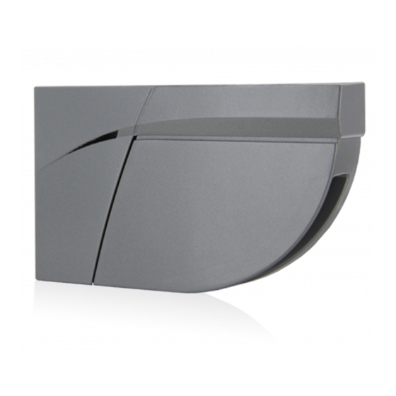
Summary of Contents for BEA LZR FLATSCAN SW
- Page 1 ® DRAFT -FLATSCAN SW SAFETY SENSOR FOR AUTOMATIC SWING DOORS User’s Guide for product version 0200 and higher See product label for serial number...
-
Page 2: Installation
INSTALLATION Do not cover Avoid the presence Avoid moving objects Avoid vibrations. the front screens. and light sources in of smoke and fog in the detection field. the detection field. Avoid condensation. Avoid exposure to Keep the sensor permanently sudden and extreme powered in environments where the temperature can temperature changes. -
Page 3: Led Signals
DESCRIPTION fixation screws (3) mounting base push button master-slave connector main connector hole for master-slave cable clamp (with flexible kit) plug (without flexible kit) flexible kit positioning aids DIP-switch laser head laser window angle adjustment screw cover For optimum safety, install 1 module on each door wing side and interconnect master-slave cable them via the master-slave cable. - Page 4 MOUNTING For optimum safety, install 1 module on each door wing side and interconnect them via the master-slave cable. Remove the cover. Remove the mounting base. Do not hesitate to pull, the cover is very resistant. 5 mm The base has to be attached firmly. Fix the mounting base using the 3 screws.
- Page 5 «click» The sensor has to be attached firmly. Fasten the sensor on the base by sliding the Lock the sensor onto the mounting base by fastening sensor downwards until it clicks. the screw. SLAVE = connected to the master module MASTER = connected to the door controller «click»...
- Page 6 WIRING GREEN 12-24 V DC POWER SUPPLY BROWN YELLOW STOP IMPULSE WHITE Opening side of the door PINK REOPENING IMPULSE GREY Closing side of the door TEST BLUE * Output status when sensor is operational. All wires must be connected. For compliance with EN 16005 and DIN 18650, the door controller test output must be connected and able to test the sensor.
-
Page 7: Service Mode
SERVICE MODE The service mode deactivates the safety detection during 15 minutes and can be useful during an installation, a mechanical teach-in of the door or maintenance work. To enter the service mode, push on the button for at least 2 seconds. To exit the service mode, push again for at least 2 seconds. - Page 8 REMOTE CONTROL SETTINGS (OPTIONAL) DIMENSIONS DOOR WING SAFETY 0.01 4.00 no field 0.01 4.00 no field A teach-in overwrites these values automatically. DIMENSIONS PINCH ZONE SAFETY 0.01 1.50 no field 0.01 4.00 no field DIP 4 = ON A teach-in overwrites these values automatically. MIN.
-
Page 9: Output Configuration
REMOTE CONTROL SETTINGS (OPTIONAL) OUTPUT CONFIGURATION NO POWER NO DETECTION DETECTION NO = normally open / NC = normally closed ANTIMASKING & BACKGROUND ANTIMASKING BACKGROUND Antimasking: protective function which ignores an unwanted object nearby the laser window masking the vision field. Background: reference point in the detection field of the sensor. -
Page 10: How To Use The Remote Control
HOW TO USE THE REMOTE CONTROL After unlocking, the red If the red LED flashes quickly after unlocking, you To end an adjustment session, LED flashes and the sensor need to enter an access code from 1 to 4 digits. always lock the sensor. -
Page 11: Troubleshooting
TROUBLESHOOTING In case of unwanted reactions of the door, verify whether the problem is caused by the sensor or the door controller. To do so, activate the service mode (no safety) and launch a door cycle. If the door cycle is completed successfully, check the sensor. If not, verify the door controller or wiring. The RED or GREEN Launch a new teach-in (closed door). -
Page 12: Technical Specifications
All values measured in specific conditions. BEA SA | LIEGE Science Park | ALLÉE DES NOISETIERS 5 - 4031 ANGLEUR [BELGIUM] | T +32 4 361 65 65 | F +32 4 361 28 58 | INFO@BEA.BE | WWW.BEA-SENSORS.COM BEA hereby declares that the LZR -FLATSCAN SW is in conformity with the basic requirements and the other relevant provisions ®...


Need help?
Do you have a question about the LZR FLATSCAN SW and is the answer not in the manual?
Questions and answers