
Related Manuals for BEA 10LZRWIDESCAN


Summary of Contents for BEA 10LZRWIDESCAN
- Page 1 -WIDESCAN ® MOTION, PRESENCE, AND SAFETY SENSOR FOR INDUSTRIAL DOORS (US VERSION) Visit website for available languages of this document. 75.5916.04 LZR-WIDESCAN 20190913 Page 1 of 16...
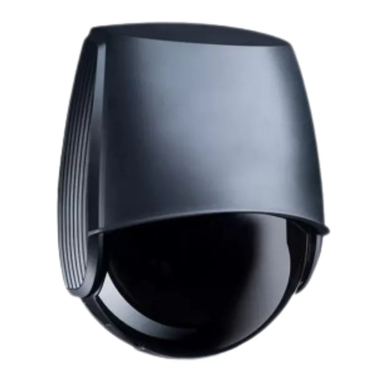
- Page 2 DESCRIPTION main connector protection film laser window LCD screen USB cap 10. keypad LED display 11. tilt angle adjustment screw (1) cover 12. parallel angle adjustment screw (2) cover lock 13. lateral angle lock screw (1) cable passage 14. mounting bracket Page 2 of 16 75.5916.04 LZR-WIDESCAN 20190913...
- Page 3 INSTALLATION & MAINTENANCE TIPS Avoid extreme vibrations. Do not cover the sensor. Avoid moving objects Avoid exposure to sudden and light sources in the and extreme temperature detection field. changes. Keep the protection film Do not use aggressive Avoid direct exposure to It is recommended to during the mounting products to clean the...
- Page 4 BASIC PRINCIPLES: FUNCTIONS & OBJECT There are 3 main functions that create 3 overlapping detection fields, each with certain detection characteristics: SENSOR DETECTS IF: - motion in motion field - certain object type - certain direction SENSOR DETECTS IF: - presence in presence field - certain object type SENSOR DETECTS IF: - presence in safety field...
- Page 5 LED SIGNALS & SYMBOLS LED flashing LED flashing LED flashing LED on LED off LED flashing quickly slowly x times SETTINGS DETECTION All fields Motion detection Unlocked Motion field Pull-cord detection Teach-in status Pull-cord Presence detection Troubleshooting Presence field Safety detection Safety field Factory value (User’s Guide) Factory value (LCD)
-
Page 6: Mounting And Wiring
MOUNTING & WIRING Mounting height: as high as possible (max. 19’6"). The size of the detection field depends on the mounting height. Mounting position: center of door or left corner. Mounting on the right side of the door should be avoided. - Page 7 POSITIONING OF DETECTION FIELD Remove the blue protection film from the laser window. Activate the 2 visible laser spots by pressing twice or pressing on the remote control. Make sure the curtain is parallel to the door by adjusting one or both screws on the side. AWAY When the safety function is required,...
- Page 8 HOW TO ADJUST THE SENSOR BY REMOTE CONTROL To end an adjustment session, After unlocking, the If the red LED flashes quickly after unlocking, enter an always lock the sensor. red LED flashes and the access code from 1 to 4 digits. If you do not know the sensor can be adjusted access code, cycle power.
- Page 9 PROGRAMMING THE SENSOR TEACH-IN: INSTALL - The teach-in zone (i.e. square in front of the 2 visible spots) must be completely clear. - This teach-in must be launched each time a sensor angle has been changed. - Make sure the blue protection film and cover are removed! 10 s 1.
- Page 10 OPTIONAL REMOTE CONTROL SETTINGS Teach-in install cold Presettings standard corridor corner storage The service mode deactivates the presence and safety detection during 15 minutes and can be useful during an installation, a Service Mode mechanical teach-in of the door or maintenance work. Exit the service mode by using the same sequence. full: complete reset of all values Factory Reset full...
- Page 11 OPTIONAL REMOTE CONTROL SETTINGS (cont.) When programming each of the parameters listed below (function, FOR EXAMPLE, if you want the logic, holdtime), you must always enter 3 digits for the given parameter outputs to be Motion (Output 1), Pull- (output 1, output 2, relay). Cord (Output 2), and Safety (relay), 1st digit = Output 1 you must push the following buttons...
- Page 12 OPTIONAL LCD CONTROL SETTINGS The heating function is also available via LCD. This cannot be accessed/programmed via remote control. See the menu path below to access heating values: MAIN QUICK START >MORE OFF (default) AUTO TEACH-IN: PULL-CORD 1.
- Page 13 HEIGHT TRIGGER By default, all objects higher than the selected value will activate the Height Trigger. This function can also be used to partially open the door depending on the height of the object. The Height Trigger function can be used for a door control which has a partial-open input. a.
- Page 14 TEACH-IN: WALK You can also reshape one or more detection fields by walking around the requested field (steps 1 – 3). It is possible to cut into the existing field from the border or to extract a field within the detection field (step 4). Make sure the field is larger than desired.
-
Page 15: Troubleshooting
TROUBLESHOOTING E1: CPU-XXX The sensor encounters an internal Replace sensor. problem E2: XXX PWR The internal power supply is faulty Replace sensor. E2: IN SUPPLY The power supply is too low or too high Verify power supply (Diagnostics > LCD). E2: TEMP The internal temperature is too low or Verify the sensor temperature (Diagnostics >LCD). -
Page 16: Technical Specifications
BEA, Inc. does not guarantee any use of the sensor outside of its intended purpose. BEA, Inc. strongly recommends that installation and service technicians be AAADM-certifi ed for pedestrian doors, IDA-certifi ed for doors/gates, and factory-trained for the type of door/gate system.
Need help?
Do you have a question about the 10LZRWIDESCAN and is the answer not in the manual?
Questions and answers