Table of Contents
Advertisement
Quick Links
Visit website for
available languages
of this document.
2
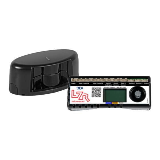
6. Plug-and-Play ports
7. Adjustment knob
8. LCD
9. Hub LEDs
TEACH-IN: Teach-in in progress or required
HOME: Door(s) closed
TRACKING: Door position / Detection zone tracking
75.5753.17 LZR-MICROSCAN T 20200109
75.5753.17 LZR-MICROSCAN T 20200109
1
5
8
LZR-MICROSCAN T
Stand-Alone, Door-Mounted, Safety Sensor
System for Automatic Swing Doors
1. Tilt adjustment
2. Sensor connection ports
3. Sensor LED
3
4. End caps
4
5. Optical window
6
green = operational
red = in detection/monitoring
orange = error (reference hub LCD)
7
9
(US version)
Page 1 of 16
Page 1 of 16
Advertisement
Table of Contents

Related Manuals for BEA LZR-MICROSCAN T


Summary of Contents for BEA LZR-MICROSCAN T
- Page 1 7. Adjustment knob 8. LCD 9. Hub LEDs TEACH-IN: Teach-in in progress or required HOME: Door(s) closed TRACKING: Door position / Detection zone tracking 75.5753.17 LZR-MICROSCAN T 20200109 75.5753.17 LZR-MICROSCAN T 20200109 Page 1 of 16 Page 1 of 16...
-
Page 2: Technical Specifications
BEA, Inc. does not guarantee any use of the sensor outside of its intended purpose. BEA, Inc. strongly recommends that installation and service technicians be AAADM-certifi ed for pedestrian doors, IDA-certifi ed for doors/gates, and factory-trained for the type of door/gate system. -
Page 3: General Installation Tips
READ BEFORE BEGINNING INSTALLATION/PROGRAMMING/SET-UP LZR-MICROSCAN T sensors are intended to be used with PEDESTRIAN, SWING-DOOR systems. PRECAUTIONS Shut off all power going to header before attempting any wiring procedures. ‰ ‰ Maintain a clean and safe environment when working in public areas. -
Page 4: Installation
Refer to Mounting Template 75.5908 when using the Mounting Arm kit. * HOLE SIZE: Be sure to comply with hole sizes called out on the Mounting Template. * LZR-MICROSCAN T SENSORS AND MOUNTING ARM ACCESSORIES ARE HANDED. PLEASE OBSERVE WHEN MOUNTING. - Page 5 Secure the Door Loop to the Master Sensor using the end cap and screws provided. IF NECESSARY, REPEAT THIS SECTION FOR A SECOND DOOR LEAF. DO NOT APPLY COVERS UNTIL THE SYSTEM IS FULLY OPERATIONAL. 75.5753.17 LZR-MICROSCAN T 20200109 75.5753.17 LZR-MICROSCAN T 20200109 Page 5 of 16...
- Page 6 Switches must be wired in series with orange wires of System Harness plugged into hub. NORMAL WIRING WIRING IN SERIES for single doors for simultaneous pairs or dual-egress pairs Page 6 of 16 Page 6 of 16 75.5753.17 LZR-MICROSCAN T 20200109 75.5753.17 LZR-MICROSCAN T 20200109...
- Page 7 STALL COM. EXTERNAL MONITORING LZR-MICROSCAN T hub/sensors are intended to be monitored by the door system (see Application Note #31, 76.0031). If the door control does not utilize monitoring, do not use monitoring wires. When utilizing monitoring, the sensor LED will briefly flash RED during monitoring communication with door control. This indicates that external monitoring is functional.
- Page 8 Plug Power Supply Harness into hub port labeled Power. LZR-MICROSCAN T hub/sensors must be powered by a UL Class 2 power supply limited to 15 W. If a NEMA 5-15R outlet is not available in door header, cut off NEMA 5-15P plug and wire-nut to 110 VAC observing polarity and grounding.
- Page 9 For dual-egress doors, push the right door (Door B) open at least 10 degrees when prompted. continued on next page 75.5753.17 LZR-MICROSCAN T 20200109 75.5753.17 LZR-MICROSCAN T 20200109 Page 9 of 16 Page 9 of 16...
- Page 10 Sensor in detection / Sensor monitoring Orange* Error Sensor in error...reference hub LCD * see TROUBLESHOOTING section for descriptions of orange LED error indications Page 10 of 16 Page 10 of 16 75.5753.17 LZR-MICROSCAN T 20200109 75.5753.17 LZR-MICROSCAN T 20200109...
- Page 11 75.5753.17 LZR-MICROSCAN T 20200109 75.5753.17 LZR-MICROSCAN T 20200109 Page 11 of 16 Page 11 of 16...
- Page 12 Page 12 of 16 Page 12 of 16 75.5753.17 LZR-MICROSCAN T 20200109 75.5753.17 LZR-MICROSCAN T 20200109...
-
Page 13: Troubleshooting
Not using On / Off / Hold Wire existing On / Off / Hold Open switch to jumper or “Hold Open” or “Off” Open Switch plug BEA On / Off / Hold Open Switch into hub. states Hub Environment error Voltage too high/low Verify power supply voltage, power from BEA power supply. - Page 14 If the sensor causes the error, you’ll see an orange blinking LED on that sensor(s) with a number of blinks which correspond with the error type. This error will by displayed on the LZR-MICROSCAN T hub LCD screen as shown (see “Orange Sensor LED Errors”).
- Page 15 Trim and adjust the transfer loop, and then Transfer loop is hanging under sensor(s) perform a new teach-in. Environ Voltage and/or temperature too high/low Install BEA power supply (PN 30.5558). (environmental) EDPS Door moved manually during closed door Automatic Recovery.
- Page 16 Can’t find your answer? Visit www.beainc.com or scan QR code for Frequently Asked Questions! Tech Support & Customer Service: 1-800-523-2462 General Tech Questions: techservices-us@beasensors.com | Tech Docs: www.BEAsensors.com Page 16 of 16 Page 16 of 16 75.5753.17 LZR-MICROSCAN T 20200109 75.5753.17 LZR-MICROSCAN T 20200109...
Need help?
Do you have a question about the LZR-MICROSCAN T and is the answer not in the manual?
Questions and answers