Table of Contents
Advertisement
Available languages
Available languages
Quick Links
Advertisement
Chapters
Table of Contents

Related Manuals for Elektro-Automatik PSI 9000 3U Series


Summary of Contents for Elektro-Automatik PSI 9000 3U Series
- Page 1 Betriebsanleitung PSI 9000 3U DC-Hochleistungs-Netzgerät Achtung! Diese Anleitung gilt nur für Geräte mit TFT-Anzeige und einer Firmware ab „KE: Doc ID: PSI93UTDE 2.24“ (Standard) bzw. „KE: 2.08“ (GPIB), „HMI: 2.14“ und „DR: Revision: 08 1.6.5“. Date: 07/2018...
-
Page 3: Table Of Contents
3.6.1 Begriffsdefinition ..........63 2.3.4 Anschließen an das Stromnetz (AC) ...34 3.6.2 Gerätealarme und Events handhaben ..63 Bedieneinheit (HMI) sperren .......66 www.elektroautomatik.de EA Elektro-Automatik GmbH Telefon: 02162 / 3785-0 Seite 3 Helmholtzstr. 31-37 • 41747 Viersen Telefax: 02162 / 16230 ea1974@elektroautomatik.de... - Page 4 Einleitung ............96 4.3.2 Vorbereitung ..........96 4.3.3 Abgleichvorgang ..........96 Ersatzableitstrommessung nach DIN VDE 0701-1 ..........98 SERVICE & SUPPORT Reparaturen ..........99 Kontaktmöglichkeiten ........99 www.elektroautomatik.de EA Elektro-Automatik GmbH Telefon: 02162 / 3785-0 Seite 4 Helmholtzstr. 31-37 • 41747 Viersen Telefax: 02162 / 16230 ea1974@elektroautomatik.de...
-
Page 5: Allgemeines
Gewährleistung und Garantie Elektro-Automatik garantiert die Funktionsfähigkeit der angewandten Verfahrenstechnik und die ausgewiesenen Leistungsparameter. Die Gewährleistungsfrist beginnt mit der mängelfreien Übergabe. Die Garantiebestimmungen sind den allgemeinen Geschäftsbedingungen (AGB) der EA Elektro-Automatik GmbH zu entnehmen. Haftungsbeschränkungen Alle Angaben und Hinweise in dieser Anleitung wurden unter Berücksichtigung geltender Normen und Vorschrif- ten, des Stands der Technik sowie unserer langjährigen Erkenntnisse und Erfahrungen zusammengestellt. -
Page 6: Entsorgung Des Gerätes
• Ansprüche jeglicher Art wegen Schäden aus nicht bestimmungsgemäßer Verwendung sind ausgeschlossen • Für alle Schäden durch nicht bestimmungsgemäße Verwendung haftet allein der Betreiber www.elektroautomatik.de EA Elektro-Automatik GmbH Telefon: 02162 / 3785-0 Seite 6 Helmholtzstr. 31-37 • 41747 Viersen Telefax: 02162 / 16230... -
Page 7: Sicherheit
• Niemals Netzwerkkabel, die mit dem Ethernet oder dessen Komponenten verbunden sind, in die Master-Slave-Buchsen auf der Rückseite stecken! • Konfigurieren Sie Schutzfunktionen gegen Überspannung usw., die das Gerät für die anzu- schließende Last bietet, stets passend für die jeweilige Anwendung! www.elektroautomatik.de EA Elektro-Automatik GmbH Telefon: 02162 / 3785-0 Seite 7 Helmholtzstr. 31-37 • 41747 Viersen Telefax: 02162 / 16230... -
Page 8: Verantwortung Des Bedieners
Als Fachpersonal gilt, wer aufgrund seiner beruflichen Ausbildung, Kenntnisse und Erfahrungen sowie Kenntnis der einschlägigen Bestimmungen in der Lage ist, die übertragenen Arbeiten ordnungsgemäß auszuführen, mög- liche Gefahren selbständig zu erkennen und Personen- oder Sachschäden zu vermeiden. www.elektroautomatik.de EA Elektro-Automatik GmbH Telefon: 02162 / 3785-0 Seite 8 Helmholtzstr. 31-37 • 41747 Viersen Telefax: 02162 / 16230 ea1974@elektroautomatik.de... -
Page 9: Alarmsignale
Farbiger TFT-Touchscreen mit Gorillaglas, 4.3“, 480 x 272 Punkte, kapazitiv Bedienelemente: 2 Drehknöpfe mit Tastfunktion, 1 Drucktaste Die Nennwerte des Gerätes bestimmen den maximal einstellbaren Bereich. www.elektroautomatik.de EA Elektro-Automatik GmbH Telefon: 02162 / 3785-0 Seite 9 Helmholtzstr. 31-37 • 41747 Viersen Telefax: 02162 / 16230... -
Page 10: Spezifische Technische Daten
(2 RMS-Wert: NF 0...300 kHz, PP-Wert: HF 0...20MHz (3 Typischer Wert bei 100% Ausgangsspannung und 100% Last (4 Der Fehler der Anzeige addiert sich zum Fehler des Istwertes am DC-Ausgang www.elektroautomatik.de EA Elektro-Automatik GmbH Telefon: 02162 / 3785-0 Seite 10 Helmholtzstr. 31-37 • 41747 Viersen Telefax: 02162 / 16230 ea1974@elektroautomatik.de... - Page 11 (1 Bezogen auf den Maximalwert definiert die Genauigkeit die maximale Abweichung zwischen Sollwert und Istwert (2 Technische Daten der Analogschnittstelle siehe „3.5.4.4 Spezifikation der Analogschnittstelle“ auf Seite 60 (3 Artikelnummer der Standardausführung, Geräte mit Optionen abweichend www.elektroautomatik.de EA Elektro-Automatik GmbH Telefon: 02162 / 3785-0 Seite 11 Helmholtzstr. 31-37 • 41747 Viersen Telefax: 02162 / 16230...
- Page 12 (2 RMS-Wert: NF 0...300 kHz, PP-Wert: HF 0...20MHz (3 Typischer Wert bei 100% Ausgangsspannung und 100% Last (4 Der Fehler der Anzeige addiert sich zum Fehler des Istwertes am DC-Ausgang www.elektroautomatik.de EA Elektro-Automatik GmbH Telefon: 02162 / 3785-0 Seite 12 Helmholtzstr. 31-37 • 41747 Viersen Telefax: 02162 / 16230 ea1974@elektroautomatik.de...
- Page 13 (1 Bezogen auf den Maximalwert definiert die Genauigkeit die maximale Abweichung zwischen Sollwert und Istwert (2 Technische Daten der Analogschnittstelle siehe „3.5.4.4 Spezifikation der Analogschnittstelle“ auf Seite 60 (3 Artikelnummer der Standardausführung, Geräte mit Optionen abweichend www.elektroautomatik.de EA Elektro-Automatik GmbH Telefon: 02162 / 3785-0 Seite 13 Helmholtzstr. 31-37 • 41747 Viersen Telefax: 02162 / 16230...
- Page 14 (2 RMS-Wert: NF 0...300 kHz, PP-Wert: HF 0...20MHz (3 Typischer Wert bei 100% Ausgangsspannung und 100% Last (4 Der Fehler der Anzeige addiert sich zum Fehler des Istwertes am DC-Ausgang www.elektroautomatik.de EA Elektro-Automatik GmbH Telefon: 02162 / 3785-0 Seite 14 Helmholtzstr. 31-37 • 41747 Viersen Telefax: 02162 / 16230 ea1974@elektroautomatik.de...
- Page 15 (1 Bezogen auf den Maximalwert definiert die Genauigkeit die maximale Abweichung zwischen Sollwert und Istwert (2 Technische Daten der Analogschnittstelle siehe „3.5.4.4 Spezifikation der Analogschnittstelle“ auf Seite 60 (3 Artikelnummer der Standardausführung, Geräte mit Optionen abweichend www.elektroautomatik.de EA Elektro-Automatik GmbH Telefon: 02162 / 3785-0 Seite 15 Helmholtzstr. 31-37 • 41747 Viersen Telefax: 02162 / 16230...
- Page 16 (2 RMS-Wert: NF 0...300 kHz, PP-Wert: HF 0...20MHz (3 Typischer Wert bei 100% Ausgangsspannung und 100% Last (4 Der Fehler der Anzeige addiert sich zum Fehler des Istwertes am DC-Ausgang www.elektroautomatik.de EA Elektro-Automatik GmbH Telefon: 02162 / 3785-0 Seite 16 Helmholtzstr. 31-37 • 41747 Viersen Telefax: 02162 / 16230 ea1974@elektroautomatik.de...
- Page 17 (1 Bezogen auf den Maximalwert definiert die Genauigkeit die maximale Abweichung zwischen Sollwert und Istwert (2 Technische Daten der Analogschnittstelle siehe „3.5.4.4 Spezifikation der Analogschnittstelle“ auf Seite 60 (3 Artikelnummer der Standardausführung, Geräte mit Optionen abweichend www.elektroautomatik.de EA Elektro-Automatik GmbH Telefon: 02162 / 3785-0 Seite 17 Helmholtzstr. 31-37 • 41747 Viersen Telefax: 02162 / 16230...
- Page 18 (2 RMS-Wert: NF 0...300 kHz, PP-Wert: HF 0...20MHz (3 Typischer Wert bei 100% Ausgangsspannung und 100% Last (4 Der Fehler der Anzeige addiert sich zum Fehler des Istwertes am DC-Ausgang www.elektroautomatik.de EA Elektro-Automatik GmbH Telefon: 02162 / 3785-0 Seite 18 Helmholtzstr. 31-37 • 41747 Viersen Telefax: 02162 / 16230 ea1974@elektroautomatik.de...
- Page 19 (1 Bezogen auf den Maximalwert definiert die Genauigkeit die maximale Abweichung zwischen Sollwert und Istwert (2 Technische Daten der Analogschnittstelle siehe „3.5.4.4 Spezifikation der Analogschnittstelle“ auf Seite 60 (3 Artikelnummer der Standardausführung, Geräte mit Optionen abweichend www.elektroautomatik.de EA Elektro-Automatik GmbH Telefon: 02162 / 3785-0 Seite 19 Helmholtzstr. 31-37 • 41747 Viersen Telefax: 02162 / 16230...
-
Page 20: Ansichten
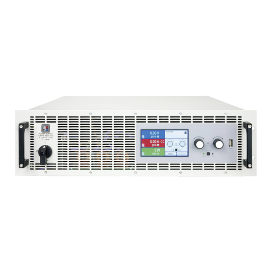
PSI 9000 3U Serie 1.8.4 Ansichten Bild 1 - Vorderseite (Standardausführung) Bild 2 - Rückseite (Standardausführung) www.elektroautomatik.de EA Elektro-Automatik GmbH Telefon: 02162 / 3785-0 Seite 20 Helmholtzstr. 31-37 • 41747 Viersen Telefax: 02162 / 16230 ea1974@elektroautomatik.de... - Page 21 PSI 9000 3U Serie Bild 3 - Vorderseite PSI 9000 Slave Bild 4 - Rückseite PSI 9000 Slave www.elektroautomatik.de EA Elektro-Automatik GmbH Telefon: 02162 / 3785-0 Seite 21 Helmholtzstr. 31-37 • 41747 Viersen Telefax: 02162 / 16230 ea1974@elektroautomatik.de...
- Page 22 PSI 9000 3U Serie www.elektroautomatik.de EA Elektro-Automatik GmbH Telefon: 02162 / 3785-0 Seite 22 Helmholtzstr. 31-37 • 41747 Viersen Telefax: 02162 / 16230 ea1974@elektroautomatik.de...
- Page 23 PSI 9000 3U Serie Bild 7 - Ansicht von oben www.elektroautomatik.de EA Elektro-Automatik GmbH Telefon: 02162 / 3785-0 Seite 23 Helmholtzstr. 31-37 • 41747 Viersen Telefax: 02162 / 16230 ea1974@elektroautomatik.de...
-
Page 24: Bedienelemente
Bedienung oder Fernsteuerung USB Host-Steckplatz Typ A Dient zur Aufnahme handelsüblicher USB-Sticks. Siehe Abschnitt „1.9.6.5. USB-Port (Vorderseite)“ für weitere Informationen. www.elektroautomatik.de EA Elektro-Automatik GmbH Telefon: 02162 / 3785-0 Seite 24 Helmholtzstr. 31-37 • 41747 Viersen Telefax: 02162 / 16230... -
Page 25: Aufbau Und Funktion
Sense Leistungsstufe 1...3 Controller (DR) ≈ ≈ Kommu- HMI (BE) nikation (KE) PSI 9000 2U/3U Blockdiagramm Anybus / GPIB (opt.) www.elektroautomatik.de EA Elektro-Automatik GmbH Telefon: 02162 / 3785-0 Seite 25 Helmholtzstr. 31-37 • 41747 Viersen Telefax: 02162 / 16230 ea1974@elektroautomatik.de... -
Page 26: Lieferumfang
06290367 PSI 9500-90 3U PSI 9750-60 3U Slave 06290368 PSI 9750-60 3U PSI 91500-30 3U Slave 06290369 PSI 91500-30 3U www.elektroautomatik.de EA Elektro-Automatik GmbH Telefon: 02162 / 3785-0 Seite 26 Helmholtzstr. 31-37 • 41747 Viersen Telefax: 02162 / 16230 ea1974@elektroautomatik.de... -
Page 27: Die Bedieneinheit (Hmi)
0-110% Nenn OVP, OCP usw., immer bezogen auf eine Einstellgröße Gilt auch für weitere, auf diese phys. Größe bezogene Werte, wie z. B. OVD zur Spannung oder UCD zum Strom www.elektroautomatik.de EA Elektro-Automatik GmbH Telefon: 02162 / 3785-0 Seite 27 Helmholtzstr. - Page 28 Die Drehknöpfe haben eine Tastfunktion die, überall wo Werte gestellt werden können, zum Verschieben des Cursors von niederwertigen zu höherwertigen Dezimalpositionen (rotierend) des einzustellenden Wertes dient: www.elektroautomatik.de EA Elektro-Automatik GmbH Telefon: 02162 / 3785-0 Seite 28 Helmholtzstr. 31-37 • 41747 Viersen Telefax: 02162 / 16230 ea1974@elektroautomatik.de...
- Page 29 Strom I. pv_record_<nr>.csv Daten der Datenaufzeichnung der erweiterten PV-Funktion nach DIN EN 50530. Siehe „3.10.15.7. Datenaufzeichnung“ für Details www.elektroautomatik.de EA Elektro-Automatik GmbH Telefon: 02162 / 3785-0 Seite 29 Helmholtzstr. 31-37 • 41747 Viersen Telefax: 02162 / 16230 ea1974@elektroautomatik.de...
-
Page 30: Usb-Port Typ B (Rückseite)
Der Eingangsspannungsbereich der Sollwerte bzw. der Ausgangsspannungsbereich der Monitorwerte und der Referenzspannung kann im Einstellungsmenü des Gerätes zwischen 0...5 V und 0...10 V für jeweils 0...100% umgeschaltet werden. www.elektroautomatik.de EA Elektro-Automatik GmbH Telefon: 02162 / 3785-0 Seite 30 Helmholtzstr. 31-37 • 41747 Viersen Telefax: 02162 / 16230 ea1974@elektroautomatik.de... -
Page 31: Share-Bus-Anschluß
Der GPIB-Anschluß dient zur Verbindung zu einem PC bzw. anderen GPIB-Anschlüssen über handelsübliche GPIB-Kabel (gerade oder gewinkelt). Bei Verwendung von gewinkelten Steckern am GPIB-Kabel ist der USB-Anschluß nicht gleichzeitig zugänglich. www.elektroautomatik.de EA Elektro-Automatik GmbH Telefon: 02162 / 3785-0 Seite 31 Helmholtzstr. 31-37 • 41747 Viersen Telefax: 02162 / 16230... -
Page 32: Installation & Inbetriebnahme
• Stellen Sie vor dem Anschließen des Gerätes an die AC-Stromzufuhr sicher, daß die auf dem Typenschild des Gerätes angegebenen Anschlußdaten eingehalten werden. Eine Überspan- nung am AC-Anschluß kann das Gerät beschädigen. www.elektroautomatik.de EA Elektro-Automatik GmbH Telefon: 02162 / 3785-0 Seite 32 Helmholtzstr. 31-37 • 41747 Viersen Telefax: 02162 / 16230 ea1974@elektroautomatik.de... -
Page 33: Vorbereitung
Gerät auch auf jeglicher horizontaler Fläche als Tischgerät betrieben werden kann. Zulässige und unzulässige Aufstellpositionen: Aufstellfläche www.elektroautomatik.de EA Elektro-Automatik GmbH Telefon: 02162 / 3785-0 Seite 33 Helmholtzstr. 31-37 • 41747 Viersen Telefax: 02162 / 16230... -
Page 34: Anschließen An Das Stromnetz (Ac)
Spannungsabfall aufgrund des Leitungswiderstandes. Daher sollte die Netzzuleitung immer so kurz wie möglich gehalten werden. Bild 9 - Beispiel für ein Netzanschlußkabel (nicht im Lieferumfang enthalten) www.elektroautomatik.de EA Elektro-Automatik GmbH Telefon: 02162 / 3785-0 Seite 34 Helmholtzstr. 31-37 • 41747 Viersen Telefax: 02162 / 16230 ea1974@elektroautomatik.de... - Page 35 Vorschläge zur Verteilung der Phasen: Einzelgerät (3,3 kW / 5 kW) Mehrere Geräte (3,3 kW / 5 kW) Mehrere Geräte (6,6 kW / 10 kW) www.elektroautomatik.de EA Elektro-Automatik GmbH Telefon: 02162 / 3785-0 Seite 35 Helmholtzstr. 31-37 • 41747 Viersen Telefax: 02162 / 16230...
-
Page 36: Anschließen Von Dc-Lasten
Typ 1 an der Rückwand des Gerätes. Weiterhin sind in der Abdeckung Typ 1 Ausbrüche (oben, unten, vorn) vorhanden, die nach Bedarf ausgebrochen werden können, um Zuleitungen aus verschiedenen Richtungen zu verlegen. www.elektroautomatik.de EA Elektro-Automatik GmbH Telefon: 02162 / 3785-0 Seite 36 Helmholtzstr. 31-37 • 41747 Viersen Telefax: 02162 / 16230 ea1974@elektroautomatik.de... -
Page 37: Erdung Des Dc-Ausgangs
• (+) Sense darf nur am (+) der Last und (–) Sense nur am (–) der Last angeschlossen werden. Ansonsten können beide Systeme beschädigt werden. • Bei Master-Slave-Betrieb sollte die Fernfühlung nur am Master-Gerät erfolgen www.elektroautomatik.de EA Elektro-Automatik GmbH Telefon: 02162 / 3785-0 Seite 37 Helmholtzstr. 31-37 • 41747 Viersen Telefax: 02162 / 16230 ea1974@elektroautomatik.de... -
Page 38: Installation Eines Schnittstellen-Moduls
Plastiknasen, die auf dem letzten Mil- packt werden, um es her- limeter des Einschubweges auf der grünen auszuziehen. Platine einrasten müssen, damit das Modul auf der Rückwand des Gerätes richtig aufliegt. www.elektroautomatik.de EA Elektro-Automatik GmbH Telefon: 02162 / 3785-0 Seite 38 Helmholtzstr. 31-37 • 41747 Viersen Telefax: 02162 / 16230 ea1974@elektroautomatik.de... -
Page 39: Anschließen Der Analogen Schnittstelle
Falls der oben beschriebene CDC-Treiber auf Ihrem System nicht vorhanden ist oder aus irgendeinem Grund nicht richtig funktionieren sollte, können kommerzielle Anbieter Abhilfe schaffen. Suchen und finden Sie dazu im Internet diverse Anbieter mit den Schlüsselwörtern „cdc driver windows“ oder „cdc driver linux“ oder „cdc driver macos“. www.elektroautomatik.de EA Elektro-Automatik GmbH Telefon: 02162 / 3785-0 Seite 39 Helmholtzstr. 31-37 • 41747 Viersen Telefax: 02162 / 16230 ea1974@elektroautomatik.de... -
Page 40: Erstinbetriebnahme
Aufstockung durch weitere Einheiten. Die Konfiguration des Master-Gerätes, üblicherweise das Gerät mit Anzeige und HMI, kann am Gerät oder per Software erledigt werden, während die Slave-Einheiten nicht extra konfiguriert werden müssen, da bereits als Slave für den Betrieb am Master-Slave-Bus vorkonfiguriert. www.elektroautomatik.de EA Elektro-Automatik GmbH Telefon: 02162 / 3785-0 Seite 40 Helmholtzstr. 31-37 • 41747 Viersen Telefax: 02162 / 16230... -
Page 41: Bedienung Und Verwendung
Beispiel Belastung: die Ausgangsspannung bricht kurz- kurzzeitig über den eingestellten Wert. t = Ausregelzeit zeitig unter den eingestellten Wert ein. t = Ausregelzeit www.elektroautomatik.de EA Elektro-Automatik GmbH Telefon: 02162 / 3785-0 Seite 41 Helmholtzstr. 31-37 • 41747 Viersen Telefax: 02162 / 16230... -
Page 42: Stromregelung / Konstantstrom / Strombegrenzung
) * I Soll Bei aktivierter Innenwiderstandseinstellung, d.h. R-Modus, ist der Funktionsgenerator deaktiviert und der angezeigte Leistungsistwert exkludiert die simulierte Verlustleistung an Ri. www.elektroautomatik.de EA Elektro-Automatik GmbH Telefon: 02162 / 3785-0 Seite 42 Helmholtzstr. 31-37 • 41747 Viersen Telefax: 02162 / 16230... -
Page 43: Alarmzustände
OPP-Schwelle erreicht Diese Schutzfunktion dient nicht dem Schutz des Gerätes, sondern dem Schutz der angeschlossenen Last, falls diese durch zu hohe Leistungsaufnahme beschädigt werden könnte. www.elektroautomatik.de EA Elektro-Automatik GmbH Telefon: 02162 / 3785-0 Seite 43 Helmholtzstr. 31-37 • 41747 Viersen Telefax: 02162 / 16230 ea1974@elektroautomatik.de... -
Page 44: Manuelle Bedienung
Die Menüstruktur ist auf den folgenden Seiten als Schema darge- stellt. Einige Einstellparameter sind selbsterklärend, andere nicht. Diese werden auf den nachfolgenden Seite im Einzelnen erläutert. www.elektroautomatik.de EA Elektro-Automatik GmbH Telefon: 02162 / 3785-0 Seite 44 Helmholtzstr. 31-37 • 41747 Viersen Telefax: 02162 / 16230 ea1974@elektroautomatik.de... - Page 45 PSI 9000 3U Serie www.elektroautomatik.de EA Elektro-Automatik GmbH Telefon: 02162 / 3785-0 Seite 45 Helmholtzstr. 31-37 • 41747 Viersen Telefax: 02162 / 16230 ea1974@elektroautomatik.de...
- Page 46 PSI 9000 3U Serie www.elektroautomatik.de EA Elektro-Automatik GmbH Telefon: 02162 / 3785-0 Seite 46 Helmholtzstr. 31-37 • 41747 Viersen Telefax: 02162 / 16230 ea1974@elektroautomatik.de...
- Page 47 PSI 9000 3U Serie www.elektroautomatik.de EA Elektro-Automatik GmbH Telefon: 02162 / 3785-0 Seite 47 Helmholtzstr. 31-37 • 41747 Viersen Telefax: 02162 / 16230 ea1974@elektroautomatik.de...
- Page 48 Befehl veranlaßtem Beenden der Fernsteuerung sein soll. • AUS = DC-Ausgang ist nach dem Verlassen der Fernsteuerung immer aus • AUTO = Zustand des DC-Ausgangs wird beibehalten www.elektroautomatik.de EA Elektro-Automatik GmbH Telefon: 02162 / 3785-0 Seite 48 Helmholtzstr. 31-37 • 41747 Viersen Telefax: 02162 / 16230 ea1974@elektroautomatik.de...
- Page 49 Bei den Ethernet-Modulen, die zwei Ports haben, bezieht sich „P1“ auf den Port 1 und „P2“ auf den Port 2, so wie am Modul aufgedruckt. Zwei-Port-Module haben nur eine IP. www.elektroautomatik.de EA Elektro-Automatik GmbH Telefon: 02162 / 3785-0 Seite 49 Helmholtzstr.
- Page 50 (Location tag). Max. Länge: 22 Zeichen Datum der Instal- Texteingabefeld zur Eingabe eines beliebigen Textes zum Profibus-Tag „Installationdatum“ lation (Installation date). Max. Länge: 40 Zeichen Beschreib. Texteingabefeld zur Eingabe eines beliebigen Textes zur Beschreibung des Profibus- Slaves. Max. Länge: 54 Zeichen www.elektroautomatik.de EA Elektro-Automatik GmbH Telefon: 02162 / 3785-0 Seite 50 Helmholtzstr. 31-37 • 41747 Viersen Telefax: 02162 / 16230 ea1974@elektroautomatik.de...
- Page 51 Die Baudrate ist einstellbar, weitere serielle Einstellungen sind wie folgt festgelegt: 8 Da- tenbits, 1 Stopbit, Parität = keine Baudrateneinstellungen: 2400, 4800, 9600, 19200, 38400, 57600, 115200 www.elektroautomatik.de EA Elektro-Automatik GmbH Telefon: 02162 / 3785-0 Seite 51 Helmholtzstr. 31-37 • 41747 Viersen Telefax: 02162 / 16230 ea1974@elektroautomatik.de...
- Page 52 Darstellung mit nur Spannung und Strom, plus Status. Siehe auch „3.4.7. Ansichtsmodus der Hauptanzeige wechseln“. Standardeinstellung: beide deaktiviert www.elektroautomatik.de EA Elektro-Automatik GmbH Telefon: 02162 / 3785-0 Seite 52 Helmholtzstr. 31-37 • 41747 Viersen Telefax: 02162 / 16230...
-
Page 53: Einstellgrenzen (Limits)
Leistung auch durch Direkteingabe stellen. Siehe dazu auch 3.4.6. Was das Gerät bei eingeschaltetem Ausgang dann tatsächlich als aktuelle Regelungsart bzw. Betriebsart einstellt, hängt nur von den Sollwerten ab. Mehr Informationen dazu finden Sie in „3.2. Regelungsarten“. www.elektroautomatik.de EA Elektro-Automatik GmbH Telefon: 02162 / 3785-0 Seite 53 Helmholtzstr. 31-37 • 41747 Viersen Telefax: 02162 / 16230 ea1974@elektroautomatik.de... -
Page 54: Sollwerte Manuell Einstellen
Wird ein Wert eingeben, der höher als die jeweilige Einstellgrenze ist, erscheint ein Hinweis und der eingegebene Wert wird auf 0 zurückgesetzt und nicht übernommen. www.elektroautomatik.de EA Elektro-Automatik GmbH Telefon: 02162 / 3785-0 Seite 54 Helmholtzstr. 31-37 • 41747 Viersen Telefax: 02162 / 16230 ea1974@elektroautomatik.de... -
Page 55: Ansichtsmodus Der Hauptanzeige Wechseln
Meßleisten im MENU ein- und ausgeschaltet werden können, sind in „3.4.3.8. Menü „HMI Einstellungen““ zu finden. Normale Statusseite mit Meßleiste Alternative Statusseite mit Meßleiste www.elektroautomatik.de EA Elektro-Automatik GmbH Telefon: 02162 / 3785-0 Seite 55 Helmholtzstr. 31-37 • 41747 Viersen Telefax: 02162 / 16230... -
Page 56: Dc-Ausgang Ein- Oder Ausschalten
Fehler kommen (Stick voll, Stick abgezogen), erscheint ein entsprechendes Symbol . Mit jedem ma- nuellen Stopp oder Ausschalten des DC-Ausgangs wird das Logging beendet und die aufgezeichnete Log-Datei geschlossen. www.elektroautomatik.de EA Elektro-Automatik GmbH Telefon: 02162 / 3785-0 Seite 56 Helmholtzstr. 31-37 • 41747 Viersen Telefax: 02162 / 16230... - Page 57 • Bei Einstellung „Manueller Start/Stopp“ zeichnet das Gerät bei Alarmen weiter auf, damit so z. B. die Dauer von temporären Alarmen wie OT und PF ermittelt werden kann www.elektroautomatik.de EA Elektro-Automatik GmbH Telefon: 02162 / 3785-0 Seite 57 Helmholtzstr. 31-37 • 41747 Viersen Telefax: 02162 / 16230 ea1974@elektroautomatik.de...
-
Page 58: Fernsteuerung
* Für technische Details zu den einzelnen Modulen siehe separate Dokumentation „Programmieranleitung Modbus & SCPI“ Modelle mit installierter Option 3W bieten neben dem USB-Port einen fest installierten GPIB-Anschluß. www.elektroautomatik.de EA Elektro-Automatik GmbH Telefon: 02162 / 3785-0 Seite 58 Helmholtzstr. 31-37 • 41747 Viersen Telefax: 02162 / 16230 ea1974@elektroautomatik.de... -
Page 59: Fernsteuerung Über Analogschnittstelle (As)
• Die Sollwerteingänge VSEL, CSEL, PSEL bzw. RSEL (falls R-Modus aktiviert) dürfen bei Fernsteuerung über die analoge Schnittstelle nicht unbeschaltet bleiben, da sonst schwebend (floating). Sollwerte die nicht gestellt werden sollen können auf einen festen Wert oder auf 100% gelegt werden (Brücke nach VREF oder anders) www.elektroautomatik.de EA Elektro-Automatik GmbH Telefon: 02162 / 3785-0 Seite 59 Helmholtzstr. 31-37 • 41747 Viersen Telefax: 02162 / 16230 ea1974@elektroautomatik.de... - Page 60 *** Nur eins von beiden Signalen möglich, siehe 3.4.3.1 **** Nur während Fernsteuerung ***** Der Fehler eines analogen Pins addiert sich zum allgemeinen Fehler des zugehörigen Wertes am DC-Ausgang des Gerätes www.elektroautomatik.de EA Elektro-Automatik GmbH Telefon: 02162 / 3785-0 Seite 60 Helmholtzstr. 31-37 • 41747 Viersen Telefax: 02162 / 16230 ea1974@elektroautomatik.de...
- Page 61 Einstellung „Analogschnittstelle REM-SB = normal“ entspricht das der Vorgabe „DC-Ausgang einschalten“. Das heißt, sobald mit Pin „REMOTE“ auf Fernsteuerung umgeschaltet wird, schaltet der DC-Ausgang ein! www.elektroautomatik.de EA Elektro-Automatik GmbH Telefon: 02162 / 3785-0 Seite 61 Helmholtzstr. 31-37 • 41747 Viersen Telefax: 02162 / 16230 ea1974@elektroautomatik.de...
- Page 62 Istwerte erfassen Über die AS werden die Ausgangswerte von Strom und Spannung mittels 0...10 V oder 0...5 V abgebildet. Zur Erfassung dienen handelsübliche Multimeter o.ä. www.elektroautomatik.de EA Elektro-Automatik GmbH Telefon: 02162 / 3785-0 Seite 62 Helmholtzstr. 31-37 • 41747 Viersen Telefax: 02162 / 16230 ea1974@elektroautomatik.de...
-
Page 63: Alarme Und Überwachung
OverPower Ausgangsleistung am DC-Ausgang die eingestellte 0 W...1,1*P Digitale Schnitt- Nenn Protection Schwelle erreicht. Außerdem wird der DC-Ausgang stellen ausgeschaltet. www.elektroautomatik.de EA Elektro-Automatik GmbH Telefon: 02162 / 3785-0 Seite 63 Helmholtzstr. 31-37 • 41747 Viersen Telefax: 02162 / 16230 ea1974@elektroautomatik.de... - Page 64 In der nächsten Menüseite das Feld „Alarmton“ berühren. In der Einstellungsseite tippen Sie auf das Symbol, um den Alarmton entweder ein- oder auszuschalten und bestätigen dann mit www.elektroautomatik.de EA Elektro-Automatik GmbH Telefon: 02162 / 3785-0 Seite 64 Helmholtzstr. 31-37 • 41747 Viersen Telefax: 02162 / 16230 ea1974@elektroautomatik.de...
- Page 65 Die Einstellwerte können auch direkt über eine Zehnertastatur eingegeben werden. Diese er- scheint, wenn man auf der jeweiligen Seite, also z. B. „4.1 Event U“, unten auf das Bedienfeld „Direkteingabe“ tippt. www.elektroautomatik.de EA Elektro-Automatik GmbH Telefon: 02162 / 3785-0 Seite 65 Helmholtzstr. 31-37 • 41747 Viersen Telefax: 02162 / 16230 ea1974@elektroautomatik.de...
-
Page 66: Bedieneinheit (Hmi) Sperren
Auf der folgenden Seite betätigen Sie das Bedienfeld „Entsperren“ und werden dann aufgefordert, die vierstellige PIN einzugeben. Deaktivieren Sie die Sperre nach der Eingabe der korrekten PIN mit ENTER. www.elektroautomatik.de EA Elektro-Automatik GmbH Telefon: 02162 / 3785-0 Seite 66 Helmholtzstr. 31-37 • 41747 Viersen Telefax: 02162 / 16230 ea1974@elektroautomatik.de... -
Page 67: Nutzerprofile Laden Und Speichern
In der nun erscheinenden Auswahl (siehe rechts) wählen Sie zwischen Nutzerprofil 1-5 aus, in welches Sie speichern wollen. Das gewählte Nutzerprofil wird daraufhin angezeigt. Sie können hier die Einstellungen und Werte noch einmal kontrollieren, jedoch nicht verändern. Speichern Sie mit Bedienfeld www.elektroautomatik.de EA Elektro-Automatik GmbH Telefon: 02162 / 3785-0 Seite 67 Helmholtzstr. 31-37 • 41747 Viersen Telefax: 02162 / 16230 ea1974@elektroautomatik.de... -
Page 68: Der Funktionsgenerator
Funktionen, wie Rechteck oder Sinus, aus. Alternativ kann am DC- Ausgang mit einer zusätzlichen Last (fest & ohmsch oder elektronisch & variabel) die Abfallzeit beim Signalverlauf verbessert werden. www.elektroautomatik.de EA Elektro-Automatik GmbH Telefon: 02162 / 3785-0 Seite 68 Helmholtzstr. 31-37 • 41747 Viersen Telefax: 02162 / 16230 ea1974@elektroautomatik.de... -
Page 69: Arbeitsweise
Legen Sie unbedingt noch die Grenzwerte für U, I und P im Bildschirm fest, den Sie mit errei- chen. Die Einstellungen der einzelnen Funktionen sind weiter unten beschrieben. www.elektroautomatik.de EA Elektro-Automatik GmbH Telefon: 02162 / 3785-0 Seite 69 Helmholtzstr. 31-37 • 41747 Viersen Telefax: 02162 / 16230... -
Page 70: Sinus-Funktion
100 V und sin(I) die Amplitude auf 30 A ein, bei einem Offset von 50 A. Die sich ergebende max. Leistung bei Erreichen des höchsten Punktes der Sinuskurve wäre dann (30 A + 50 A) * 100 V = 8000 W. www.elektroautomatik.de EA Elektro-Automatik GmbH Telefon: 02162 / 3785-0 Seite 70 Helmholtzstr. 31-37 • 41747 Viersen Telefax: 02162 / 16230... -
Page 71: Dreieck-Funktion
Puls ergäben sich dann bei 80% Duty cycle t1 = 40 ms*0,8 = 32 ms. Die Zeit t2 wäre dann mit 8 ms zu setzen. www.elektroautomatik.de EA Elektro-Automatik GmbH Telefon: 02162 / 3785-0 Seite 71 Helmholtzstr. 31-37 • 41747 Viersen Telefax: 02162 / 16230 ea1974@elektroautomatik.de... -
Page 72: Trapez-Funktion
Prüfimpulse nachgebildet werden. Soll die Kurve in Sequenzpunkt 4 einen Sinus enthalten, so müßte sie alternativ mit dem Arbiträrgenerator erzeugt werden. Sequenzpunkte www.elektroautomatik.de EA Elektro-Automatik GmbH Telefon: 02162 / 3785-0 Seite 72 Helmholtzstr. 31-37 • 41747 Viersen Telefax: 02162 / 16230... -
Page 73: Arbiträr-Funktion
1 s und die Frequenz 1 Hz, entstünde genau 1 Sinuswelle. Wäre bei gleicher Frequenz die Zeit nur 0,5 s, entstünde nur eine Sinushalbwelle. Seq.Zeit www.elektroautomatik.de EA Elektro-Automatik GmbH Telefon: 02162 / 3785-0 Seite 73 Helmholtzstr. 31-37 • 41747 Viersen Telefax: 02162 / 16230... - Page 74 Einstellung der DC-Werte. Diese sind hier bei Start und Ende ungleich. Generiert wird eine Rampe mit ansteigendem Verlauf. Seq.Zeit www.elektroautomatik.de EA Elektro-Automatik GmbH Telefon: 02162 / 3785-0 Seite 74 Helmholtzstr. 31-37 • 41747 Viersen Telefax: 02162 / 16230...
- Page 75 Punkt 3: Horizontale Rampe (f = 0) Punkt 4: Abfallende Rampe (f = 0) Punkt 1 Punkt 2 Pkt. 3 Punkt 4 www.elektroautomatik.de EA Elektro-Automatik GmbH Telefon: 02162 / 3785-0 Seite 75 Helmholtzstr. 31-37 • 41747 Viersen Telefax: 02162 / 16230 ea1974@elektroautomatik.de...
- Page 76 . Die gewählte Datei wird nun überprüft und, sofern in Ordnung, geladen. Bei Formatfehlern wird eine entsprechende Meldung angezeigt. Dann muß die Datei korrigiert und der Vorgang wiederholt werden. www.elektroautomatik.de EA Elektro-Automatik GmbH Telefon: 02162 / 3785-0 Seite 76 Helmholtzstr. 31-37 • 41747 Viersen Telefax: 02162 / 16230 ea1974@elektroautomatik.de...
-
Page 77: Rampen-Funktion
Spannungswerte interpretiert, selbst wenn sie vom Anwender als Stromwerte berechnet und dann fälschlicherweise als UI-Tabelle geladen wurden. Diese Funktion eignet sich am besten zur Simulation von Brennstoffzellen. www.elektroautomatik.de EA Elektro-Automatik GmbH Telefon: 02162 / 3785-0 Seite 77 Helmholtzstr. 31-37 • 41747 Viersen Telefax: 02162 / 16230... - Page 78 Laden Sie die Funktion mit , um Sie dann zu starten und zu bedienen wie gewohnt (siehe auch „3.10.4.1. Auswahl und Steuerung einer Funktion“). www.elektroautomatik.de EA Elektro-Automatik GmbH Telefon: 02162 / 3785-0 Seite 78 Helmholtzstr. 31-37 • 41747 Viersen Telefax: 02162 / 16230...
-
Page 79: Pv-Tabellenfunktion (Photovoltaik)
Lichtsituation des Solarpanels zwischen totaler Dunkelheit Umpp (0%) und minimaler Lichtfülle (100%) darstellt, die das Solarpanel benötigt um die max. Leistung zu liefern. www.elektroautomatik.de EA Elektro-Automatik GmbH Telefon: 02162 / 3785-0 Seite 79 Helmholtzstr. 31-37 • 41747 Viersen Telefax: 02162 / 16230... -
Page 80: Fc-Tabellenfunktion (Brennstoffzelle)
Strom ansteigen. Sollten die genannten Regeln nicht eingehalten werden, erscheint eine Fehlermeldung und die eingegebenen Werte werden auf 0 zurückgesetzt. www.elektroautomatik.de EA Elektro-Automatik GmbH Telefon: 02162 / 3785-0 Seite 80 Helmholtzstr. 31-37 • 41747 Viersen Telefax: 02162 / 16230... - Page 81 Die Ausgangsspannung stellt sich in Abhängigkeit vom Ausgangsstrom ein, der durch die angelegte variable Last definiert wird und nimmt mit steigendem Strom ab. Ohne Last geht die Spannung auf den Wert Uoc. Stoppen Sie jederzeit wie in 3.10.4.1 beschrieben. www.elektroautomatik.de EA Elektro-Automatik GmbH Telefon: 02162 / 3785-0 Seite 81 Helmholtzstr. 31-37 • 41747 Viersen Telefax: 02162 / 16230...
-
Page 82: Erweiterte Pv-Tabellenfunktion Nach Din En 50530
Zeit. Modus TAG E/T Automatisch ablaufende Simulation. Ein Tagesverlauf aus bis zu 100.000 Stützpunkten, be- stehend aus Vorgaben für Bestrahlungsstärke, Temperatur und Zeit. www.elektroautomatik.de EA Elektro-Automatik GmbH Telefon: 02162 / 3785-0 Seite 82 Helmholtzstr. 31-37 • 41747 Viersen Telefax: 02162 / 16230... - Page 83 Zwischenpunkt eine eigene Verweildauer zwischen 500 ms und 999 ms haben kann. • Die Zwischenwerte berücksichtigen selbstverständlich auch die Steigung zwischen dem aktuellen und dem folgenden Stützpunkt und somit erhält jeder Zwischenwert eine entsprechende Wertänderung. www.elektroautomatik.de EA Elektro-Automatik GmbH Telefon: 02162 / 3785-0 Seite 83 Helmholtzstr. 31-37 • 41747 Viersen Telefax: 02162 / 16230 ea1974@elektroautomatik.de...
- Page 84 Parameter „Logging mit Einheit (V, A, W)“ in den allgemeinen Einstellungen im MENU gewählt werden, sowie über Parameter „USB Trennzeichen-Format“ auch das Trennzeichen- und De- zimalzeichenformat der CSV-Datei. www.elektroautomatik.de EA Elektro-Automatik GmbH Telefon: 02162 / 3785-0 Seite 84 Helmholtzstr. 31-37 • 41747 Viersen Telefax: 02162 / 16230 ea1974@elektroautomatik.de...
- Page 85 Format (siehe 3.10.15.5) Tagesverlauf-Stützpunkte (1-100.000) in das Gerät geladen werden. Außerdem kann wahlweise die Interpolation (siehe 3.10.15.6) akti- viert werden. www.elektroautomatik.de EA Elektro-Automatik GmbH Telefon: 02162 / 3785-0 Seite 85 Helmholtzstr. 31-37 • 41747 Viersen Telefax: 02162 / 16230 ea1974@elektroautomatik.de...
- Page 86 Man erhält durch das Auslesen bis zu 4096 Stromwerte. Die Visualisierung der Tabellendaten in einem XY-Diagramm in z. B. Excel zeigt die berechnete Form auf. www.elektroautomatik.de EA Elektro-Automatik GmbH Telefon: 02162 / 3785-0 Seite 86 Helmholtzstr. 31-37 • 41747 Viersen Telefax: 02162 / 16230 ea1974@elektroautomatik.de...
-
Page 87: Fernsteuerung Des Funktionsgenerators
• Der Funktionsgenerator ist nicht verfügbar, wenn Geräte im Widerstands-Betrieb (R-Modus) arbeiten • Einige Funktionen basieren auf dem Arbiträrgenerator, andere auf dem XY-Generator. Daher sind beide getrennt zu bedienen www.elektroautomatik.de EA Elektro-Automatik GmbH Telefon: 02162 / 3785-0 Seite 87 Helmholtzstr. 31-37 • 41747 Viersen Telefax: 02162 / 16230 ea1974@elektroautomatik.de... -
Page 88: Weitere Anwendungen
Der Share-Bus ist gepolt. Achten Sie auf polrichtige Verkabelung! • Die Verwendung des Share-Bus‘ bedingt zumindest die Verbindung der DC-Minus-Aus- gänge der Geräte als Bezugspunkt. www.elektroautomatik.de EA Elektro-Automatik GmbH Telefon: 02162 / 3785-0 Seite 88 Helmholtzstr. 31-37 • 41747 Viersen Telefax: 02162 / 16230... - Page 89 Verbinden Sie das Slave-Gerät über den rückseitigen USB-Port oder eine Ethernet-Schnittstelle mit einem PC. Starten Sie die Software EA Power Control und lassen Sie die Software das Gerät finden. Öffnen Sie die App „Settings“ für das Gerät und stellen Sie im Reiter „Master-Slave“ den Parameter „Master- Slave-Modus“ auf „SLAVE“. Das Slave-Gerät ist hiermit fertig konfiguriert. Für jedes weitere Slave-Gerät genauso wiederholen. www.elektroautomatik.de EA Elektro-Automatik GmbH Telefon: 02162 / 3785-0 Seite 89 Helmholtzstr. 31-37 • 41747 Viersen Telefax: 02162 / 16230 ea1974@elektroautomatik.de...
- Page 90 Um alle diese Werte nach dem Verlassen des MS-Betriebs schnell wieder herstellen zu können, wird die Verwendung von Nutzerprofilen empfohlen (siehe „3.9. Nutzerprofile laden und speichern“) www.elektroautomatik.de EA Elektro-Automatik GmbH Telefon: 02162 / 3785-0 Seite 90 Helmholtzstr. 31-37 • 41747 Viersen Telefax: 02162 / 16230 ea1974@elektroautomatik.de...
- Page 91 System arbeiten soll erforderlich sein, bei den inaktiven Einheiten den Share-Bus-Stecker abzuziehen, weil sie auch im ausgeschaltetem Zustand durch ihre Impedanz auf den Share-Bus wirken und ihn negativ beeinflussen könnten. www.elektroautomatik.de EA Elektro-Automatik GmbH Telefon: 02162 / 3785-0 Seite 91 Helmholtzstr. 31-37 • 41747 Viersen Telefax: 02162 / 16230 ea1974@elektroautomatik.de...
-
Page 92: Reihenschaltung
Folgendes gilt es zu beachten: • Kein Verpolungsschutz! Das Gerät wird durch eine verpolt angeschlossene Batterie beschädigt, auch wenn es nicht eingeschaltet ist. www.elektroautomatik.de EA Elektro-Automatik GmbH Telefon: 02162 / 3785-0 Seite 92 Helmholtzstr. 31-37 • 41747 Viersen Telefax: 02162 / 16230... -
Page 93: Zwei-Quadranten-Betrieb (2Qb)
Share-Bus verbunden, wobei sich die Anzahl auf max. 16 Ge- räte begrenzt. Lasten sind im 2QB immer Slaves am Sharebus, sowie eins der PSUs Master. www.elektroautomatik.de EA Elektro-Automatik GmbH Telefon: 02162 / 3785-0 Seite 93 Helmholtzstr. 31-37 • 41747 Viersen Telefax: 02162 / 16230 ea1974@elektroautomatik.de... - Page 94 Batteriespannung. Bei Erreichen von 27 V wird das Netzgerät nur noch den Erhaltungsladestrom für die Batterie liefern. www.elektroautomatik.de EA Elektro-Automatik GmbH Telefon: 02162 / 3785-0 Seite 94 Helmholtzstr. 31-37 • 41747 Viersen Telefax: 02162 / 16230 ea1974@elektroautomatik.de...
-
Page 95: Instandhaltung & Wartung
Applikationen mit sich bringen. Es wird empfohlen, die Firmware-Historie in Hinsicht auf Änderungen genauestens durchzulesen • Bei neuen Funktionen ist eine aktualisierte Dokumentation (Handbuch und/oder Programmieranleitung, sowie LabView VIs) teils erst viel später verfügbar www.elektroautomatik.de EA Elektro-Automatik GmbH Telefon: 02162 / 3785-0 Seite 95 Helmholtzstr. 31-37 • 41747 Viersen Telefax: 02162 / 16230... -
Page 96: Nachjustierung (Kalibrierung)
Die Erläuterung des Abgleichvorgangs erfolgt anhand des Beispiel-Modells PSI 9080-170 3U. Andere Modelle sind auf gleiche Weise zu behandeln, mit entsprechenden Werten für Spannung und Strom des Netzgerätes. www.elektroautomatik.de EA Elektro-Automatik GmbH Telefon: 02162 / 3785-0 Seite 96 Helmholtzstr. 31-37 • 41747 Viersen Telefax: 02162 / 16230 ea1974@elektroautomatik.de... - Page 97 Anzeige dazu aufgefordert. Bitte beachten Sie, den angezeigten Meßwert immer erst nach etwa mindestens 2 Sekunden zu bestätigen, weil eine Einpendelung des Meßwertes gewartet wird. www.elektroautomatik.de EA Elektro-Automatik GmbH Telefon: 02162 / 3785-0 Seite 97 Helmholtzstr. 31-37 • 41747 Viersen Telefax: 02162 / 16230 ea1974@elektroautomatik.de...
-
Page 98: Ersatzableitstrommessung Nach Din Vde 0701-1
Hinweis: Das Bild unten zeigt das Meßverfahren für zweiphasige Netzanschlüsse. Bei einem Drehstromgerät wird Netzeingang Phase N dann durch L2 und/oder L3 ersetzt. www.elektroautomatik.de EA Elektro-Automatik GmbH Telefon: 02162 / 3785-0 Seite 98 Helmholtzstr. 31-37 • 41747 Viersen Telefax: 02162 / 16230... -
Page 99: Service & Support
Bei Fragen und Problemen mit dem Betrieb des Gerätes, Verwendung von optionalen Komponenten, mit der Do- kumentation oder Software kann der technische Support telefonisch oder per E-Mail kontaktiert werden. Adressen E-Mailadressen Telefonnummern EA Elektro-Automatik GmbH Technischer Support: Zentrale: 02162 / 37850 Helmholtzstr. 31-37 support@elektroautomatik.de... - Page 100 PSI 9000 3U Serie www.elektroautomatik.de EA Elektro-Automatik GmbH Telefon: 02162 / 3785-0 Seite 100 Helmholtzstr. 31-37 • 41747 Viersen Telefax: 02162 / 16230 ea1974@elektroautomatik.de...
- Page 102 EA Elektro-Automatik GmbH & Co. KG Entwicklung - Produktion - Vertrieb Helmholtzstraße 31-37 41747 Viersen Telefon: 02162 / 37 85-0 Telefax: 02162 / 16 230 E-Mail: ea1974@elektroautomatik.de Internet: www.elektroautomatik.de...
- Page 103 Operating Guide PSI 9000 3U DC High Efficiency Power Supply Attention! This document is only valid for devices with TFT display and firmware “KE: 2.24” Doc ID: PSI93UTEN (standard models) resp. “KE: 2.08” (GPIB models), “HMI: Revision: 08 2.14” and “DR: 1.6.5” or higher. Date: 08/2018...
- Page 105 PSI 9000 3U Series TABLE OF CONTENTS GENERAL About this document ........5 2.3.5 Connection to DC loads .......45 1.1.1 Retention and use ..........5 2.3.6 Grounding of the DC output ......46 1.1.2 Copyright ............5 2.3.7 Connecting the analog interface ....46 1.1.3 Validity ............5...
- Page 106 PSI 9000 3U Series 3.10.2 General ............75 3.10.3 Method of operation ........76 3.10.4 Manual operation .........76 3.10.5 Sine wave function ........77 3.10.6 Triangular function ........78 3.10.7 Rectangular function ........78 3.10.8 Trapezoidal function ........79 3.10.9 DIN 40839 function ........79 3.10.10 Arbitrary function ..........80 3.10.11 Ramp function ..........84...
-
Page 107: General
EA Elektro-Automatik guarantees the functional competence of the applied technology and the stated performance parameters. The warranty period begins with the delivery of free from defects equipment. Terms of guarantee are included in the general terms and conditions (TOS) of EA Elektro-Automatik. Limitation of liability All statements and instructions in this manual are based on current norms and regulations, up-to-date technology and our long term knowledge and experience. -
Page 108: Disposal Of Equipment
PSI 9000 3U Series Disposal of equipment A piece of equipment which is intended for disposal must, according to European laws and regulations (ElektroG, WEEE) be returned to the manufacturer for scrapping, unless the person operating the piece of equipment or another, delegated person is conducting the disposal. -
Page 109: Safety
PSI 9000 3U Series Safety 1.7.1 Safety notices Mortal danger - Hazardous voltage • Electrical equipment operation means that some parts can be under dangerous voltage. Therefore all parts under voltage must be covered! This basically applies to all models, though 40 V models according to SELV can’t generate hazardous DC voltage. -
Page 110: Responsibility Of The User
PSI 9000 3U Series 1.7.2 Responsibility of the user The equipment is in industrial operation. Therefore the operators are governed by the legal safety regulations. Alongside the warning and safety notices in this manual the relevant safety, accident prevention and environmental regulations must also be applied. -
Page 111: Alarm Signals
PSI 9000 3U Series 1.7.5 Alarm signals The equipment offers various possibilities for signalling alarm conditions, however, not for danger situations. The signals may be optical (on the display as text), acoustic (piezo buzzer) or electronic (status output of the analog interface). -
Page 112: Specific Technical Data (400 V Ac Models)
PSI 9000 3U Series 1.8.3 Specific technical data (400 V AC models) Model 3.3 kW / 5 kW PSI 9040-170 PSI 9080-170 PSI 9200-70 PSI 9360-40 PSI 9500-30 AC Input Voltage (L-L), Frequency 340...460 V AC, 45 - 65 Hz... - Page 113 PSI 9000 3U Series Model 3.3 kW / 5 kW PSI 9040-170 PSI 9080-170 PSI 9200-70 PSI 9360-40 PSI 9500-30 Internal resistance regulation Adjustment range 0...7 Ω 0...14 Ω 0...85 Ω 0...270 Ω 0...500 Ω Accuracy ≤2% of max. resistance ± 0.3% of rated current Display: Resolution See section „1.9.6.4.
- Page 114 PSI 9000 3U Series Model 5 kW / 6.6 kW / 10 kW PSI 9750-20 PSI 9040-340 PSI 9040-510 PSI 9080-340 PSI 9200-140 AC Input Voltage (L-L) 340...460 V AC Connection 2ph,PE 3ph,PE 3ph,PE 3ph,PE 3ph,PE Frequency 45 - 65 Hz...
- Page 115 PSI 9000 3U Series Model 5 kW / 6.6 kW / 10 kW PSI 9750-20 PSI 9040-340 PSI 9040-510 PSI 9080-340 PSI 9200-140 Internal resistance regulation Adjustment range 0...1125 Ω 0...3,5 Ω 0...2 Ω 0...7 Ω 0...42 Ω Accuracy ≤2% of max. resistance ± 0.3% of rated current Display: Resolution See section „1.9.6.4.
- Page 116 PSI 9000 3U Series Model 10 kW / 15 kW PSI 9360-80 PSI 9500-60 PSI 9750-40 PSI 91000-30 PSI 9080-510 AC Input Voltage (L-L) 340...460 V AC Connection 3ph,PE 3ph,PE 3ph,PE 3ph,PE 3ph,PE Frequency 45 - 65 Hz 45 - 65 Hz...
- Page 117 PSI 9000 3U Series Model 10 kW / 15 kW PSI 9360-80 PSI 9500-60 PSI 9750-40 PSI 91000-30 PSI 9080-510 Internal resistance regulation Adjustment range 0...135 Ω 0...250 Ω 0...562 Ω 0...1000 Ω 0...5 Ω Accuracy ≤2% of max. resistance ± 0.3% of rated current Display: Resolution See section „1.9.6.4.
- Page 118 PSI 9000 3U Series Model 15 kW PSI 9200-210 PSI 9360-120 PSI 9500-90 AC Input Voltage (L-L) 340...460 V AC Connection 3ph,PE 3ph,PE 3ph,PE Frequency 45 - 65 Hz 45 - 65 Hz 45 - 65 Hz Fusing (internal) 6x T16 A...
- Page 119 PSI 9000 3U Series Model 15 kW PSI 9200-210 PSI 9360-120 PSI 9500-90 Internal resistance regulation Adjustment range 0...28 Ω 0...90 Ω 0...166 Ω Accuracy ≤2% of max. resistance ± 0.3% of rated current Display: Resolution See section „1.9.6.4. Resolution of the displayed values“...
- Page 120 PSI 9000 3U Series Model 15 kW PSI 9750-60 PSI 91000-40 PSI 91500-30 AC Input Voltage (L-L) 340...460 V AC Connection 3ph,PE 3ph,PE 3ph,PE Frequency 45 - 65 Hz 45 - 65 Hz 45 - 65 Hz Fusing (internal) 6x T16 A...
- Page 121 PSI 9000 3U Series Model 15 kW PSI 9750-60 PSI 91000-40 PSI 91500-30 Internal resistance regulation Adjustment range 0...375 Ω 0...810 Ω 0...1500 Ω Accuracy ≤2% of max. resistance ± 0.3% of rated current Display: Resolution See section „1.9.6.4. Resolution of the displayed values“...
-
Page 122: Specific Technical Data (208 V Ac Models)
PSI 9000 3U Series 1.8.4 Specific technical data (208 V AC models) Model 5 kW PSI 9080-170 PSI 9200-70 PSI 9360-40 PSI 9500-30 PSI 9750-20 AC Input Voltage (L-L), Frequency 208 V, ± 10%, 45 - 65 Hz Connection 2ph,PE... - Page 123 PSI 9000 3U Series Model 5 kW PSI 9080-170 PSI 9200-70 PSI 9360-40 PSI 9500-30 PSI 9750-20 Internal resistance regulation Adjustment range 0...14 Ω 0...85 Ω 0...270 Ω 0...500 Ω 0...1125 Ω Accuracy ≤2% of max. resistance ± 0.3% of rated current Display: Resolution See section „1.9.6.4.
- Page 124 PSI 9000 3U Series Model 10 kW PSI 9080-340 PSI 9200-140 PSI 9360-80 PSI 9500-60 PSI 9750-40 AC Input Voltage (L-L) 208 V, ± 10% Connection 3ph,PE 3ph,PE 3ph,PE 3ph,PE 3ph,PE Frequency 45 - 65 Hz 45 - 65 Hz...
- Page 125 PSI 9000 3U Series Model 10 kW PSI 9080-340 PSI 9200-140 PSI 9360-80 PSI 9500-60 PSI 9750-40 Internal resistance regulation Adjustment range 0...7 Ω 0...42 Ω 0...135 Ω 0...250 Ω 0...562 Ω Accuracy ≤2% of max. resistance ± 0.3% of rated current Display: Resolution See section „1.9.6.4.
- Page 126 PSI 9000 3U Series Model 10 kW / 15 kW PSI 91000-30 PSI 9080-510 PSI 9200-210 PSI 9360-120 PSI 9500-90 AC Input Voltage (L-L) 208 V, ± 10% Connection 3ph,PE 3ph,PE 3ph,PE 3ph,PE 3ph,PE Frequency 45 - 65 Hz 45 - 65 Hz...
- Page 127 PSI 9000 3U Series Model 10 kW / 15 kW PSI 91000-30 PSI 9080-510 PSI 9200-210 PSI 9360-120 PSI 9500-90 Internal resistance regulation Adjustment range 0...1000 Ω 0...5 Ω 0...28 Ω 0...90 Ω 0...166 Ω Accuracy ≤2% of max. resistance ± 0.3% of rated current Display: Resolution See section „1.9.6.4.
- Page 128 PSI 9000 3U Series Model 15 kW PSI 9750-60 PSI 91000-40 PSI 91500-30 AC Input Voltage (L-L) 208 V, ± 10% Connection 3ph,PE 3ph,PE 3ph,PE Frequency 45 - 65 Hz 45 - 65 Hz 45 - 65 Hz Fusing (internal)
- Page 129 PSI 9000 3U Series Model 15 kW PSI 9750-60 PSI 91000-40 PSI 91500-30 Internal resistance regulation Adjustment range 0...375 Ω 0...810 Ω 0...1500 Ω Accuracy ≤2% of max. resistance ± 0.3% of rated current Display: Resolution See section „1.9.6.4. Resolution of the displayed values“...
-
Page 130: Views
PSI 9000 3U Series 1.8.5 Views Figure 1 - Front view Figure 2 - Rear view (standard version) EA Elektro-Automatik GmbH Fon: +49 2162 / 3785-0 www.elektroautomatik.de Page 28 Helmholtzstr. 31-37 • 41747 Viersen Fax: +49 2162 / 16230 ea1974@elektroautomatik.de... - Page 131 PSI 9000 3U Series Figure 3 - Front view (PSI 9000 Slave) Figure 4 - Rear view (PSI 9000 Slave) EA Elektro-Automatik GmbH Fon: +49 2162 / 3785-0 www.elektroautomatik.de Page 29 Helmholtzstr. 31-37 • 41747 Viersen Fax: +49 2162 / 16230 ea1974@elektroautomatik.de...
- Page 132 PSI 9000 3U Series EA Elektro-Automatik GmbH Fon: +49 2162 / 3785-0 www.elektroautomatik.de Page 30 Helmholtzstr. 31-37 • 41747 Viersen Fax: +49 2162 / 16230 ea1974@elektroautomatik.de Germany...
- Page 133 PSI 9000 3U Series Figure 7 - View from above (EU model shown) EA Elektro-Automatik GmbH Fon: +49 2162 / 3785-0 www.elektroautomatik.de Page 31 Helmholtzstr. 31-37 • 41747 Viersen Fax: +49 2162 / 16230 ea1974@elektroautomatik.de Germany...
-
Page 134: Control Elements
PSI 9000 3U Series 1.8.6 Control elements Figure 8- Control Panel Overview of the elements on the control panel For a detailed description see section „1.9.6. The control panel (HMI)“. Touchscreen display Used for selection of set values, menus and settings, as well as display of actual values and status. -
Page 135: Construction And Function
1.9.1 General description The electronic high performance power supplies of the PSI 9000 3U series are especially suitable for test systems and industrial controls due to their compact construction in a 19” enclosure with 3 height units (3U). Apart from basic functions of power supplies, set point curves can be generated in the integrated function generator (sine, rectangular, triangular and other curve types). -
Page 136: Scope Of Delivery
PSI 9000 3U Series 1.9.3 Scope of delivery 1 x Power supply device 1 x Share Bus plug 1 x Remote sensing plug 1 x 1.8 m USB cable 1 x Set of DC terminal covers 1 x Share/Sense terminal cover (only with models from 750 V) -
Page 137: The Control Panel (Hmi)
PSI 9000 3U Series 1.9.6 The control panel (HMI) The HMI (Human Machine Interface) consists of a display with touchscreen, two rotary knobs, a pushbutton and an USB port. 1.9.6.1 Touchscreen display The graphic touchscreen display is divided into a number of areas. The complete display is touch sensitive and can be operated by finger or stylus to control the equipment. - Page 138 PSI 9000 3U Series • Status display (upper right) This area displays various status texts and symbols: Display Description Locked The HMI is locked Unlocked The HMI is unlocked Remote: The device is under remote control from..Analog ..the built-in analog interface USB &...
- Page 139 PSI 9000 3U Series 1.9.6.4 Resolution of the displayed values In the display, set values can be adjusted in fixed increments. The number of decimal places depends on the device model. The values have 3 to 5 digits. Actual and set values always have the same number of digits.
-
Page 140: Usb Port Type B (Rear Side)
PSI 9000 3U Series 1.9.7 USB port type B (rear side) The USB-B port on the back side of the device is provided for communication with the de- vice and for firmware updates. The included USB cable can be used to connect the device to a PC (USB 2.0 or 3.0). -
Page 141: Share" Connector
PSI 9000 3U Series 1.9.10 “Share” connector The 2 pole WAGO socket (“Share”) on the back side of the device is provided for connection to equally named sockets on compatible power supplies series to achieve a balanced load current distribution during parallel connection. The socket is also used to connect the power supply to compatible electronic loads, in order to build a two-quadrants operation setup. -
Page 142: Installation & Commissioning
Preparation Mains connection for the PSI 9000 3U series is done via the included 5 pole plug on the back of the device. Wiring of the plug is at least 3 strand (L2+L3+PE) or, for some models, 4 strand (L1+L2+L3+PE) of suitable cross section and length. -
Page 143: Installing The Device
PSI 9000 3U Series 2.3.3 Installing the device • Select the location for the device so that the connection to the load is as short as possible. • Leave sufficient space behind the equipment, minimum 30cm, for ventilation. A device in a 19” housing will usually be mounted on suitable rails and installed in 19” racks or cabinets. The depth of the device and its weight must be taken into account. -
Page 144: Connection To Ac Supply
PSI 9000 3U Series 2.3.4 Connection to AC supply • Connection to an AC mains supply may only be carried out by qualified personnel! • Cable cross section must be suitable for the maximum input current of the device (see tables below)! • Before plugging in the input plug ensure that the device is switched off by its mains switch! - Page 145 PSI 9000 3U Series 2.3.4.2 Models for 208 V The 208 V models are delivered with a 4 pole mains plug for higher currents. Depending on model, the device requires a supply with 2 or 3 phases and 208 V, which have to be wired according to the labelling on the plug.
- Page 146 PSI 9000 3U Series 2.3.4.3 Strain relief and plug fixture There is a standard fixture mounted to the AC input con- nection block on the rear. It is used to prevent the AC plug from loosening and disconnecting due to vibrations or similar.
-
Page 147: Connection To Dc Loads
PSI 9000 3U Series 2.3.5 Connection to DC loads • In the case of a device with a high nominal current and hence a thick and heavy DC connec- tion cable it is necessary to take account of the weight of the cable and the strain imposed on the DC connection. -
Page 148: Grounding Of The Dc Output
PSI 9000 3U Series Examples of the type 1 terminal: • 90° up or down • space saving in depth • no bending radius • horizontal lead • space saving in height • large bending radius 2.3.6 Grounding of the DC output No matter if the power supply is operated stand-alone or in series connection with others, it is always only allowed to ground one of all DC output poles. -
Page 149: Installation Of An Interface Module
PSI 9000 3U Series Figure 12 - Example for remote sensing wiring 2.3.9 Installation of an interface module The optionally obtainable interface modules can be retrofitted by the user and are exchangeable with each other. The settings for the currently installed module vary and need to be checked and, if necessary, corrected on initial installation and after module exchange. -
Page 150: Connecting The "Share" Bus
PSI 9000 3U Series 2.3.10 Connecting the “Share” bus The “Share” bus connector on the back side is intended to balance the current of multiple units in parallel operation, especially when using the integrated function generator of the master unit. Alternatively, it can be connected to a compatible electronic load, like from series ELR 9000, in order to run a two-quadrants operation. -
Page 151: System Extension With Slave Units
PSI 9000 3U Series 2.3.14 System extension with slave units The 15 kW models of this series can be extended by slave units of same rating to extend power (also see „1.9.4. Accessories“) in a parallel connection system of up to 16 units in total. Other model configurations are not possible. -
Page 152: Operation And Application
PSI 9000 3U Series Operation and application Personal safety • In order to guarantee safety when using the device, it is essential that only persons operate the device who are fully acquainted and trained in the required safety measures to be taken when working with dangerous electrical voltages • For models which can generate a voltage which is dangerous by contact, or is connected to... -
Page 153: Current Regulation / Constant Current / Current Limiting
PSI 9000 3U Series 3.2.2 Current regulation / constant current / current limiting Current regulation is also known as current limiting or constant current mode (CC). The DC output current is held constant by the power supply, once the output current to the load reaches the ad- justed limit. -
Page 154: Alarm Conditions
PSI 9000 3U Series Alarm conditions This section only gives an overview about device alarms. What to do in case your device indi- cates an alarm condition is described in section „3.6. Alarms and monitoring“. As a basic principle, all alarm conditions are signalled optically (text + message in the display), acoustically (if activated) and as a readable status and alarm counter via the digital interface. -
Page 155: Manual Operation
PSI 9000 3U Series Manual operation 3.4.1 Switching on the device The device should, as far as possible, always be switched on using the rotary switch on the front of the device. Alternatively this can take place using an external cutout (contactor, circuit breaker) of suitable current capacity. - Page 156 PSI 9000 3U Series EA Elektro-Automatik GmbH Fon: +49 2162 / 3785-0 www.elektroautomatik.de Page 54 Helmholtzstr. 31-37 • 41747 Viersen Fax: +49 2162 / 16230 ea1974@elektroautomatik.de Germany...
- Page 157 PSI 9000 3U Series EA Elektro-Automatik GmbH Fon: +49 2162 / 3785-0 www.elektroautomatik.de Page 55 Helmholtzstr. 31-37 • 41747 Viersen Fax: +49 2162 / 16230 ea1974@elektroautomatik.de Germany...
- Page 158 PSI 9000 3U Series EA Elektro-Automatik GmbH Fon: +49 2162 / 3785-0 www.elektroautomatik.de Page 56 Helmholtzstr. 31-37 • 41747 Viersen Fax: +49 2162 / 16230 ea1974@elektroautomatik.de Germany...
- Page 159 PSI 9000 3U Series 3.4.3.1 Menu “General Settings” Setting P. Description Allow remote control Selection “NO” means that the device cannot be remotely controlled over either the digital or analog interfaces. If remote control is not allowed, the status will be shown as “local” in the status area on the main display. See also section 1.9.6.1...
- Page 160 PSI 9000 3U Series Setting P. Description Enable R mode Activates (“Yes”) or deactivates (“No”) the internal resistance control. If activated, the resistance set value can be adjusted on the main screen as additional value. For details refer to „3.2.4. Internal resistance regulation“...
- Page 161 PSI 9000 3U Series IF Level 1 Level 2 Level 3 Description IP Settings 1 DHCP The IF allows a DHCP server to allocate an IP address, a subnet mask and a gateway. If no DHCP server is in the network then network parameters will be set as defined in item “Manual”...
- Page 162 PSI 9000 3U Series IF Ebene 1 Level 2 Level 3 Description Base ID Setup of the CAN base ID (11 Bit or 29 Bit, hex format). Default: 0h Baud Rate Setup of the CAN bus speed or baud rate in typical value be- tween 10 kbps and 1Mbps.
- Page 163 PSI 9000 3U Series Element Description Com Timeout Timeout USB/RS232 (in milliseconds) Default value: 5, Range: 5...65535 Defines the max. time between two subsequent bytes or blocks of a transferred message. For more information about the timeout refer to the external programming documentation “Programming ModBus &...
-
Page 164: Adjustment Limits
PSI 9000 3U Series 3.4.4 Adjustment limits Adjustment limits are only effective on the related set values, no matter if using manual adjust- ment or remote control setting! Defaults are that all set values (U, I, P, R) are adjustable from 0 to 102%. -
Page 165: Manual Adjustment Of Set Values
PSI 9000 3U Series 3.4.6 Manual adjustment of set values The set values for voltage, current and power are the fundamental operating possibilities of a power supply and hence the two rotary knobs on the front of the device are always assigned to two of the values in manual operation. -
Page 166: The Meter Bars
PSI 9000 3U Series Limitations of the alternative status page: • Set and actual values of power are not displayed and the set value of power is only indirectly accessible • The set value of resistance is not displayed and only indirectly accessible • No access to the settings overview (MENU button) while the DC output is on... -
Page 167: Recording To Usb Stick (Logging)
PSI 9000 3U Series 3.4.10 Recording to USB stick (logging) Device data can be recorded to USB stick (2.0 / 3.0 may work, but not all vendors are supported) anytime. For specifications of the USB stick and the generated log files refer to section „1.9.6.5. USB port (front side)“. -
Page 168: Remote Control
Remote control is possible via the built-in analog or USB port or via one of the optional interface modules (only with standard models of PSI 9000 3U series) or via the GPIB port (only with option 3W installed). Important here is that only the analog or one digital interface can be in control. -
Page 169: Remote Control Via The Analog Interface (Ai)
PSI 9000 3U Series 3.5.3.2 General information about the interface modules With the standard models of series PSI 9000 3U, one of the plug-in and retrofittable modules listed in 3.5.3.1 can be installed. It can take over remote control of the device alternatively to the built-in USB type B on the back side or analog interface. - Page 170 PSI 9000 3U Series 3.5.4.2 Resolution and sample rate The analog interface is internally sampled and processed by a digital microcontroller. This causes a limited resolution of analog steps. The resolution is the same for set values (VSEL etc.) and actual values (VMON/CMON) and is 26214 when working with the 10 V range.
- Page 171 PSI 9000 3U Series 3.5.4.5 Overview of the Sub-D Socket 3.5.4.6 Simplified diagram of the pins Digital Input (DI) Analog Input (AI) It requires to use a switch with low resist- High resistance input (impedance V~0.5 ance (relay, switch, circuit breaker etc.) in >40 k..100 kΩ) for an OA circuit.
- Page 172 PSI 9000 3U Series • Remote control is not active In this mode of operation pin “REM-SB” can serve as lock, preventing the DC output from being switched on by any means. This results in following possible situations: Parameter Behaviour output „REM-SB“...
-
Page 173: Alarms And Monitoring
PSI 9000 3U Series Alarms and monitoring 3.6.1 Definition of terms There is a clear distinction between device alarms (see „3.3. Alarm conditions“) such as overvoltage protection or overheating protection, and user defined events such as OVD (overvoltage detection). Whilst device alarms serve to protect the device by initially switching off the DC output, user defined events can switch off the DC output (Action = ALARM), but can also simply give an acoustic signal to make the user aware. - Page 174 PSI 9000 3U Series ► How to configure the device alarms While the DC output is switched off tap the touch area on the main screen. On the right side tap the arrow to select “2. Protect”. Set the limits for the equipment alarm relevant to your application if the default value of 110% is unsuitable.
-
Page 175: Control Panel (Hmi) Lock
PSI 9000 3U Series Control panel (HMI) lock In order to avoid the accidental alteration of a value during manual operation the rotary knobs or the touchscreen can be locked so that no alteration of values will be accepted without prior unlocking. -
Page 176: Loading And Saving A User Profile
PSI 9000 3U Series Loading and saving a user profile The menu “Profiles” serves to select between a default profile and up to 5 user profiles. A profile is a collection of all settings and set values. Upon delivery, or after a reset, all 6 profiles have the same settings and all set values are 0. -
Page 177: The Function Generator
PSI 9000 3U Series 3.10 The function generator 3.10.1 Introduction The built-in function generator (short: FG) is able to create various signal forms and apply these to the set value of voltage or current. The standard functions are based on an arbitrary generator and directly accessible and configurable using manual control. -
Page 178: Method Of Operation
PSI 9000 3U Series 3.10.2.3 Resolution Amplitudes generated by the arbitrary generator have an effective resolution of approx. 52428 steps. If the am- plitude is very low and the time long, the device would generate less steps and set multiple identical values after another, generating a staircase effect. -
Page 179: Sine Wave Function
PSI 9000 3U Series After setting it up, the function can be loaded. ► How to load a function After setting the values for the required signal generation, tap on the touch area The device will then load the data into the internal controller and changes the display. -
Page 180: Triangular Function
PSI 9000 3U Series 3.10.6 Triangular function The following parameters can be configured for a triangular wave function: Value Range Description I(A), U(A) 0...(Nominal value - (Offs)) of U, I A = Amplitude of the signal to be generated I(Offs), U(Offs) 0...(Nominal value - (A)) of U, I Offs = Offset, based on the foot of the triangular wave 0.1 ms...36000 s... -
Page 181: Trapezoidal Function
PSI 9000 3U Series 3.10.8 Trapezoidal function The following parameters can be configured for a trapezoidal curve function: Value Range Description I(A), U(A) 0...(Nominal value - (Offs)) of U, I A = Amplitude of the signal to be generated I(Offs), U(Offs) 0...(Nominal value - (A)) of U, I Offs = Offset, based on the foot of the trapezium 0.1 ms...36000 s... -
Page 182: Arbitrary Function
PSI 9000 3U Series 3.10.10 Arbitrary function The arbitrary (freely definable) function offers the user further scope. There are 99 sequence points are available for use for current I and voltage U, all of which have the same parameters but which can be differently configured so that a complex function process can be built up. - Page 183 PSI 9000 3U Series Schematic diagram: Applications and results: Example 2 Focussing 1 cycle of 1 sequence point from 99: The DC values at start and end are the same but the AC (amplitude) not. The end value is higher than the start so that the amplitude increases with each new half sine wave continuously through the sequence.
- Page 184 PSI 9000 3U Series By linking together a number of differently configured sequence points, complex progressions can be created. Smart configuration of the arbitrary generator can be used to match triangular, sine, rectangular or trapezoidal wave func- tions and thus, e.g. a sequence of rectangular waves with differing amplitudes or duty cycles could be produced.
- Page 185 PSI 9000 3U Series 3.10.10.1 Loading and saving the arbitrary function The 99 sequence points of the arbitrary function, which can be manually configured with the control panel of the device and which are applicable either to voltage (U) or current (I), can be saved to or loaded from a common USB stick via the front side USB port.
-
Page 186: Ramp Function
PSI 9000 3U Series ► How to save a sequence point table to an USB stick: Do not plug the USB stick yet or remove it. Access the function selection menu of the function generator via MENU -> Function Generator -> Arbitrary... - Page 187 PSI 9000 3U Series In the IU function the assignment of the values is the other way round, the behaviour, however, the same. Thus the behaviour of the load or the current and power consumption can be controlled with dependance on output voltage and step changes can be created.
-
Page 188: Pv Table Function (Photovoltaics)
PSI 9000 3U Series 3.10.13 PV table function (photovoltaics) 3.10.13.1 Preface This function uses the standard XY generator to let the power supply simulate solar panels or solar cells with certain characteristics. The device calculates an IU table from four typical values. -
Page 189: Fc Table Function (Fuel Cell)
PSI 9000 3U Series Varying this parameter shifts the MPP and the PV curve along the Y axis. Also see diagram to the right. The value Irradiance is here used as a factor for the current Impp. The curve itself is not permanently re-calculated. - Page 190 PSI 9000 3U Series 3.10.14.2 Usage The following parameters can be set for the FC table function: Value Range Description Point 1: Uoc 0 V...U Open circuit voltage at no load Point 2+3: U 0 V...U Voltage and current define the position of these two points...
-
Page 191: Extended Pv Table Function According To En 50530
PSI 9000 3U Series 3.10.15 Extended PV table function according to EN 50530 3.10.15.1 Introduction This extended PV table function according to standard EN 50530 is used to simulate solar panels in order to test and rate solar inverters. It’s available since firmware versions KE 2.19 and HMI 2.11 and offers manual configuration and control, as well as remote control. - Page 192 PSI 9000 3U Series 3.10.15.5 Day trend The so-called day trend is a special simulation mode for long-term tests. It processes a curve consisting of up to 100,000 user-definable points. For every processed point on that curve, the PV curve is calculated anew.
- Page 193 PSI 9000 3U Series Visualisation: Without interpolation - the curve results in steps With interpolation - the curve remains linear An example: the dwell time of the 3450 curve point is defined as 3 minutes, which is 180 seconds. There will be 180 / 0.5 -1 = 359 intermediate steps calculated and set until reaching the 3451...
- Page 194 PSI 9000 3U Series 3.10.15.8 Configuration step by step Starting point In MENU->Function Generator->2nd page->XY-Table you will find the PV functions. Select PV DIN EN 50530. Step 1: Technology selection The extended PV function requires to select the panel technology of the solar panel which is going to be simulated.
- Page 195 PSI 9000 3U Series Step 4: Global limits This configuration screen allows to limit voltage and power globally for the simulation. The current, in this table based simulation, is taken from the calculated PV table which also is an IU table.
-
Page 196: Remote Control Of The Function Generator
PSI 9000 3U Series 3.10.16 Remote control of the function generator The function generator can be remotely controlled, but configuration and control of the functions with individual commands is different from manual operation. The external documentation “Programming Guide ModBus & SCPI”... -
Page 197: Other Applications
PSI 9000 3U Series 3.11 Other applications 3.11.1 Parallel operation in master-slave (MS) Multiple devices of same kind and model can be connected in parallel in order to create a system with higher total current and hence higher power. This can be done using the standard models with display and control panel or the new slave models (PSI 9000 3U Slave, available since January 2017). - Page 198 PSI 9000 3U Series A max. of 16 units can be connected via Share bus. 3.11.1.4 Wiring and set-up of the digital master-slave bus The master-slave connectors are built-in and can be connected via network cables (≥CAT3, patch cable). After this, MS can be configured manually (recommended) or by remote control.
- Page 199 PSI 9000 3U Series ► Step 2: Configuring the master unit Enter then GENERAL SETTINGS and press until reaching PAGE 11. Specify the unit as master with tough area . A warning requester will appear which has to be acknowledged with OK, otherwise the change will be reverted.
- Page 200 PSI 9000 3U Series • Loss of connection to any slave will result in shutdown of all DC outputs, as a safety measure, and the master will report this situation in the display with a pop-up “Master-slave security mode”. Then the MS system has to be re-initialised, either with or without re-establishing connection to the disconnected unit(s) before.
-
Page 201: Series Connection
PSI 9000 3U Series 3.11.2 Series connection Series connection of two or multiple devices is basically possible. But for reasons of safety and isolation, following restrictions apply: • Both, negative (DC-) and positive (DC+) output poles, are connected to PE via type X capacitors • None DC minus pole of any unit in the series connection must have a potential against ground... -
Page 202: Two Quadrants Operation (2Qo)
PSI 9000 3U Series 3.11.4 Two quadrants operation (2QO) 3.11.4.1 Introduction This way of operating refers to the use of a source, in this case a power supply of series PSI 9000 3U, and a sink, in this case a series ELR 9000 electronic load. - Page 203 PSI 9000 3U Series 3.11.4.3 Settings on the devices Regarding the 2QO operation where the Share bus connection is sufficient, the load unit(s) are required to be set as SLAVE or OFF (unless part of a MS system of loads) in the parameter “Master-slave mode”. The option “PSI/ ELR system”...
-
Page 204: Service And Maintenance
PSI 9000 3U Series Service and maintenance Maintenance / cleaning The device needs no maintenance. Cleaning may be needed for the internal fans, the frequency of cleanse is depending on the ambient conditions. The fans serve to cool the components which are heated by the inherent power loss. -
Page 205: Calibration
PSI 9000 3U Series Calibration 4.3.1 Preface The devices of series PSI 9000 feature a function to re-adjust the most important DC output related values, which can help in case these have moved out of tolerance. The readjustment is intended to compensate small devia- tions of up to 1% or 2% rated value. - Page 206 PSI 9000 3U Series 4.3.3.1 Calibrating the set values ► How to calibrate the output voltage Connect a multimeter to the DC output. Connect a load and set its cur- rent to approx. 5% of the nominal current of the power supply, in this example ~8 A, and 0 V (if the load is electronic).
-
Page 207: Contact And Support
PSI 9000 3U Series 4.3.3.4 Save and exit After calibration you may furthermore enter the current date as “calibration date” by tapping in the selection screen and enter the date in format YYYY / MM / DD. Last but not least save the calibration data permanently by tapping Leaving the calibration selection menu without tapping “Save and exit”... - Page 208 EA Elektro-Automatik GmbH & Co. KG Development - Production - Sales Helmholtzstraße 31-37 41747 Viersen Germany Fon: +49 2162 / 37 85-0 Mail: ea1974@elektroautomatik.de Web: www.elektroautomatik.de...
Need help?
Do you have a question about the PSI 9000 3U Series and is the answer not in the manual?
Questions and answers