Elektro-Automatik PSI 9000 DT Series Operating Manual
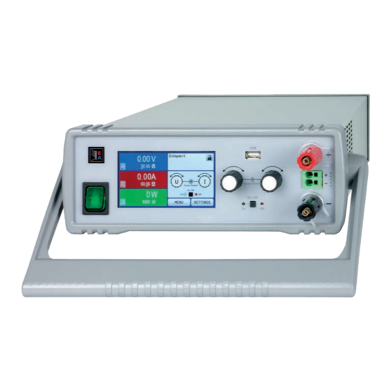
Dc laboratory power supply
Hide thumbs
Also See for PSI 9000 DT Series:
- Operating manual (80 pages) ,
- Operating manual (162 pages)
Table of Contents
Advertisement
Quick Links
Advertisement
Table of Contents


Need help?
Do you have a question about the PSI 9000 DT Series and is the answer not in the manual?
Questions and answers