Table of Contents
Advertisement
Quick Links
Download this manual
See also:
Operating Manual
Advertisement
Table of Contents

Related Manuals for Elektro-Automatik PSI 9000 DT


Summary of Contents for Elektro-Automatik PSI 9000 DT
-
Page 1: Operating Guide
Operating Guide PSI 9000 DT DC Laboratory Power Supply Doc ID: PSI9DTEN Revision: 03 Date: 11/2016... -
Page 3: Table Of Contents
PSI 9000 DT Series TABLE OF CONTENTS GENERAL OPERATION AND APPLICATION About this document ........5 Personal safety ..........40 1.1.1 Retention and use ..........5 Operating modes .........40 1.1.2 Copyright ............5 3.2.1 Voltage regulation / Constant voltage ..40 1.1.3 Validity ............5 3.2.2 Current regulation / constant current / current limiting ............41... - Page 4 PSI 9000 DT Series SERVICE AND MAINTENANCE Maintenance / cleaning ........74 4.2 Fault finding / diagnosis / repair....74 4.2.1 Replacing a defect mains fuse ....74 4.2.2 Firmware updates ........74 Calibration ............75 4.3.1 Preface ............75 4.3.2 Preparation ...........75 4.3.3 Calibration procedure ........75 CONTACT AND SUPPORT General ............77 Contact options ..........77...
-
Page 5: General
EA Elektro-Automatik guarantees the functional competence of the applied technology and the stated performance parameters. The warranty period begins with the delivery of free from defects equipment. Terms of guarantee are included in the general terms and conditions (TOS) of EA Elektro-Automatik. Limitation of liability All statements and instructions in this manual are based on current norms and regulations, up-to-date technology and our long term knowledge and experience. -
Page 6: Disposal Of Equipment
PSI 9000 DT Series Disposal of equipment A piece of equipment which is intended for disposal must, according to European laws and regulations (ElektroG, WEEE) be returned to the manufacturer for scrapping, unless the person operating the piece of equipment or an- other, delegated person is conducting the disposal. -
Page 7: Safety
PSI 9000 DT Series Safety 1.7.1 Safety notices Mortal danger - Hazardous voltage • Electrical equipment operation means that some parts can be under dangerous voltage. Therefore all parts under voltage must be covered! This basically applies to all models, though 40 V models according to SELV can not generate hazardous DC voltage. -
Page 8: Responsibility Of The Operator
PSI 9000 DT Series 1.7.3 Responsibility of the operator Operator is any natural or legal person who uses the equipment or delegates the usage to a third party, and is responsible during its usage for the safety of the user, other personnel or third parties. -
Page 9: Alarm Signals
PSI 9000 DT Series 1.7.5 Alarm signals The equipment offers various possibilities for signalling alarm conditions, however, not for danger situations. The signals may be optical (on the display as text) acoustic (piezo buzzer) or electronic (pin/status output of an analog interface). -
Page 10: Specific Technical Data
PSI 9000 DT Series 1.8.3 Specific technical data Model 320 W PSI 9040-20 DT PSI 9080-10 DT PSI 9200-04 DT AC Input Voltage range 90...264 V AC 90...264 V AC 90...264 V AC Connection 1ph,N,PE 1ph,N,PE 1ph,N,PE Frequency 45-65 Hz... - Page 11 PSI 9000 DT Series Model 320 W PSI 9040-20 DT PSI 9080-10 DT PSI 9200-04 DT Power regulation Display: Resolution See section „1.9.5.4. Resolution of the displayed values“ Display: Accuracy ≤ 0.8% P ≤ 0.8% P ≤ 0.8% P Efficiency ~ 92% ~ 92% ~ 93%...
- Page 12 PSI 9000 DT Series Model 640 W PSI 9040-40 DT PSI 9080-20 DT PSI 9200-10 DT AC Input Voltage range 90...264 V AC 90...264 V AC 90...264 V AC Connection 1ph,N,PE 1ph,N,PE 1ph,N,PE Frequency 45-65 Hz 45-65 Hz 45-65 Hz...
- Page 13 PSI 9000 DT Series Model 640 W PSI 9040-40 DT PSI 9080-20 DT PSI 9200-10 DT Power regulation Display: Resolution See section „1.9.5.4. Resolution of the displayed values“ Display: Accuracy ≤ 0.8% P ≤ 0.8% P ≤ 0.8% P Efficiency ~ 92% ~ 92% ~ 93%...
- Page 14 PSI 9000 DT Series Model 1000 W PSI 9040-40 DT PSI 9080-40 DT PSI 9200-15 DT AC Input Voltage range 90...264 V AC 90...264 V AC 90...264 V AC Connection 1ph,N,PE 1ph,N,PE 1ph,N,PE Frequency 45-65 Hz 45-65 Hz 45-65 Hz...
- Page 15 PSI 9000 DT Series Model 1000 W PSI 9040-40 DT PSI 9080-40 DT PSI 9200-15 DT Power regulation Display: Resolution See section „1.9.5.4. Resolution of the displayed values“ Display: Accuracy ≤ 0.8% P ≤ 0.8% P ≤ 0.8% P Efficiency ~ 92% ~ 92% ~ 92%...
- Page 16 PSI 9000 DT Series Model 1000 W PSI 9360-10 DT PSI 9500-06 DT PSI 9750-04 DT AC Input Voltage range 90...264 V AC 90...264 V AC 90...264 V AC Connection 1ph,N,PE 1ph,N,PE 1ph,N,PE Frequency 45-65 Hz 45-65 Hz 45-65 Hz...
- Page 17 PSI 9000 DT Series Model 1000 W PSI 9360-10 DT PSI 9500-06 DT PSI 9750-04 DT Power regulation Display: Resolution See section „1.9.5.4. Resolution of the displayed values“ Display: Accuracy ≤ 0.8% P ≤ 0.8% P ≤ 0.8% P Efficiency ~ 92% ~ 92% ~ 92%...
- Page 18 PSI 9000 DT Series Model 1500 W PSI 9040-60 DT PSI 9080-60 DT PSI 9200-25 DT AC Input Voltage range without derating 150...264 V AC 150...264 V AC 150...264 V AC Voltage range with derating 90...150 V AC 90...150 V AC 90...150 V AC...
- Page 19 PSI 9000 DT Series Model 1500 W PSI 9040-60 DT PSI 9080-60 DT PSI 9200-25 DT Power regulation Display: Resolution See section „1.9.5.4. Resolution of the displayed values“ Display: Accuracy ≤ 0.8% P ≤ 0.8% P ≤ 0.8% P Efficiency ~ 92% ~ 92% ~ 92%...
- Page 20 PSI 9000 DT Series Model 1500 W PSI 9360-15 DT PSI 9500-10 DT PSI 9750-06 DT AC Input Voltage range without derating 150...264 V AC 150...264 V AC 150...264 V AC Voltage range with derating 90...150 V AC 90...150 V AC 90...150 V AC...
- Page 21 PSI 9000 DT Series Model 1500 W PSI 9360-15 DT PSI 9500-10 DT PSI 9750-06 DT Power regulation Display: Resolution See section „1.9.5.4. Resolution of the displayed values“ Display: Accuracy ≤ 0.8% P ≤ 0.8% P ≤ 0.8% P Efficiency ~ 93% ~ 93% ~ 93%...
-
Page 22: Views
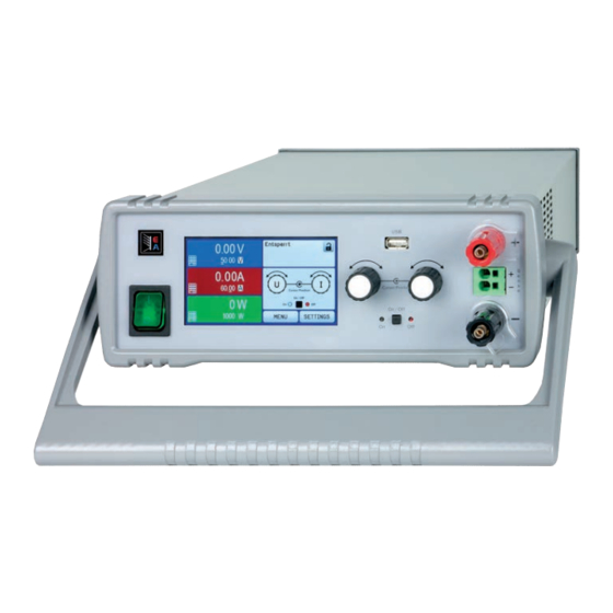
PSI 9000 DT Series 1.8.4 Views Figure 1 - Front (carrying handle vertical position) Figure 2 - Rear side (view of 1000 W / 1500 W models shown) A - Mains switch F - Control interfaces (digital, analog) B - Control panel... - Page 23 PSI 9000 DT Series Figure 3 - Side view (with air inlets) Figure 4 - View from above (320 W & 640 W models) EA Elektro-Automatik GmbH Fon: +49 2162 / 3785-0 www.elektroautomatik.de Page 23 Helmholtzstr. 31-33 • 41747 Viersen Fax: +49 2162 / 16230 ea1974@elektroautomatik.de...
- Page 24 PSI 9000 DT Series Figure 5 - View from above (1000 W & 1500 W models) EA Elektro-Automatik GmbH Fon: +49 2162 / 3785-0 www.elektroautomatik.de Page 24 Helmholtzstr. 31-33 • 41747 Viersen Fax: +49 2162 / 16230 ea1974@elektroautomatik.de Germany...
- Page 25 PSI 9000 DT Series Figure 6 - Control Panel Overview of the elements of the operating panel For a detailed description see section „1.9.5. The control panel (HMI)“. Touchscreen display Used for selection of set values, menus, conditions and display of actual values and status.
-
Page 26: Construction And Function
1.9.1 General description The DC laboratory power supplies of the PSI 9000 DT series are especially suitable for the use in test and devel- opment applications, in laboratories, research and industry. The robust enclosure with its carrying handle, which also serves as tilt stand, adapts in shape and look to measuring devices of established manufacturers. -
Page 27: Scope Of Delivery
The below liste optional accessories can be purchased separately from the device and can be installed by the user: 19" PSI/EL 9000 DT Metal frame kit for the mount of one PSI 9000 DT device in a 19" system (cabinet, rack). Height: 2U. -
Page 28: The Control Panel (Hmi)
PSI 9000 DT Series 1.9.5 The control panel (HMI) The HMI (Human Machine Interface) consists of a display with touchscreen, two rotary knobs, a pushbutton and a USB-A port. 1.9.5.1 Touchscreen display The graphic touchscreen display is divided into a number of areas. The complete display is touch sensitive and can be operated by finger or stylus to control the equipment. - Page 29 PSI 9000 DT Series • Status display (upper right) This area displays various status texts and symbols: Display Description Locked The HMI is locked Unlocked The HMI is unlocked Remote: The device is under remote control from..Analog ..the built-in analog interface ..the built-in USB port...
- Page 30 PSI 9000 DT Series 1.9.5.4 Resolution of the displayed values In the display, set values can be adjusted in fixed increments. The number of decimal places depends on the device model. The values have 3 to 5 digits. Actual and set values always have the same number of digits. Adjustable resolution and display formats for the touch panel display:...
-
Page 31: Usb Port (Rear Side)
USB stick and installs a virtual COM port. Details for remote control can be found on the web site of Elektro-Automatik or on the included USB stick. A general programming introduction for the USB port is available (date: 11-23-2016) The device can be addressed via this port either using the international standard ModBus protocol or by SCPI language. -
Page 32: Installation & Commissioning
Preparation Mains connection for a PSI 9000 DT series device is done via the included 2 meters long 3 pole mains cord. In case a different AC wiring is required, make sure that the other cable has at least a cross section of 2.5 mm² (AWG 12) is used. - Page 33 PSI 9000 DT Series 2.3.3.1 The handle The included handle is not only used to carry the device, it can also uplift the device’s front for easier access to knobs and buttons or better display readability. The handle can be rotated into various positions in an angle of 300°, such as a variable position (60...150°), 0°, -45°, -90°...
- Page 34 PSI 9000 DT Series Standing surface (handle in -45° position) 2.3.3.3 Installation in a 19” system The optionally available 2U mounting frame (see 1.9.4) can be used to install the power supply in a 19” cabinet or other 19” related system with at least 2U of space. The frame will center the device horizontally on the front plate of the frame.
- Page 35 PSI 9000 DT Series Figure 8 - Removal of the front and rear frame Figure 9 - Assembly steps for the mounting frame EA Elektro-Automatik GmbH Fon: +49 2162 / 3785-0 www.elektroautomatik.de Page 35 Helmholtzstr. 31-33 • 41747 Viersen Fax: +49 2162 / 16230 ea1974@elektroautomatik.de...
- Page 36 PSI 9000 DT Series Figure 10 - Positions for the hex spacers (3) (1000 W / 1500 W models shown) Figure 11 - Rear view after complete assembly of the mounting frame (1000 W / 1500 W models shown) Figure 12 - Front view after complete assembly of the mounting frame...
-
Page 37: Connection To Ac Supply
PSI 9000 DT Series 2.3.4 Connection to AC supply • The device can be connected to any wall socket or multi-socket outlet, as long as those feature a safety contact (PE) and are rated for 16 A. • When connecting the device to a multi-socket outlet, along with other electric devices, it is important to consider the total power consumption of all devices on the outlet, so that the maxi- mum current (power ÷ minimum voltage) does not exceed the definition for the wall socket,... -
Page 38: Grounding Of The Dc Output
PSI 9000 DT Series 2.3.6 Grounding of the DC output It is allowed to ground the DC output.The DC minus pole can be grounded right away, but it should only be done if absolutely necessary, because the DC output is coupled to PE via X capacitors in order to achieve a better HF filtering. -
Page 39: Connecting The Usb Port (Rear Side)
PSI 9000 DT Series 2.3.9 Connecting the USB port (rear side) In order to remotely control the device via this port, connect the device with a PC using the included USB cable and switch the device on. 2.3.9.1 Driver installation (Windows) On the initial connection with a PC the operating system will identify the device as new hardware and will start to install a driver. -
Page 40: Operation And Application
PSI 9000 DT Series Operation and application Personal safety • In order to guarantee safety when using the device, it is essential that only persons operate the device who are fully acquainted and trained in the required safety measures to be taken when working with dangerous electrical voltages • For models which can generate a voltage which is dangerous by contact, or is connected to... -
Page 41: Current Regulation / Constant Current / Current Limiting
PSI 9000 DT Series 3.2.2 Current regulation / constant current / current limiting Current regulation is also known as current limiting or constant current mode (CC). The DC output current is held constant by the power supply, once the output current to the load reaches the adjusted limit. Then the power supply automatically switches The current flowing from the power supply is determined by the... -
Page 42: Alarm Conditions
PSI 9000 DT Series Alarm conditions This section only gives an overview about device alarms. What to do in case your device indi- cates an alarm condition is described in section „3.6. Alarms and monitoring“. As a basic principle, all alarm conditions are signalled optically (text + message in the display), acoustically (if activated) and as a readable status and alarm counter via the digital interface. -
Page 43: Manual Operation
PSI 9000 DT Series Manual operation 3.4.1 Switching on the device The device should, as far as possible, always be switched on using the toggle switch on the front of the device. After switching on, the display will first show the company logo, followed by a language selection which will close automatically after 3 seconds and later manufacturer’s name and address, device type, firmware version(s), serial number and item number. - Page 44 PSI 9000 DT Series EA Elektro-Automatik GmbH Fon: +49 2162 / 3785-0 www.elektroautomatik.de Page 44 Helmholtzstr. 31-33 • 41747 Viersen Fax: +49 2162 / 16230 ea1974@elektroautomatik.de Germany...
- Page 45 PSI 9000 DT Series EA Elektro-Automatik GmbH Fon: +49 2162 / 3785-0 www.elektroautomatik.de Page 45 Helmholtzstr. 31-33 • 41747 Viersen Fax: +49 2162 / 16230 ea1974@elektroautomatik.de Germany...
- Page 46 PSI 9000 DT Series EA Elektro-Automatik GmbH Fon: +49 2162 / 3785-0 www.elektroautomatik.de Page 46 Helmholtzstr. 31-33 • 41747 Viersen Fax: +49 2162 / 16230 ea1974@elektroautomatik.de Germany...
- Page 47 PSI 9000 DT Series 3.4.3.1 Menu “General Settings” Setting P. Description Allow remote control Selection “NO” means that the device cannot be remotely controlled over either the digital or analog interfaces. If remote control is not allowed, the status will be shown as “local”...
- Page 48 PSI 9000 DT Series 3.4.3.2 Menu “User Events” See „3.6.2.1 User defined events“ on page 60. 3.4.3.3 Menu “Profiles” See „3.8 Loading and saving a user profile“ on page 62. 3.4.3.4 Menu “Overview” This menu page displays an overview of the set values (U, I, P or U, I, P, R) and alarm settings as well as settings limits.
- Page 49 PSI 9000 DT Series Submenu “Ethernet” Element Description Host name Configure the host name for the device here for the use with a local DNS entry Domain name Configure the domian name for the device here for the use with a local DNS entry TCP Keep-Alive Default setting: disabled Enables/disables the “keep-alive” functionality of TCP. Submenu “Com Protocols” (communication protocols) Element Description SCPI / ModBus Default setting: both enabled Enables/disables SCPI or ModBus communication protocols for the device. The change is immediately effective after submitting it with ENTER button.
-
Page 50: Adjustment Limits (Limits)
Changing the operating mode In general, the manual operation of a PSI 9000 DT distinguishes between two operating modes which are tied to set value input using the rotary knobs or ten-key pad. This assignment must be changed if one of the three set values is to be adjusted which is currently not available. -
Page 51: Manual Adjustment Of Set Values
PSI 9000 DT Series 3.4.6 Manual adjustment of set values The set values for voltage, current and power are the fundamental operating possibilities of a power supply and hence the two rotary knobs on the front of the device are always assigned to two of the the values in manual op- eration. -
Page 52: Switching The Main Screen View
PSI 9000 DT Series 3.4.7 Switching the main screen view The main screen, also called status page, with its set values, actual values and device status can be switched from the standard view mode with three or four values to a simpler mode with only voltage and current display. -
Page 53: Switching The Dc Output On Or Off
PSI 9000 DT Series 3.4.9 Switching the DC output on or off The DC output of the device can be manually or remotely switched on and off. This can be restricted in manual operation by the control panel being locked. -
Page 54: Remote Control
Programming details for the interfaces, the communication protocols etc. are to be found in the documentation “Programming Guide ModBus & SCPI“ which is supplied on the included USB stick or which is available as down- load from the EA Elektro-Automatik website. EA Elektro-Automatik GmbH Fon: +49 2162 / 3785-0 www.elektroautomatik.de... -
Page 55: Remote Control Via The Analog Interface (Ai)
PSI 9000 DT Series 3.5.4 Remote control via the analog interface (AI) 3.5.4.1 General The built-in, up to 1500 V DC galvanically isolated 15-pole analog interface (short: AI) is on the rear side of the device offers the following possibilities: • Remote control of current, voltage, power and internal resistance... - Page 56 PSI 9000 DT Series 3.5.4.3 Acknowledging device alarms Device alarms (see 3.6.2) are always indicated in the front display and some of them are also reported as signal on the analog interface socket (see 3.5.4.4), for example the overvoltage alarm (OV), which is considered as critical.
- Page 57 PSI 9000 DT Series 3.5.4.5 Overview of the Sub-D Socket 3.5.4.6 Simplified diagram of the pins Digital Input (DI) Analog Input (AI) V~0.5 It requires to use a switch with low resist- High resistance input (impedance ance (relay, switch, circuit breaker etc.) in >40 k...
- Page 58 PSI 9000 DT Series • Remote control is not active In this mode of operation pin “REM-SB” can serve as lock, preventing the DC output from being switched on by any means. This results in following possible situations: Parameter Behaviour output „REM-SB“...
-
Page 59: Alarms And Monitoring
PSI 9000 DT Series Alarms and monitoring 3.6.1 Definition of terms There is a clear distinction between device alarms (see „3.3. Alarm conditions“) such as overvoltage protection or overheating protection, and user defined events such as OVD (overvoltage detection). Whilst device alarms serve to protect the device and the connected load by initially switching off the DC output, user defined events can switch off the DC output (Action = ALARM), but can also simply give an acoustic signal to make the user aware. - Page 60 PSI 9000 DT Series These device alarms can’t be configured and are based on hardware: Alarm Meaning Description Indication AC supply over- or undervoltage. Triggers an alarm if the AC supply is out of specification or when the device is cut from supply, for example Display, analog & Power Fail when switching it off with the power switch. The DC output will be digital interface switched off.
-
Page 61: Control Panel (Hmi) Lock
PSI 9000 DT Series ► How to configure user defined events Tap the touch area on the main screen.. to select “4.1 Event U” or “4.2 Event I” or “4.3 On the right side tap the arrows Event P”. Set the monitoring limits with the left hand rotary knob and the triggered action with the right hand knob relevant to the application (also see „3.6.1. -
Page 62: Loading And Saving A User Profile
PSI 9000 DT Series Loading and saving a user profile The menu “Profiles” serves to select between a default profile and up to 5 user profiles. A profile is a collection of all settings and set values. Upon delivery, or after a reset, all 6 profiles have the same settings and all set values are 0. If the user changes settings or sets target values then these create a working profile which can be saved to one of the 5 user profiles. These profiles or the default one can then be switched. The default profile is read-only. The purpose of a profile is to load a set of set values, settings limits and monitoring thresholds quickly without having to readjust these. As all HMI settings are saved in the profile, including language, a profile change can also be accompanied by a change in HMI language. On calling up the menu page and selecting a profile the most important settings can be seen, but not changed. ► How to save the current values and settings as a user profile:... -
Page 63: The Function Generator
PSI 9000 DT Series The function generator 3.9.1 Introduction The built-in function generator (short: FG) is able to create various signal forms and apply them to the set value of voltage or current. All functions are based on a customisable arbitrary generator. In manual operation, the separate functions are available for selection and configuration on the front panel. In remote control, all functions are configured using... -
Page 64: Method Of Operation
PSI 9000 DT Series 3.9.2.3 Possible technical complications Operation of switching mode power supplies as a voltage source can, when applying a function to the output volt- age, lead to damage of the output capacitors due to continuous charging/discharging which causes overheating. -
Page 65: Sine Wave Function
PSI 9000 DT Series The static values are applied to the DC output immediately after loading the function, because it switches the DC output on automatically in order to settle the start situation. These static values represent start and end values for the progress of the function, so that the function does not need to start from 0. -
Page 66: Triangular Function
PSI 9000 DT Series 3.9.6 Triangular function The following parameters can be configured for a triangular wave function: Value Range Description I(A), U(A) 0...(Nominal value - (Off)) of U, I A = Amplitude of the signal to be generated I(Off), U(Off) 0...(Nominal value - (A)) of U, I Off = Offset, based on the foot of the triangular wave 0.1 ms...36000 s... -
Page 67: Trapezoidal Function
PSI 9000 DT Series 3.9.8 Trapezoidal function The following parameters can be configured for a trapezoidal curve function: Value Range Description I(A), U(A) 0...(Nominal value - (Off)) of U, I A = Amplitude of the signal to be generated I(Off), U(Off) 0...(Nominal value - (A)) of U, I Off = Offset, based on the foot of the trapezium 0.1 ms...36000 s... -
Page 68: Arbitrary Function
PSI 9000 DT Series 3.9.10 Arbitrary function The arbitrary (freely definable) function offers the user further scope. Up to 100 sequences are available for use for current I or voltage U, all of which have the same parameters but which can be differently configured so that a complex function process can be built up. The 100 sequences can run one after another in a sequence block, and this sequence block can then be repeated many times or endlessly. From the 100 sequences a block can be freely defined to run from sequence x to sequence y. A sequence or sequence block acts only on current or volt-... - Page 69 PSI 9000 DT Series Schematic diagram: Applications and results: Example 2 Focussing 1 cycle of 1 sequence from 100: The DC values at start and end are the same but the AC (amplitude) not. The end value is higher than the start so that the amplitude increases with each new half sine wave continuously through the sequence.
- Page 70 PSI 9000 DT Series By linking together a number of differently configured sequences, complex progressions can be created. Smart configuration of the arbitrary generator can be used to match triangular, sine, rectangular or trapezoidal wave func- tions and thus, e.g. a sequence of rectangular waves with differing amplitudes or duty cycles could be produced. Assignment to U or I makes 100 sequences available for the use on either current or voltage, but not on a mix of both.
- Page 71 PSI 9000 DT Series 3.9.10.1 Loading and saving the arbitrary function The 100 sequences of the arbitrary function, which can be manually configured with the control panel of the de- vice and which are applicable either to voltage (U) or current (I), can be saved to or loaded from a common USB stick via the front side USB port. Generally, all 100 sequences are saved or loaded using a text file of type CSV (semicolon separator), which represents a table of values.
-
Page 72: Ramp Function
PSI 9000 DT Series ► How to save a sequence table (100 sequences) to a USB stick: Do not plug the USB stick yet or remove it. Access the function selection menu of the function generator via MENU -> Function Generator -> Arbitrary... -
Page 73: Other Applications
PSI 9000 DT Series 3.10 Other applications 3.10.1 Series connection Series connection of two or multiple devices is basically possible, but for reasons of safety and isolation following restrictions apply: • Both, negative (DC-) and positive (DC+) output poles are coupled to PE via type X capacitors, limiting the max. -
Page 74: Service And Maintenance
PSI 9000 DT Series Service and maintenance Maintenance / cleaning The device needs no maintenance. Cleaning may be needed for the internal fans, the frequency of cleanse is depending on the ambient conditions. The fans serve to cool the components which are heated by the inherent power loss. Heavily dirt filled fans can lead to insufficient airflow and therefore the DC output would switch off too... -
Page 75: Calibration
4.3.1 Preface The devices of series PSI 9000 DT feature a function to readjust the most important output values when doing a calibration and in case these values have moved out of tolerance. The readjustment is limited to compensate small differences of up to 1% or 2% of the max. value. There are several reasons which could make it necessary to readjust a unit: component aging, component deterioration, extreme ambient conditions, high frequent use. - Page 76 PSI 9000 DT Series 4.3.3.1 Set values ► How to calibrate the voltage Connect a multimeter to the DC output. Connect a load and set its cur- rent to approx. 5% of the nominal current of the power supply, in this example ~3 A, and 0 V (if the load is electronic).
-
Page 77: Contact And Support
PSI 9000 DT Series 4.3.3.3 Save and exit After calibration you may furthermore enter the current date as “calibration date” by tapping in the selection screen and enter the date in format YYYY / MM / DD. Last but not least save the calibration data permanently by tapping Leaving the calibration selection menu without tapping “Save and exit”... - Page 80 EA-Elektro-Automatik GmbH & Co. KG Development - Production - Sales Helmholtzstraße 31-37 41747 Viersen Germany Fon: +49 2162 37 850 Fax: +49 02162 16 230 ea1974@elektroautomatik.de www.elektroautomatik.de...
Need help?
Do you have a question about the PSI 9000 DT and is the answer not in the manual?
Questions and answers