
Related Manuals for Elektro-Automatik PSI 9000 2U Series


Summary of Contents for Elektro-Automatik PSI 9000 2U Series
- Page 1 Betriebsanleitung PSI 9000 2U DC-Labornetzgerät Doc ID: PSI92UDE Revision: 02 Date: 04/2014...
-
Page 3: Table Of Contents
3.8.12 UI- und IU-Tabellenfunktion (XY-Tabelle) ..72 2.3.7 Anschluß der Fernfühlung ......37 3.8.13 PV-Tabellenfunktion (Photovoltaik) .....74 2.3.8 Installation eines AnyBus-Schnittstellenmo- 3.8.14 FC-Tabellenfunktion (Brennstoffzelle) ..75 duls ...............38 EA Elektro-Automatik GmbH Telefon: 02162 / 3785-0 www.elektroautomatik.de Seite 3 Helmholtzstr. 31-33 • 41747 Viersen Telefax: 02162 / 16230 ea1974@elektroautomatik.de... - Page 4 Einleitung ............86 4.4.2 Vorbereitung ..........86 4.4.3 Abgleichvorgang ..........86 ZUBEHÖR UND OPTIONEN Übersicht ............88 SERVICE & SUPPORT Übersicht ............88 Kontaktmöglichkeiten ........88 EA Elektro-Automatik GmbH Telefon: 02162 / 3785-0 www.elektroautomatik.de Seite 4 Helmholtzstr. 31-33 • 41747 Viersen Telefax: 02162 / 16230 ea1974@elektroautomatik.de...
-
Page 5: Allgemeines
• Verwendung nicht zugelassener Ersatzteile Der tatsächliche Lieferumfang kann bei Sonderausführungen, der Inanspruchnahme zusätzlicher Bestelloptionen oder aufgrund neuester technischer Änderungen von den hier beschriebenen Erläuterungen und Darstellungen abweichen. EA Elektro-Automatik GmbH Telefon: 02162 / 3785-0 www.elektroautomatik.de Seite 5 Helmholtzstr. 31-33 • 41747 Viersen Telefax: 02162 / 16230 ea1974@elektroautomatik.de... -
Page 6: Entsorgung Des Gerätes
Spannungs- und Stromquellen aller Art. • Ansprüche jeglicher Art wegen Schäden aus nicht bestimmungsgemäßer Verwendung sind ausgeschlossen • Für alle Schäden durch nicht bestimmungsgemäße Verwendung haftet allein der Betreiber EA Elektro-Automatik GmbH Telefon: 02162 / 3785-0 www.elektroautomatik.de Seite 6 Helmholtzstr. 31-33 • 41747 Viersen Telefax: 02162 / 16230 ea1974@elektroautomatik.de... -
Page 7: Sicherheit
• vor Arbeitsbeginn die Betriebsanleitung vollständig gelesen und verstanden haben. • die vorgeschriebenen und empfohlenen Schutzausrüstungen anwenden. Weiterhin ist jeder an dem Gerät Beschäftigte in seinem Zuständigkeitsumfang dafür verantwortlich, daß das Gerät stets in technisch einwandfreiem Zustand ist. EA Elektro-Automatik GmbH Telefon: 02162 / 3785-0 www.elektroautomatik.de Seite 7 Helmholtzstr. -
Page 8: Pflichten Des Betreibers
Nicht eingewiesene Personen kennen die Gefahren im Arbeitsbereich nicht und gelten als unbefugt. • Unbefugte Personen sind vom Arbeitsbereich fernhalten. Im Zweifel betreffende Personen ansprechen und aus dem Arbeitsbereich weisen. • Arbeiten unterbrechen, solange sich Unbefugte im Arbeitsbereich aufhalten. EA Elektro-Automatik GmbH Telefon: 02162 / 3785-0 www.elektroautomatik.de Seite 8 Helmholtzstr. -
Page 9: Alarmsignale
Allgemeine technische Daten Ausführung der Anzeige: Grafisches Touchscreen-Display 192 x 128 Punkte, resistiv Bedienelemente: 2 Drehknöpfe mit Tastfunktion, 1 Drucktaste Die Nennwerte des Gerätes bestimmen den maximal einstellbaren Bereich. EA Elektro-Automatik GmbH Telefon: 02162 / 3785-0 www.elektroautomatik.de Seite 9 Helmholtzstr. 31-33 • 41747 Viersen Telefax: 02162 / 16230... -
Page 10: Spezifische Technische Daten
(2 RMS-Wert: NF 0...300 kHz, PP-Wert: HF 0...20MHz (3 Typischer Wert bei 100% Ausgangsspannung und 100% Last (4 Die Genauigkeit der Anzeige addiert sich bei Istwerten zur allgemeinen Genauigkeit des Wertes am DC-Ausgang, bei Sollwerten subtrahiert sie sich EA Elektro-Automatik GmbH Telefon: 02162 / 3785-0 www.elektroautomatik.de Seite 10 Helmholtzstr. - Page 11 (2 Die Genauigkeit der Anzeige addiert sich bei Istwerten zur allgemeinen Genauigkeit des Wertes am DC-Ausgang, bei Sollwerten subtrahiert sie sich (3 Technische Daten der Analogschnittstelle siehe „3.4.4.3 Spezifikation der Analogschnittstelle“ auf Seite 57 EA Elektro-Automatik GmbH Telefon: 02162 / 3785-0 www.elektroautomatik.de...
- Page 12 (2 RMS-Wert: NF 0...300 kHz, PP-Wert: HF 0...20MHz (3 Typischer Wert bei 100% Ausgangsspannung und 100% Last (4 Die Genauigkeit der Anzeige addiert sich bei Istwerten zur allgemeinen Genauigkeit des Wertes am DC-Ausgang, bei Sollwerten subtrahiert sie sich EA Elektro-Automatik GmbH Telefon: 02162 / 3785-0 www.elektroautomatik.de Seite 12 Helmholtzstr.
- Page 13 (2 Die Genauigkeit der Anzeige addiert sich bei Istwerten zur allgemeinen Genauigkeit des Wertes am DC-Ausgang, bei Sollwerten subtrahiert sie sich (3 Technische Daten der Analogschnittstelle siehe „3.4.4.3 Spezifikation der Analogschnittstelle“ auf Seite 57 EA Elektro-Automatik GmbH Telefon: 02162 / 3785-0 www.elektroautomatik.de...
- Page 14 (2 RMS-Wert: NF 0...300 kHz, PP-Wert: HF 0...20MHz (3 Typischer Wert bei 100% Ausgangsspannung und 100% Last (4 Die Genauigkeit der Anzeige addiert sich bei Istwerten zur allgemeinen Genauigkeit des Wertes am DC-Ausgang, bei Sollwerten subtrahiert sie sich EA Elektro-Automatik GmbH Telefon: 02162 / 3785-0 www.elektroautomatik.de Seite 14 Helmholtzstr.
- Page 15 (2 Die Genauigkeit der Anzeige addiert sich bei Istwerten zur allgemeinen Genauigkeit des Wertes am DC-Ausgang, bei Sollwerten subtrahiert sie sich (2 Technische Daten der Analogschnittstelle siehe „3.4.4.3 Spezifikation der Analogschnittstelle“ auf Seite 57 EA Elektro-Automatik GmbH Telefon: 02162 / 3785-0 www.elektroautomatik.de...
- Page 16 (2 RMS-Wert: NF 0...300 kHz, PP-Wert: HF 0...20MHz (3 Typischer Wert bei 100% Ausgangsspannung und 100% Last (4 Die Genauigkeit der Anzeige addiert sich bei Istwerten zur allgemeinen Genauigkeit des Wertes am DC-Ausgang, bei Sollwerten subtrahiert sie sich EA Elektro-Automatik GmbH Telefon: 02162 / 3785-0 www.elektroautomatik.de Seite 16 Helmholtzstr.
- Page 17 (2 Die Genauigkeit der Anzeige addiert sich bei Istwerten zur allgemeinen Genauigkeit des Wertes am DC-Ausgang, bei Sollwerten subtrahiert sie sich (2 Technische Daten der Analogschnittstelle siehe „3.4.4.3 Spezifikation der Analogschnittstelle“ auf Seite 57 EA Elektro-Automatik GmbH Telefon: 02162 / 3785-0 www.elektroautomatik.de...
- Page 18 (2 RMS-Wert: NF 0...300 kHz, PP-Wert: HF 0...20MHz (3 Typischer Wert bei 100% Ausgangsspannung und 100% Last (4 Die Genauigkeit der Anzeige addiert sich bei Istwerten zur allgemeinen Genauigkeit des Wertes am DC-Ausgang, bei Sollwerten subtrahiert sie sich EA Elektro-Automatik GmbH Telefon: 02162 / 3785-0 www.elektroautomatik.de Seite 18 Helmholtzstr.
- Page 19 (2 Die Genauigkeit der Anzeige addiert sich bei Istwerten zur allgemeinen Genauigkeit des Wertes am DC-Ausgang, bei Sollwerten subtrahiert sie sich (2 Technische Daten der Analogschnittstelle siehe „3.4.4.3 Spezifikation der Analogschnittstelle“ auf Seite 57 EA Elektro-Automatik GmbH Telefon: 02162 / 3785-0 www.elektroautomatik.de...
- Page 20 (2 RMS-Wert: NF 0...300 kHz, PP-Wert: HF 0...20MHz (3 Typischer Wert bei 100% Ausgangsspannung und 100% Last (4 Die Genauigkeit der Anzeige addiert sich bei Istwerten zur allgemeinen Genauigkeit des Wertes am DC-Ausgang, bei Sollwerten subtrahiert sie sich EA Elektro-Automatik GmbH Telefon: 02162 / 3785-0 www.elektroautomatik.de Seite 20 Helmholtzstr.
- Page 21 (2 Die Genauigkeit der Anzeige addiert sich bei Istwerten zur allgemeinen Genauigkeit des Wertes am DC-Ausgang, bei Sollwerten subtrahiert sie sich (2 Technische Daten der Analogschnittstelle siehe „3.4.4.3 Spezifikation der Analogschnittstelle“ auf Seite 57 EA Elektro-Automatik GmbH Telefon: 02162 / 3785-0 www.elektroautomatik.de...
-
Page 22: Ansichten
PSI 9000 2U Serie 1.9.4 Ansichten Bild 1 - Vorderseite Bild 2 - Rückseite EA Elektro-Automatik GmbH Telefon: 02162 / 3785-0 www.elektroautomatik.de Seite 22 Helmholtzstr. 31-33 • 41747 Viersen Telefax: 02162 / 16230 ea1974@elektroautomatik.de... - Page 23 PSI 9000 2U Serie EA Elektro-Automatik GmbH Telefon: 02162 / 3785-0 www.elektroautomatik.de Seite 23 Helmholtzstr. 31-33 • 41747 Viersen Telefax: 02162 / 16230 ea1974@elektroautomatik.de...
- Page 24 PSI 9000 2U Serie Bild 5 - Ansicht von oben, mit DC-Abdeckung (Klemme Typ 1) EA Elektro-Automatik GmbH Telefon: 02162 / 3785-0 www.elektroautomatik.de Seite 24 Helmholtzstr. 31-33 • 41747 Viersen Telefax: 02162 / 16230 ea1974@elektroautomatik.de...
- Page 25 Gerät erkannt zu werden. Mit dem USB-Stick können Wertetabellen für den Funk- tionsgenerator (UI- und IU-Funktion) geladen bzw. die 100 Sequenzen der Arbiträr-Funktion geladen oder gespeichert werden. EA Elektro-Automatik GmbH Telefon: 02162 / 3785-0 www.elektroautomatik.de Seite 25 Helmholtzstr.
-
Page 26: Aufbau Und Funktion
Elemente (KE, DR, BE), die von Firmwareaktualisierungen betroffen sein können. Share & Sense Power block Controller 1...3 (DR) Commu- HMI (BE) nication (KE) PSI 9000 2U/3U Block diagram EA Elektro-Automatik GmbH Telefon: 02162 / 3785-0 www.elektroautomatik.de Seite 26 Helmholtzstr. 31-33 • 41747 Viersen Telefax: 02162 / 16230 ea1974@elektroautomatik.de... -
Page 27: Lieferumfang
Für weitere Informationen siehe Produktkatalog oder auf Anfrage. Höhere Dynamik der Ausgangsspannung durch reduzierte Ausgangskapazität. „High-Speed Ramping“ Es gilt zu beachten, daß sich andere Ausgangswerte, wie die Restwelligkeit, auch erhöhen! Dies ist eine dauerhafte Modifikation, die nicht abschaltbar ist. EA Elektro-Automatik GmbH Telefon: 02162 / 3785-0 www.elektroautomatik.de Seite 27 Helmholtzstr. 31-33 • 41747 Viersen Telefax: 02162 / 16230 ea1974@elektroautomatik.de... -
Page 28: Die Bedieneinheit (Hmi)
Ω 0-100% R Einstellwert für den gewünschten Reihen-Innenwiderstand Gilt auch für weitere, auf diese phys. Einheit bezogene Werte, wie z. B. OVD zur Spannung oder UCD zum Strom EA Elektro-Automatik GmbH Telefon: 02162 / 3785-0 www.elektroautomatik.de Seite 28 Helmholtzstr. 31-33 • 41747 Viersen Telefax: 02162 / 16230 ea1974@elektroautomatik.de... - Page 29 Die Drehknöpfe selbst haben auch eine Tastfunktion, die in allen Einstellmenüs, wo Werte gestellt werden können, zum Verschieben des Cursors von niederwertigen zu höherwertigen Dezimalpositionen (rotierend) des einzustellenden Wertes dienen: EA Elektro-Automatik GmbH Telefon: 02162 / 3785-0 www.elektroautomatik.de Seite 29 Helmholtzstr.
- Page 30 BE1_V202.bin. Andere werden nicht erkannt und nicht aufgelistet. wave_u<beliebig>.csv Funktionsgenerator-Arbiträr-Kurve für die Spannung U bzw. Strom I. wave_i<beliebig>.csv Der Name muß am Anfang wave_u oder wave_i enthalten, der Rest ist beliebig. EA Elektro-Automatik GmbH Telefon: 02162 / 3785-0 www.elektroautomatik.de Seite 30 Helmholtzstr. 31-33 • 41747 Viersen Telefax: 02162 / 16230 ea1974@elektroautomatik.de...
-
Page 31: Usb-Port (Rückseite)
Das bestückte Modul hat, wenn Fernsteuerung aktiviert werden soll, keinen Vorrang vor der USB-Schnittstelle oder der Analogschnittstelle und kann daher nur abwechselnd zu diesen benutzt werden. Jedoch ist Überwachung (Monitoring) immer möglich. Stecken bzw. Abziehen des Moduls nur bei ausgeschaltetem Gerät! EA Elektro-Automatik GmbH Telefon: 02162 / 3785-0 www.elektroautomatik.de Seite 31 Helmholtzstr. -
Page 32: Analogschnittstelle
Master-Slave-System verbinden kann. Die Verbindung erfolgt mit handelsüblichen CAT5-Kabeln. Durch den verwendeten Standard RS485 sind theoretisch Kabellängen bis 1200 m verwendbar. Es wird jedoch empfohlen, immer möglichst kurze Kabel zu verwenden. EA Elektro-Automatik GmbH Telefon: 02162 / 3785-0 www.elektroautomatik.de Seite 32 Helmholtzstr. -
Page 33: Installation & Inbetriebnahme
• Stellen Sie vor dem Anschluß des Gerätes an die AC-Stromzufuhr sicher, daß die auf dem Typenschild des Gerätes angegebenen Anschlußdaten eingehalten werden. Eine Überspan- nung am AC-Anschluß kann das Gerät beschädigen. EA Elektro-Automatik GmbH Telefon: 02162 / 3785-0 www.elektroautomatik.de Seite 33 Helmholtzstr. -
Page 34: Vorbereitung
Bei den Geräten der Serie PSI 9000 2U werden für die Umrüstung auf Tischgerät sogenannte Abdeckbleche mit- geliefert, die statt der Haltewinkel seitlich hinter die Frontplatte geklemmt werden, bevor die Griffe wieder montiert werden. Zulässige und unzulässige Aufstellpositionen: Aufstellfläche EA Elektro-Automatik GmbH Telefon: 02162 / 3785-0 www.elektroautomatik.de Seite 34 Helmholtzstr. 31-33 • 41747 Viersen Telefax: 02162 / 16230 ea1974@elektroautomatik.de... -
Page 35: Anschluß An Das Stromnetz (Ac)
Typ 2: Modelle ab 200 V Ausgangsspannung Schraubverbindung M8 an Messingblock Schraubverbindung M6 an Kupferschiene Empfehlung: Ringkabelschuhe mit 8er Loch Empfehlung: Ringkabelschuhe mit 6er Loch EA Elektro-Automatik GmbH Telefon: 02162 / 3785-0 www.elektroautomatik.de Seite 35 Helmholtzstr. 31-33 • 41747 Viersen Telefax: 02162 / 16230 ea1974@elektroautomatik.de... -
Page 36: Erdung Des Dc-Ausgangs
Trennung aufhebt • Bei Erdung einer der Ausgangspole muß beachtet werden, ob an der Last (z. B. elektronische Last) auch ein Eingangspol geerdet ist. Dies kann zu einem Kurzschluß führen! EA Elektro-Automatik GmbH Telefon: 02162 / 3785-0 www.elektroautomatik.de Seite 36 Helmholtzstr. -
Page 37: Anschluß Der Fernfühlung
• (+) Sense darf nur am (+) der Last und (–) Sense nur am (–) der Last angeschlossen werden. Ansonsten können beide Systeme beschädigt werden. • Bei Master-Slave-Betrieb sollte die Fernfühlung nur am Master-Gerät erfolgen Bild 7 - Beispiel Fernfühlungsverdrahtung EA Elektro-Automatik GmbH Telefon: 02162 / 3785-0 www.elektroautomatik.de Seite 37 Helmholtzstr. -
Page 38: Installation Eines Anybus-Schnittstellenmoduls
Die analoge Schnittstelle ist intern zum Gerät hin galvanisch getrennt. Verbinden Sie daher möglichst niemals eine Masse der analogen Schnittstelle (AGND) direkt oder indirekt (Erdung) mit dem DC-Minus-Ausgang, weil das die galvanische Trennung auf- hebt. EA Elektro-Automatik GmbH Telefon: 02162 / 3785-0 www.elektroautomatik.de Seite 38 Helmholtzstr. -
Page 39: Anschließen Des „Share-Bus
Falls der oben beschriebene CDC-Treiber auf Ihrem System nicht vorhanden ist oder aus irgendeinem Grund nicht richtig funktionieren sollte, können kommerzielle Anbieter Abhilfe schaffen. Suchen und finden Sie dazu im Internet diverse Anbieter mit den Schlüsselwörtern „cdc driver windows“ oder „cdc driver linux“ oder „cdc driver macos“. EA Elektro-Automatik GmbH Telefon: 02162 / 3785-0 www.elektroautomatik.de Seite 39 Helmholtzstr. -
Page 40: Erstinbetriebnahme
Erstinbetriebnahme. Siehe daher auch „2.3.12. Erstinbetriebnahme“. Erst nach erfolgreicher Überprüfung des Gerätes nach den gelisteten Punkten darf es wie gewohnt in Betrieb genommen werden. EA Elektro-Automatik GmbH Telefon: 02162 / 3785-0 www.elektroautomatik.de Seite 40 Helmholtzstr. -
Page 41: Bedienung Und Verwendung
P = U * I ein. Solange der DC-Ausgang eingeschaltet und Konstantstrombetrieb aktiv ist, wird der Zustand „CC-Betrieb aktiv“ als Kürzel CC auf der grafischen Anzeige und auch als Signal auf der analogen Schnittstelle ausgegeben, kann aber auch als Status über die digitalen Schnittstellen ausgelesen werden. EA Elektro-Automatik GmbH Telefon: 02162 / 3785-0 www.elektroautomatik.de Seite 41 Helmholtzstr. -
Page 42: Leistungsregelung / Konstantleistung / Leistungsbegrenzung
Regler im Gerät. Verdeutlichung: Soll Soll Soll Soll Bei aktivierter Innenwiderstandseinstellung, d.h. R-Modus, ist der Funktionsgenerator deaktiviert. EA Elektro-Automatik GmbH Telefon: 02162 / 3785-0 www.elektroautomatik.de Seite 42 Helmholtzstr. 31-33 • 41747 Viersen Telefax: 02162 / 16230... -
Page 43: Alarmzustände
• das Produkt aus der am DC-Ausgang anliegenden Ausgangsspannung und dem Ausgangsstrom die eingestellte OPP-Schwelle überschreitet Diese Schutzfunktion dient nicht dem Schutz des Gerätes, sondern dem Schutz der angeschlossenen Last, falls diese durch zu hohe Leistungsaufnahme beschädigt werden könnte. EA Elektro-Automatik GmbH Telefon: 02162 / 3785-0 www.elektroautomatik.de Seite 43 Helmholtzstr. -
Page 44: Manuelle Bedienung
Die Menüstruktur ist auf den folgenden Seiten als Schema darge- stellt. Einige Einstellparameter sind selbsterklärend, andere nicht. Diese werden auf den nachfolgenden Seite im Einzelnen erläutert. EA Elektro-Automatik GmbH Telefon: 02162 / 3785-0 www.elektroautomatik.de Seite 44 Helmholtzstr. 31-33 • 41747 Viersen Telefax: 02162 / 16230 ea1974@elektroautomatik.de... - Page 45 PSI 9000 2U Serie EA Elektro-Automatik GmbH Telefon: 02162 / 3785-0 www.elektroautomatik.de Seite 45 Helmholtzstr. 31-33 • 41747 Viersen Telefax: 02162 / 16230 ea1974@elektroautomatik.de...
- Page 46 PSI 9000 2U Serie EA Elektro-Automatik GmbH Telefon: 02162 / 3785-0 www.elektroautomatik.de Seite 46 Helmholtzstr. 31-33 • 41747 Viersen Telefax: 02162 / 16230 ea1974@elektroautomatik.de...
- Page 47 PSI 9000 2U Serie EA Elektro-Automatik GmbH Telefon: 02162 / 3785-0 www.elektroautomatik.de Seite 47 Helmholtzstr. 31-33 • 41747 Viersen Telefax: 02162 / 16230 ea1974@elektroautomatik.de...
- Page 48 Diese Menüseiten zeigen eine Übersicht der aktuellen Sollwerte (U, I, P bzw. U, I, P, R) und Gerätealarmein- stellungen, sowie die Eventeinstellungen und Einstellgrenzen an. Diese können hier nur angesehen und nicht verändert werden. EA Elektro-Automatik GmbH Telefon: 02162 / 3785-0 www.elektroautomatik.de Seite 48 Helmholtzstr.
- Page 49 (Location tag). Max. Länge: 22 Zeichen Datum der Installation Texteingabefeld zur Eingabe eines beliebigen Textes zum Profibus-Tag „Installa- tiondatum“ (Installation date). Max. Länge: 40 Zeichen Beschreib. Texteingabefeld zur Eingabe eines beliebigen Textes zur Beschreibung des Profibus- Slaves. Max. Länge: 54 Zeichen EA Elektro-Automatik GmbH Telefon: 02162 / 3785-0 www.elektroautomatik.de Seite 49 Helmholtzstr. 31-33 • 41747 Viersen Telefax: 02162 / 16230...
- Page 50 Beschreibung Dieses Modul bietet keine einstellbaren Werte. Die seriellen Einstellungen sind wie folgt festgelegt: Baudrate = 115200 Baud, 8 Datenbits, 1 Stopbit, Parität = keine EA Elektro-Automatik GmbH Telefon: 02162 / 3785-0 www.elektroautomatik.de Seite 50 Helmholtzstr. 31-33 • 41747 Viersen Telefax: 02162 / 16230 ea1974@elektroautomatik.de...
-
Page 51: Einstellgrenzen (Limits)
Die Einstellwerte können auch direkt über eine Zehnertastatur eingegeben werden. Diese er- scheint, wenn man auf der jeweiligen Seite, also z. B. „3. Limits“, auf das Bedienfeld mit der Drehknopfzuweisung (unten, Mitte) tippt. EA Elektro-Automatik GmbH Telefon: 02162 / 3785-0 www.elektroautomatik.de Seite 51 Helmholtzstr. -
Page 52: Betriebsart Wechseln
Die Einstellung des Innenwiderstandes R ist ein Sonderfall. Dieser ist nicht in der Hauptanzeige verfügbar, auch nicht wenn R-Modus aktiviert wurde. Er kann nur bei DC-Ausgang = aus und nur in SETTINGS eingestellt werden. EA Elektro-Automatik GmbH Telefon: 02162 / 3785-0 www.elektroautomatik.de Seite 52 Helmholtzstr. - Page 53 Stellen Sie den Wert wie gewünscht ein und übernehmen Sie den Werte mit ENTER oder verwerfen Sie den Wert mit ESC. Verlassen Sie SETTINGS und schalten Sie den DC-Ausgang wieder ein, damit der Widerstandswert aktiv werden kann. EA Elektro-Automatik GmbH Telefon: 02162 / 3785-0 www.elektroautomatik.de Seite 53 Helmholtzstr.
-
Page 54: Dc-Ausgang Ein- Oder Ausschalten
„Lokal“ wieder beendet, sprich die Fernsteuerung wieder erlaubt wird, weil der Pin „Remote“ an der Analogschnittstelle weiterhin das Signal „Fernsteuerung = ein“ vorgibt. Ausnahme: der Pegel des Pins „Remote“ wird während der Phase „Lokal“ auf HIGH geändert, also auf „Fernsteuerung = aus“. EA Elektro-Automatik GmbH Telefon: 02162 / 3785-0 www.elektroautomatik.de Seite 54 Helmholtzstr. -
Page 55: Fernsteuerung Über Eine Digitale Schnittstelle
3.4.3.3 Programmierung Details zur Programmierung der Schnittstellen, die Kommunikationsprotokolle usw. sind in der externen Dokumen- tation „Programmieranleitung ModBus & SCPI“ zu finden, die mit dem Gerät auf einer CD mitgeliefert wird bzw. als Download auf der Webseite des Geräteherstellers verfügbar ist. EA Elektro-Automatik GmbH Telefon: 02162 / 3785-0 www.elektroautomatik.de Seite 55 Helmholtzstr. 31-33 • 41747 Viersen Telefax: 02162 / 16230 ea1974@elektroautomatik.de... -
Page 56: Fernsteuerung Über Analogschnittstelle (As)
Leistung (PSEL) können fest auf 100% gelegt werden (Brücke nach VREF oder anders) Die Analogschnittstelle ist zum DC-Ausgang hin galvanisch getrennt. Daher: Niemals eine der Massen der Analogschnittstelle mit DC- oder DC+ Ausgang verbinden! 3.4.4.2 Übersicht Sub-D-Buchse EA Elektro-Automatik GmbH Telefon: 02162 / 3785-0 www.elektroautomatik.de Seite 56 Helmholtzstr. 31-33 • 41747 Viersen Telefax: 02162 / 16230 ea1974@elektroautomatik.de... - Page 57 Tabelle oben. LOW und kann keine Lasten treiben, AGND sondern nur schalten, wie im Bild links am Beispiel eines Relais‘ gezeigt. EA Elektro-Automatik GmbH Telefon: 02162 / 3785-0 www.elektroautomatik.de Seite 57 Helmholtzstr. 31-33 • 41747 Viersen Telefax: 02162 / 16230...
- Page 58 Die Alarme OT, OV, PF, OCP und OPP gelten als zu quittierende Fehler (siehe auch „3.5.2. Gerätealarme und Events handhaben“). Sie können durch Aus- und Wiedereinschalten des DC-Ausgangs per Pin REM-SB quittiert werden, also eine HIGH-LOW-HIGH-Flanke (mind. 50ms für LOW). EA Elektro-Automatik GmbH Telefon: 02162 / 3785-0 www.elektroautomatik.de Seite 58 Helmholtzstr.
-
Page 59: Alarme Und Überwachung
Ausgangsleistung am DC-Ausgang die eingestellte 0 W...1,1*P Digitale Schnitt- Nenn Protection Schwelle überschreitet. Außerdem wird der DC- stellen Ausgang ausgeschaltet. EA Elektro-Automatik GmbH Telefon: 02162 / 3785-0 www.elektroautomatik.de Seite 59 Helmholtzstr. 31-33 • 41747 Viersen Telefax: 02162 / 16230 ea1974@elektroautomatik.de... - Page 60 Diese Ereignisse sind nicht zu verwechseln mit Alarmen wie OT und OVP, die zum Schutz des Gerätes dienen. Events können, wenn auf Aktion ALARM gestellt, aber auch den DC-Ausgang ausschalten und somit die Last schützen. EA Elektro-Automatik GmbH Telefon: 02162 / 3785-0 www.elektroautomatik.de Seite 60 Helmholtzstr.
-
Page 61: Bedieneinheit (Hmi) Sperren
Es erscheint eine Abfrage Entsperren Sie das HMI mittels des Bedienfeldes „Entsperren“. Erfolgt innerhalb von 5 Sekunden keine Eingabe, wird die Abfrage wieder ausgeblendet und das HMI bleibt weiterhin gesperrt. EA Elektro-Automatik GmbH Telefon: 02162 / 3785-0 www.elektroautomatik.de Seite 61 Helmholtzstr. -
Page 62: Nutzerprofile Laden Und Speichern
In der nun erscheinenden Auswahl (siehe rechts) wählen Sie zwischen Nutzerprofil 1-5 aus, in welches Sie speichern wollen. Das gewählte Nutzerprofil wird daraufhin angezeigt. Sie können hier die Einstellungen und Werte noch einmal kontrollieren, jedoch nicht verändern. Speichern Sie mit Bedienfeld EA Elektro-Automatik GmbH Telefon: 02162 / 3785-0 www.elektroautomatik.de Seite 62 Helmholtzstr. 31-33 • 41747 Viersen Telefax: 02162 / 16230... -
Page 63: Der Funktionsgenerator
Dauerbetrieb durch Erhitzung die Beschädigung des Gerätes zur Folge haben kann. Weiterhin kann es auftreten, daß der tatsächliche Verlauf der Spannung, bei Anwendung einer Funktion auf U, anders als erwartet aussieht. EA Elektro-Automatik GmbH Telefon: 02162 / 3785-0 www.elektroautomatik.de Seite 63 Helmholtzstr. -
Page 64: Arbeitsweise
Funktion darstellen. Wenn Sie z. B. eine Funktion auf den Strom anwenden, dann sollte der Grenzwert für den Strom natürlich größer oder gleich Offset + Amplitude sein, um den Sollwertverlauf nicht zu beschneiden. Die Einstellungen der einzelnen Funktionen sind weiter unten beschrieben. EA Elektro-Automatik GmbH Telefon: 02162 / 3785-0 www.elektroautomatik.de Seite 64 Helmholtzstr. -
Page 65: Sinus-Funktion
60 V und sin(I) die Amplitude auf 12 A ein, bei einem Offset von 15 A. Die sich ergebende max. Leistung bei Erreichen des höchsten Punktes der Sinuskurve wäre dann (15 A + 12 A) * 60 V = 1620 W. EA Elektro-Automatik GmbH Telefon: 02162 / 3785-0 www.elektroautomatik.de Seite 65 Helmholtzstr. -
Page 66: Dreieck-Funktion
T = 1/f = 1/25 Hz = 40 ms berechnet werden. Für den Puls ergäben sich dann bei 80% Duty cycle t1 = 40 ms*0,8 = 32 ms. Die Zeit t2 wäre dann mit 8 ms zu setzen. EA Elektro-Automatik GmbH Telefon: 02162 / 3785-0 www.elektroautomatik.de Seite 66 Helmholtzstr. -
Page 67: Trapez-Funktion
Einstellung können auch andere Prüf- impulse nachgebildet werden. Soll die Kurve in Sequenz 4 einen Sinus enthalten, so müßte sie alternativ mit dem Arbiträrgenerator erzeugt werden. Sequenzen EA Elektro-Automatik GmbH Telefon: 02162 / 3785-0 www.elektroautomatik.de Seite 67 Helmholtzstr. 31-33 • 41747 Viersen Telefax: 02162 / 16230 ea1974@elektroautomatik.de... -
Page 68: Arbiträr-Funktion
1 s und die Frequenz 1 Hz, entstünde genau 1 Sinuswelle. Wäre bei gleicher Frequenz die Sequenzzeit nur 0,5 s, entstünde nur eine Sinushalbwelle. Seq.Zeit EA Elektro-Automatik GmbH Telefon: 02162 / 3785-0 www.elektroautomatik.de Seite 68 Helmholtzstr. 31-33 • 41747 Viersen Telefax: 02162 / 16230 ea1974@elektroautomatik.de... - Page 69 Einstellung der DC-Werte. Diese sind hier bei Start und Ende ungleich. Erzeugt wird eine Rampe mit anstei- gendem Verlauf. Seq.Zeit EA Elektro-Automatik GmbH Telefon: 02162 / 3785-0 www.elektroautomatik.de Seite 69 Helmholtzstr. 31-33 • 41747 Viersen Telefax: 02162 / 16230 ea1974@elektroautomatik.de...
- Page 70 Sequenz 3: Horizontale Rampe (f = 0) Sequenz 4: Abfallende Rampe (f = 0) Sequenz 1 Sequenz 2 Seq. 3 Sequenz 4 EA Elektro-Automatik GmbH Telefon: 02162 / 3785-0 www.elektroautomatik.de Seite 70 Helmholtzstr. 31-33 • 41747 Viersen Telefax: 02162 / 16230...
- Page 71 Tippen Sie unten rechts auf . Die gewählte Datei wird nun überprüft und, sofern in Ordnung, geladen. Bei Formatfehlern wird eine entsprechende Meldung angezeigt. Dann muß die Datei korrigiert und der Vorgang wiederholt werden. EA Elektro-Automatik GmbH Telefon: 02162 / 3785-0 www.elektroautomatik.de Seite 71 Helmholtzstr.
-
Page 72: Rampen-Funktion
Spannungswerte interpretiert, selbst wenn sie vom Anwender als Stromwerte berechnet und dann fälschlicherweise als UI-Tabelle geladen wurden. Diese Funktion eignet sich am besten zur Simulation von Brennstoffzellen. EA Elektro-Automatik GmbH Telefon: 02162 / 3785-0 www.elektroautomatik.de Seite 72 Helmholtzstr. - Page 73 Laden Sie die Funktion mit , um Sie dann zu starten und zu bedienen wie gewohnt (siehe auch „3.8.4.1. Auswahl und Steuerung einer Funktion“). EA Elektro-Automatik GmbH Telefon: 02162 / 3785-0 www.elektroautomatik.de Seite 73 Helmholtzstr. 31-33 • 41747 Viersen Telefax: 02162 / 16230 ea1974@elektroautomatik.de...
-
Page 74: Pv-Tabellenfunktion (Photovoltaik)
Lichtsituation des Solarpanels zwischen totaler Dunkelheit (0%) und minimaler Lichtfülle (100%) darstellt, die das Solarpanel benötigt Umpp um die max. Leistung zu liefern. EA Elektro-Automatik GmbH Telefon: 02162 / 3785-0 www.elektroautomatik.de Seite 74 Helmholtzstr. 31-33 • 41747 Viersen Telefax: 02162 / 16230 ea1974@elektroautomatik.de... -
Page 75: Fc-Tabellenfunktion (Brennstoffzelle)
Das bedeutet, von Punkt 1 bis Punkt 4 muß die Spannung abnehmen und der Strom ansteigen. Sollten die genannten Regeln nicht eingehalten werden, erscheint eine Fehlermeldung und die eingegebenen Werte werden auf 0 zurückgesetzt. EA Elektro-Automatik GmbH Telefon: 02162 / 3785-0 www.elektroautomatik.de Seite 75 Helmholtzstr. - Page 76 Die Ausgangsspannung stellt sich in Abhängigkeit vom Ausgangsstrom ein, der durch die angelegte variable Last definiert wird und nimmt mit steigendem Strom ab. Ohne Last geht die Spannung auf den Wert Uoc. Stoppen Sie jederzeit wie in 3.8.4.1 beschrieben. EA Elektro-Automatik GmbH Telefon: 02162 / 3785-0 www.elektroautomatik.de Seite 76 Helmholtzstr. 31-33 • 41747 Viersen Telefax: 02162 / 16230 ea1974@elektroautomatik.de...
-
Page 77: Fernsteuerung Des Funktionsgenerators
• Der Funktionsgenerator ist nicht verfügbar, wenn Geräte im Widerstands-Betrieb (R-Modus) arbeiten • Einige Funktionen basieren auf dem Arbiträrgenerator, andere auf dem XY-Generator. Daher sind beide getrennt zu bedienen • PV-Funktion und FC-Funktion (Fuel Cell) sind nicht fernsteuerbar EA Elektro-Automatik GmbH Telefon: 02162 / 3785-0 www.elektroautomatik.de Seite 77 Helmholtzstr. -
Page 78: Weitere Anwendungen
Gerätes enthalten) untereinander verbinden. Dabei ist es egal, welche der beiden Master-Slave- Anschlußbuchsen (RJ45, Rückseite) zum jeweils nächsten Gerät verbunden werden. Je nach gewünschter Konfiguration nun auch die Geräte DC-seitig verbinden. Folgende Konfigurationen bei Parallelschaltung sind möglich: EA Elektro-Automatik GmbH Telefon: 02162 / 3785-0 www.elektroautomatik.de Seite 78 Helmholtzstr. 31-33 • 41747 Viersen Telefax: 02162 / 16230 ea1974@elektroautomatik.de... - Page 79 Aktivieren Sie den Master-Slave-Modus (MS-Modus) mit Legen Sie fest, ob die „DC-Verbindung“ der am MS-Modus beteiligten Geräte „Parallel“ oder „Seriell“ (d.h. Reihenschaltung) ist. Wechseln Sie mit auf SEITE: 8 EA Elektro-Automatik GmbH Telefon: 02162 / 3785-0 www.elektroautomatik.de Seite 79 Helmholtzstr. 31-33 • 41747 Viersen Telefax: 02162 / 16230 ea1974@elektroautomatik.de...
- Page 80 Einzelgeräten, auch dort bestätigt werden, damit der Slave weiterarbeiten kann. Im Fall, daß der Alarm den DC-Ausgang ausgeschaltet hat, wird dieser durch das Master-Gerät automatisch wieder eingeschaltet, sobald der Alarm bestätigt wurde. EA Elektro-Automatik GmbH Telefon: 02162 / 3785-0 www.elektroautomatik.de Seite 80 Helmholtzstr.
-
Page 81: Reihenschaltung
Schnittstelle ein Ethernetmodul installiert ist und per Broadcast-Sendung Sollwert- oder Setzbefehle an mehrere Geräte gleichzeitig gehen. Verdeutlichung zur maximalen Anhebung irgendeines DC-Minus-Ausgang auf 400 V gegenüber PE, bei drei iden- tischen Geräten mit je 200 V Nennspannung: EA Elektro-Automatik GmbH Telefon: 02162 / 3785-0 www.elektroautomatik.de Seite 81 Helmholtzstr. -
Page 82: Zwei-Quadranten-Betrieb (2Qb)
Eingangsleistung der Last. Die Netzgeräte E-LOAD PSU 1 werden über den Master-Slave verbunden und der Laststrom teilt sich dann auf die n Netzgeräte auf. E.U.T EA Elektro-Automatik GmbH Telefon: 02162 / 3785-0 www.elektroautomatik.de Seite 82 Helmholtzstr. 31-33 • 41747 Viersen Telefax: 02162 / 16230... - Page 83 Batteriespannung verringert, als Reaktion auf den sich ändernden Innenwiderstand der Batterie. Die Last nimmt der Aufladephase keinen Strom auf, weil sie über die Share-Bus-Verbindung einen Sollwert von 27 V übermittelt bekommt und dieser höher liegt als die momentane Batteriespannung. Bei Erreichen von 27 V wird das Netzgerät nur noch den Erhaltungsladestrom für die Batterie liefern. EA Elektro-Automatik GmbH Telefon: 02162 / 3785-0 www.elektroautomatik.de Seite 83 Helmholtzstr.
-
Page 84: Instandhaltung & Wartung
Die Absicherung des Gerätes erfolgt über eine Schmelzsicherung (T16 A, 500 V, Keramik), die sich hinten am Gerät in einem Sicherungshalter befindet. Zum Austausch der Sicherung muß das Gerät nicht geöffnet werden. Ersetzen Sie die Sicherung einfach, indem Sie zuerst das Netzkabel abziehen und dann den Sicherungshalter mit einem flachen Schraubendreher öffnen. Es muß stets eine Sicherung gleichen Typs eingesetzt werden. EA Elektro-Automatik GmbH Telefon: 02162 / 3785-0 www.elektroautomatik.de Seite 84 Helmholtzstr. -
Page 85: Firmwareaktualisierung (Updates)
Schalten Sie das Gerät wieder ein - während des Startvorgangs zeigt es in einem Informationsfenster u. A. die neue Firmwareversion, z. B. als „KE: 2.01“ an. Dies ist die Firmwareversion des Gerätes. Die Gerät ist damit aktualisiert. EA Elektro-Automatik GmbH Telefon: 02162 / 3785-0 www.elektroautomatik.de Seite 85 Helmholtzstr. -
Page 86: Nachjustierung (Kalibrierung)
Die Erläuterung des Abgleichvorgangs erfolgt anhand des Beispiel-Modells PSI 9080-120 2U. Andere Modelle sind auf gleiche Weise zu behandeln, mit entsprechenden Werten für Spannung und Strom des Netzgerätes. EA Elektro-Automatik GmbH Telefon: 02162 / 3785-0 www.elektroautomatik.de Seite 86 Helmholtzstr. - Page 87 Danach sollten die Abgleichwerte unbedingt noch mit dem Bedienfeld gespeichert werden. Verlassen des Abgleichmenüs ohne auf „Speichern und beenden“ zu tippen verwirft alle ermittelten Abgleichdaten und die Abgleichprozedur müßte wiederholt werden! EA Elektro-Automatik GmbH Telefon: 02162 / 3785-0 www.elektroautomatik.de Seite 87 Helmholtzstr.
-
Page 88: Zubehör Und Optionen
Bei Fragen und Problemen mit dem Betrieb des Gerätes, Verwendung von optionalen Komponenten, mit der Do- kumentation oder Software kann der technische Support telefonisch oder per E-Mail kontaktiert werden. Adressen E-Mailadressen Telefonnummern EA Elektro-Automatik GmbH Alle Themen: Zentrale: 02162 / 37850 Helmholtzstr. 31-33 ea1974@elektroautomatik.de... - Page 90 EA-Elektro-Automatik GmbH & Co. KG Entwicklung - Produktion - Vertrieb Helmholtzstraße 31-33 41747 Viersen Telefon: 02162 / 37 85-0 Telefax: 02162 / 16 230 ea1974@elektroautomatik.de www.elektroautomatik.de...
- Page 91 Operating Guide PSI 9000 2U DC Laboratory Power Supply Doc ID: PSI92UEN Revision: 02 Date: 04/2014...
- Page 93 PSI 9000 2U Series TABLE OF CONTENTS GENERAL About this document ........5 2.3.9 Connecting the analog interface ....38 1.1.1 Retention and use ..........5 2.3.10 Connecting the “Share” bus ......39 1.1.2 Copyright ............5 2.3.11 Connecting the USB port (rear side) ...39 1.1.3...
- Page 94 PSI 9000 2U Series Other applications ........76 3.9.1 Parallel operation in master-slave mode (MS) ..............76 3.9.2 Series connection ........79 3.9.3 Two quadrant operation (2QO) ....80 SERVICE AND MAINTENANCE Maintenance / cleaning ........82 4.2 Fault finding / diagnosis / repair....82 4.2.1 Replacing a defect mains fuse ....82 Firmware updates ........83...
-
Page 95: General
PSI 9000 2U Series General About this document 1.1.1 Retention and use This document is to be kept in the vicinity of the equipment for future reference and explanation of the operation of the device. This document is to be delivered and kept with the equipment in case of change of location and/or user. -
Page 96: Disposal Of Equipment
PSI 9000 2U Series Disposal of equipment A piece of equipment which is intended for disposal must, according to European laws and regulations (ElektroG, WEEE) be returned to the manufacturer for scrapping, unless the person operating the piece of equipment or an- other, delegated person is conducting the disposal. -
Page 97: Safety
PSI 9000 2U Series Safety 1.8.1 Safety notices Mortal danger - Hazardous voltage • Electrical equipment operation means that some parts can be under dangerous voltage. Therefore all parts under voltage must be covered! This basically applies to all models, though 40 V models according to SELV can not generate hazardous DC voltage. -
Page 98: Responsibility Of The Operator
PSI 9000 2U Series 1.8.3 Responsibility of the operator Operator is any natural or legal person who uses the equipment or delegates the usage to a third party, and is responsible during its usage for the safety of the user, other personnel or third parties. -
Page 99: Alarm Signals
PSI 9000 2U Series 1.8.5 Alarm signals The equipment offers various possibilities for signalling alarm conditions, however, not for danger situations. The signals may be optical (on the display as text) acoustic (piezo buzzer) or electronic (pin/status output of an analog interface). -
Page 100: Specific Technical Data
PSI 9000 2U Series 1.9.3 Specific technical data Model 2U 1000 W PSI 9040-40 PSI 9080-40 PSI 9200-15 AC Input Input voltage 90...264 V AC 90...264 V AC 90...264 V AC Input connection 1ph,N,PE 1ph,N,PE 1ph,N,PE Input frequency 50/60 Hz... - Page 101 PSI 9000 2U Series Model 2U 1000 W PSI 9040-40 PSI 9080-40 PSI 9200-15 Internal resistance regulation Adjustment range 0...30 Ω 0...60 Ω 0...400 Ω Accuracy ≤ 2% of max. resistance ± 0.3% of maximum current Display: Resolution See section „1.10.6.4. Resolution of the displayed values“ Display: Accuracy ≤ 0.4% Analog interface Set value inputs...
- Page 102 PSI 9000 2U Series Model 2U 1000 W PSI 9360-10 PSI 9500-06 PSI 9750-04 AC Input Input voltage 90...264 V AC 90...264 V AC 90...264 V AC Input connection 1ph,N,PE 1ph,N,PE 1ph,N,PE Input frequency 50/60 Hz 50/60 Hz 50/60 Hz...
- Page 103 PSI 9000 2U Series Model 2U 1000 W PSI 9360-10 PSI 9500-06 PSI 9750-04 Internal resistance regulation Adjustment range 0...1080 Ω 0...2500 Ω 0...5625 Ω Accuracy ≤ 2% of max. resistance ± 0.3% of maximum current Display: Resolution See section „1.10.6.4. Resolution of the displayed values“ Display: Accuracy ≤ 0.4% Analog interface Set value inputs...
- Page 104 PSI 9000 2U Series Model 2U 1500 W PSI 9040-60 PSI 9080-60 PSI 9200-25 AC Input Input voltage 90...264 V AC 90...264 V AC 90...264 V AC - with additional derating 90...150 V AC 90...150 V AC 90...150 V AC...
- Page 105 PSI 9000 2U Series Model 2U 1500 W PSI 9040-60 PSI 9080-60 PSI 9200-25 Internal resistance regulation Adjustment range 0...20 Ω 0...40 Ω 0...240 Ω Accuracy ≤ 2% of max. resistance ± 0.3% of maximum current Display: Resolution See section „1.10.6.4. Resolution of the displayed values“ Display: Accuracy ≤ 0.4% Analog interface Set value inputs...
- Page 106 PSI 9000 2U Series Model 2U 1500 W PSI 9360-15 PSI 9500-10 PSI 9750-06 AC Input Input voltage 90...264 V AC 90...264 V AC 90...264 V AC - with additional derating 90...150 V AC 90...150 V AC 90...150 V AC...
- Page 107 PSI 9000 2U Series Model 2U 1500 W PSI 9360-15 PSI 9500-10 PSI 9750-06 Internal resistance regulation Adjustment range 0...720 Ω 0...1500 Ω 0...3750 Ω Accuracy ≤ 2% of max. resistance ± 0.3% of maximum current Display: Resolution See section „1.10.6.4. Resolution of the displayed values“ Display: Accuracy ≤ 0.4% Analog interface Set value inputs...
- Page 108 PSI 9000 2U Series Model 2U 3000 W PSI 9040-120 PSI 9080-120 PSI 9200-50 AC Input Input voltage 180...264 V AC 180...264 V AC 180...264 V AC - with additional derating 180...207 V AC 180...207 V AC 180...207 V AC...
- Page 109 PSI 9000 2U Series Model 2U 3000 W PSI 9040-120 PSI 9080-120 PSI 9200-50 Internal resistance regulation Adjustment range 0...10 Ω 0...20 Ω 0...120 Ω Accuracy ≤ 2% of max. resistance ± 0.3% of maximum current Display: Resolution See section „1.10.6.4. Resolution of the displayed values“ Display: Accuracy ≤ 0.4% Analog interface Set value inputs...
- Page 110 PSI 9000 2U Series Model 2U 3000 W PSI 9360-30 PSI 9500-20 PSI 9750-12 AC Input Input voltage 180...264 V AC 180...264 V AC 180...264 V AC - with additional derating 180...207 V AC 180...207 V AC 180...207 V AC...
- Page 111 PSI 9000 2U Series Model 2U 3000 W PSI 9360-30 PSI 9500-20 PSI 9750-12 Internal resistance regulation Adjustment range 0...360 Ω 0...750 Ω 0...1875 Ω Accuracy ≤ 2% of max. resistance ± 0.3% of maximum current Display: Resolution See section „1.10.6.4. Resolution of the displayed values“ Display: Accuracy ≤ 0.4% Analog interface Set value inputs...
-
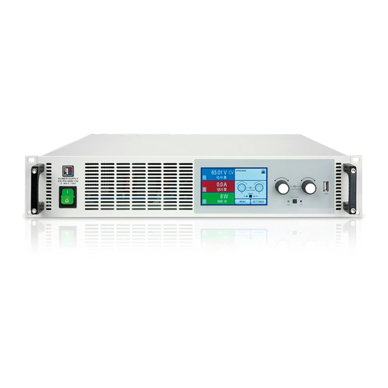
Page 112: Views
PSI 9000 2U Series 1.9.4 Views Figure 1 - Front side Figure 2 - Rear side EA Elektro-Automatik GmbH Fon: +49 2162 / 3785-0 www.elektroautomatik.de Page 22 Helmholtzstr. 31-33 • 41747 Viersen Fax: +49 2162 / 16230 ea1974@elektroautomatik.de Germany... - Page 113 PSI 9000 2U Series EA Elektro-Automatik GmbH Fon: +49 2162 / 3785-0 www.elektroautomatik.de Page 23 Helmholtzstr. 31-33 • 41747 Viersen Fax: +49 2162 / 16230 ea1974@elektroautomatik.de Germany...
- Page 114 PSI 9000 2U Series Figure 5 - View from above, with DC cover (terminal type 1) EA Elektro-Automatik GmbH Fon: +49 2162 / 3785-0 www.elektroautomatik.de Page 24 Helmholtzstr. 31-33 • 41747 Viersen Fax: +49 2162 / 16230 ea1974@elektroautomatik.de Germany...
- Page 115 PSI 9000 2U Series Figure 6 - Control Panel Overview of the elements of the operating panel For a detailed description see section „1.10.6. The control panel (HMI)“ and „1.10.6.2. Pushbuttons“. Touchscreen display (resistive) Used for selection of set values, menus, conditions and display of actual values and status.
-
Page 116: Construction And Function
1.10.1 General description The electronic high performance power supplies of the PSI 9000 2U series are especially suitable for test systems and industrial controls due to their compact construction in a 19” enclosure with 2 height units (2U). Apart from basic functions of power supplies, set point curves can be produced in the integrated function generator (sine, rectangular, triangular and other curve types). Arbitrary curves can be saved to and loaded from a USB flash drive. -
Page 117: Scope Of Delivery
PSI 9000 2U Series 1.10.3 Scope of delivery 1 x Power supply device PSI 9000 2U 1 x Mains cord, 2 m, Euro plug (Schuko) and/or UK plug (depending on shipping destination) 1 x Printed operating guide 1 x Share Bus plug (separately or plugged) 1 x Remote sensing plug (separately or plugged) 1 x USB cable, 1.8 m... -
Page 118: The Control Panel (Hmi)
PSI 9000 2U Series 1.10.6 The control panel (HMI) The HMI (Human Machine Interface) consists of a display with touchscreen, two rotary knobs, a pushbutton and a USB-A port. 1.10.6.1 Touchscreen display The graphic touchscreen display is divided into a number of areas. The complete display is touch sensitive and can be operated by finger or stylus to control the equipment. - Page 119 PSI 9000 2U Series • Status display (upper right) This area displays various status texts and symbols: Display Description Locked The HMI is locked Unlocked The HMI is unlocked Output ON DC output is switched on Output OFF DC output is switched off Remote The device is under remote control from..
- Page 120 PSI 9000 2U Series 1.10.6.3 Rotary knobs As long as the device is in manual operation, the two rotary knobs are used to adjust set values, as well as setting the parameters in the pages SETTINGS and MENU. For a detailed description of the individual functions see section „3.3 Manual operation“...
-
Page 121: Usb Port (Rear Side)
PSI 9000 2U Series 1.10.7 USB port (rear side) The USB-B port on the back side of the device is provided for communication with the device and for firmware updates. The included USB cable can be used to connect the device to a PC (USB 2.0 or 3.0). The driver is delivered on the included CD and installs a virtual COM port. -
Page 122: 1.10.10 Share Bus-Connection
PSI 9000 2U Series 1.10.10 Share Bus-Connection The 2 pole WAGO socket (“Share”) on the back side of the device is provided for connection to equally named sockets on compatible power supplies series to achieve a balanced load current distribution during parallel connection. The socket is also used to connect the power supply to compatible electronic loads, in order to build a two-quadrants operation setup. -
Page 123: Installation & Commissioning
PSI 9000 2U Series Installation & commissioning Transport and storage 2.1.1 Transport • The handles on the front side of the device are not for carrying! • Because of its weight, transport by hand should be avoided where possible. If unavoidable then only the housing should be held and not on the exterior parts (handles, DC output terminal, rotary knobs). -
Page 124: Preparation
Preparation Mains connection for a PSI 9000 2U series device is done via the included 2 meters long 3 pole mains cord. In case a different AC wiring is required, make sure that the other cable has at least a cross section of 2.5 mm² (AWG 12) is used. -
Page 125: Connection To Ac Supply
PSI 9000 2U Series 2.3.4 Connection to AC supply • The device can be connected to any wall socket or multi-socket outlet, as long as those feature a safety contact (PE) and are capable for 16 A. • When connecting the device to a multi-socket outlet, along with other electric devices, it is important to consider the total power consumption of all devices on the outlet, so that the maximum current (power ÷ mininum voltage) does not exceed the definition for the wall socket,... -
Page 126: Grounding Of The Dc Output
PSI 9000 2U Series 2.3.5.2 Cable lead and plastic cover A plastic cover for contact protection is included for the DC terminal. It should always be installed. The cover for type 2 (see picture above) is fixed to the connector itself, for type 1 to the back of the device. Furthermore the cover for type 1 has break outs so that the supply cable can be laid in various directions. -
Page 127: Connection Of Remote Sensing
PSI 9000 2U Series 2.3.7 Connection of remote sensing In order to compensate, to a certain degree, the voltage loss in a DC cable, the device provides the possibility to connect the remote sensing input “Sense” (rear side) to the load. The device recognizes the remote sensing mode automatically and regulates the output voltage (only in CV operation) at the load rather than at its own DC output. In the technical specifications (see section „1.9.3. -
Page 128: Installation Of An Anybus Interface Module
PSI 9000 2U Series 2.3.8 Installation of an AnyBus interface module The various interface modules which are available for the device can be retrofitted by the user and are exchangeable with other modules. The settings for the currently installed module vary and need to be checked and, if necessary, corrected on initial installation and after module exchange. • Common ESD protection procedures apply when inserting or exchanging a module. -
Page 129: Connecting The "Share" Bus
PSI 9000 2U Series 2.3.10 Connecting the “Share” bus The “Share” bus connector on the back side is intended to balance the current of multiple units in parallel opera- tion, especially when using the integrated function generator of the master unit. It is recommended to connect the Share bus of any unit involved in parallel operation. -
Page 130: Operation And Application
PSI 9000 2U Series Operation and application Personal safety • In order to guarantee safety when using the device, it is essential that only persons operate the device who are fully acquainted and trained in the required safety measures to be taken when working with dangerous electrical voltages • For models which can generate a voltage which is dangerous by contact, or is connected to... -
Page 131: Power Regulation / Constant Power / Power Limiting
PSI 9000 2U Series 3.2.3 Power regulation / constant power / power limiting Power regulation, also known as power limiting or constant power (CP), keeps the DC output power of a power supply constant if the current flowing to the load in relation to the output voltage and the resistance of load reaches the adjusted value according to P = U * I resp. -
Page 132: Alarm Conditions
PSI 9000 2U Series 3.2.5 Alarm conditions This section only gives an overview about device alarms. What to do in case your device indi- cates an alarm condition is described in section „3.5. Alarms and monitoring“. As a basic principle, all alarm conditions are signalled optically (Text + message in the display), acoustically (if activated) and as a readable status via the digital interface. -
Page 133: Manual Operation
PSI 9000 2U Series Manual operation 3.3.1 Switching on the device The device should, as far as possible, always be switched on using the toggle switch on the front of the device. Alternatively this can take place using an external cutout (contactor, circuit breaker) of suitable current capacity. - Page 134 PSI 9000 2U Series EA Elektro-Automatik GmbH Fon: +49 2162 / 3785-0 www.elektroautomatik.de Page 44 Helmholtzstr. 31-33 • 41747 Viersen Fax: +49 2162 / 16230 ea1974@elektroautomatik.de Germany...
- Page 135 PSI 9000 2U Series EA Elektro-Automatik GmbH Fon: +49 2162 / 3785-0 www.elektroautomatik.de Page 45 Helmholtzstr. 31-33 • 41747 Viersen Fax: +49 2162 / 16230 ea1974@elektroautomatik.de Germany...
- Page 136 PSI 9000 2U Series EA Elektro-Automatik GmbH Fon: +49 2162 / 3785-0 www.elektroautomatik.de Page 46 Helmholtzstr. 31-33 • 41747 Viersen Fax: +49 2162 / 16230 ea1974@elektroautomatik.de Germany...
- Page 137 PSI 9000 2U Series 3.3.3.1 Menu “General Settings” Element P. Description Allow remote control Selection “NO” means that the device cannot be remotely controlled over either the digital or analog interfaces. If remote control is not allowed, the status will be shown as “local”...
- Page 138 PSI 9000 2U Series 3.3.3.5 Menu “About HW, SW...” This menu page displays an overview of device relevant data such as serial number, article number etc. 3.3.3.6 Menu “Function Generator” See „3.8 The function generator“ on page 61. 3.3.3.7 Menu “Communication”...
- Page 139 PSI 9000 2U Series IF Level 1 Level 2 Level 3 Description IP Settings DHCP The IF allows a DHCP server to allocate an IP address, a subnet mask and a gateway. If no DHCP server is in the network then net- work parameters will be set as defined in point “Manual”...
-
Page 140: Adjustment Limits (Limits)
PSI 9000 2U Series 3.3.3.8 Menu “HMI settings” These settings refer exclusively to the control panel (HMI). Element Description Language Selection of the display language. Currently (date: 04-14-2014) available are: German, English Additional languages (up to three can be integrated) can be implemented on demand and installed into the HMI via update. -
Page 141: Changing The Operating Mode
PSI 9000 2U Series 3.3.5 Changing the operating mode In general, the manual operation of a PSI 9000 2U distinguishes between two operating modes which are tied to set value input using the rotary knobs or ten-key pad. This assignment must be changed if one of the three set values is to be adjusted which is currently not available. - Page 142 PSI 9000 2U Series ►How to adjust values U, I or P via direct input: In the main screen, depending on the rotary knob assignment, values can be set for voltage (U), current (I) or power (P) via direct input by tapping on the set/actual value display areas, e.g in the uppermost area...
-
Page 143: Switching The Dc Output On Or Off
PSI 9000 2U Series 3.3.7 Switching the DC output on or off The DC output of the device can be manually or remotely switched on and off. This can be restricted in manual operation by the control panel being locked. -
Page 144: Remote Control Via A Digital Interface
PSI 9000 2U Series 3.4.3 Remote control via a digital interface 3.4.3.1 Selecting an interface The device supports, in addition to the built-in USB port, the following optional interface modules for user preference: Short ID Art. nr. Type Ports Description*... -
Page 145: Remote Control Via The Analog Interface (Ai)
PSI 9000 2U Series 3.4.4 Remote control via the analog interface (AI) 3.4.4.1 General The built-in, up to 1500 V DC galvanically isolated 15-pole analog interface (short: AI) is on the rear side of the device offers the following possibilities: • Remote control of current, voltage and power... - Page 146 PSI 9000 2U Series 3.4.4.3 Analog interface specification Pin Name Type* Description Levels Electrical properties 0…10 V or. 0...5 V correspond VSEL Set voltage value Accuracy < 0.2% to 0..100% of U 0…10 V or. 0...5 V correspond Input impedance R >40 kΩ...100 kΩ...
- Page 147 PSI 9000 2U Series 3.4.4.5 Application examples a) Switching off output with pin “Rem-SB” The pin Rem-SB can be used in remote control to switch the output on and off. It is recom- mended that a low resistance contact such as a switch, relay or transistor is used to switch the pin to ground (DGND).
-
Page 148: Alarms And Monitoring
PSI 9000 2U Series Alarms and monitoring 3.5.1 Definition of terms There is a clear distinction between device alarms (see „3.2.5. Alarm conditions“) such as overvoltage protection or overheating protection, and user defined events such as OVD (overvoltage detection). Whilst device alarms serve to protect the device and the connected load by initially switching off the DC output, user defined events can switch off the DC output (Action = ALARM), but can also simply give an acoustic signal to make the user aware. - Page 149 PSI 9000 2U Series Alarm Meaning Description Indication OverTem- Triggers an alarm if the internal temperature exceeds a certain limit. The Display, analog perature DC output will be switched off. IF, digital IF ► How to configure the device alarms Tap the touch area on the main screen.
-
Page 150: Control Panel (Hmi) Lock
PSI 9000 2U Series As soon as an event is set up with an action other than “NONE” and with accepted settings, an incident can occur whether the DC output is switched on or off. On leaving the pages “User events” or “Settings” an event can be directly displayed. -
Page 151: The Function Generator
PSI 9000 2U Series The function generator 3.8.1 Introduction The built-in function generator is, like the equally named electronic devices, able to create various signal forms and apply these to set values for voltage or current. Whilst R mode is activated, access to the function generator is not available. -
Page 152: Manual Operation
PSI 9000 2U Series 3.8.4 Manual operation 3.8.4.1 Function selection and control Via the touchscreen one of the functions described above can be called up, configured and controlled. Selection and configuration are only possible when the output is switched off. ► How to select a function and adjust parameters Tap the touch area on the main screen. -
Page 153: Sine Wave Function
PSI 9000 2U Series ► How to start and stop a function The function can be started either by tapping or pushing the “On/Off” button, if the DC output is currently switched off. The function then starts immediately. In case START is used while the DC output is still switched off, the DC output will be switched on automatically. -
Page 154: Rectangular Function
PSI 9000 2U Series Schematic diagram: Application and result: A triangular wave signal for output current (only effective in current limiting) or output voltage is generated. The positive and negative slope times are variable and can be set independently. The offset shifts the signal on the Y-axis. -
Page 155: Trapezoidal Function
PSI 9000 2U Series 3.8.8 Trapezoidal function The following parameters can be configured for a trapezoidal curve function: Value Range Description I(A), U(A) 0...(Nominal value - (Off)) of U, I A = Amplitude of the signal to be generated I(Off), U(Off) 0...(Nominal value - (A)) of U, I Off = Offset, based on the foot of the trapezium 0.1 ms...36000 s... -
Page 156: Arbitrary Function
PSI 9000 2U Series 3.8.10 Arbitrary function The arbitrary (freely definable) function offers the user further scope. Up to 100 sequences are available for use for current I and voltage U, all of which have the same parameters but which can be differently configured so that a complex function process can be built up. The 100 sequences can run one after another in a sequence block, and this sequence block can then be repeated many times or endlessly. From the 100 sequences a block can be freely defined to run from sequence x to sequence y. A mix of assignment to current I or voltage U is not possible;... - Page 157 PSI 9000 2U Series Schematic diagram: Applications and results: Example 2 Focussing 1 cycle of 1 sequence from 100: The DC values at start and end are the same but the AC (amplitude) not. The end value is higher than the start so that the amplitude increases with each new half sine wave continuously through the sequence.
- Page 158 PSI 9000 2U Series By linking together a number of differently configured sequences, complex progressions can be created. Smart configuration of the arbitrary generator can be used to match triangular, sine, rectangular or trapezoidal wave func- tions and thus, e.g. a sequence of rectangular waves with differing amplitudes or duty cycles could be produced. Assignment to either U or I makes up to 100 sequences available for either current or voltage but not a mix.
- Page 159 PSI 9000 2U Series 3.8.10.1 Loading and saving the arbitrary function The 100 sequences of the arbitrary function, which can be manually configured with the control panel of the device and which are applicable either to voltage (U) or current (I), can be saved to or loaded from a common USB flash drive via the front side USB port. Generally, all 100 sequences are saved or loaded using a text file of type CSV (semicolon separator), which represents a table of values. In order to load a sequence table for the arbitrary generator, following requirements have to be met: • The table must contain exactly 100 rows with 8 subsequent values (8 columns, separated by semicolons) and must not have gaps • The files must be stored inside a folder called HMI_FILES which has to be in the root of the USB drive...
-
Page 160: Ramp Function
PSI 9000 2U Series ► How to save a sequence table (100 sequences) to a USB flash drive: Do not plug the USB flash drive yet or remove it. Access the function selection menu of the function generator via MENU -> Function Generator -> Arbitrary Tap on , then . The device will request you to plug the USB flash drive now. - Page 161 PSI 9000 2U Series In the IU function the assignment of the values is the other way round, the behaviour, however, the same. Thus the behaviour of the load or the current and power consumption can be controlled with dependance on output voltage and step changes can be created.
-
Page 162: Pv Table Function (Photovoltaics)
PSI 9000 2U Series 3.8.13 PV table function (photovoltaics) 3.8.13.1 Preface This function uses the standard XY generator to make the power supply simulate solar panels or solar cells with certain characteristics. The device calculates an IU table from four typical values. -
Page 163: Fc Table Function (Fuel Cell)
PSI 9000 2U Series Varying this parameter shifts the MPP and the PV curve along the Y axis. Also see diagram to the right. The value Irradiance is here used as a factor for the current Impp. The curve itself is not permanently re-calculated. - Page 164 PSI 9000 2U Series 3.8.14.2 Usage The following parameters can be set for the FC table function: Value Range Description Point 1: Uoc 0 V...U Open circuit voltage at no load Point 2+3: U 0 V...U Voltage and current define the position of these two points in the U-I coordinate system, which represent two support- Point 2+3: I 0 A...I...
-
Page 165: Remote Control Of The Function Generator
PSI 9000 2U Series 3.8.15 Remote control of the function generator The function generator can be remotely controlled but configuration and control of the functions with individual commands is different from manual operation. The external documentation “Programming Guide ModBus & SCPI” explains the approach. In general the following apply: • The function generator is not controllable via the analog interface • The function generator is unavailable if the device is in master-slave mode or R mode is activated... -
Page 166: Other Applications
PSI 9000 2U Series Other applications 3.9.1 Parallel operation in master-slave mode (MS) Multiple devices of same kind and model can be connected in parallel in order to create a system with higher total current and hence higher power. For true master-slave operation, the units have to be connected with their DC outputs, their master-slave bus and their Share bus. - Page 167 PSI 9000 2U Series The two units at the beginning and end of the chain should be terminated, if long connection cables are used. This is achieved using a 3-pole DIP switch which is positioned on the back side of the unit next to the MS connectors.
- Page 168 PSI 9000 2U Series 3.9.1.4 Operating the master-slave system After successful configuration and initialisation of the master and slave units, these will show their status in the displays. While the master merely shows “Master” in the status area, the slave(s) will continuously show like this, as long they are in remote control by the master: The slaves can no longer be controlled manually or remotely, neither via the analog nor via digital interfaces. They can, if needed, be monitored by reading actual values and status.
-
Page 169: Series Connection
PSI 9000 2U Series 3.9.2 Series connection Series connection of two or multiple devices is basically possible. But for reasons of safety and isolation, some restrictions apply: • Both, negative (DC-) and positive (DC+) output poles, are coupled to PE via type X capacitors • None DC minus pole of any in the series connection must have a potential of >400 V against... -
Page 170: Two Quadrant Operation (2Qo)
PSI 9000 2U Series 3.9.3 Two quadrant operation (2QO) 3.9.3.1 Introduction This way of operating refers to the use of a source, in this case a power supply of this series PSI 9000 2U, and a sink, for example a series ELR 9000 electronic load. - Page 171 PSI 9000 2U Series Configuration C: E-LOAD n PSU n Multiple e-loads and Multiple power supplies, plus 1 test object (E.U.T), for raising the total performance. The load combination and the power supply combination Share- E-LOAD 1 PSU 1 create in each case a total system with a defined power. It is necessary also here to match the nominal values of the two systems.
-
Page 172: Service And Maintenance
PSI 9000 2U Series Service and maintenance Maintenance / cleaning The device needs no maintenance. Cleaning may be needed for the internal fans, the frequency of cleanse is depending on the ambient conditions. The fans serve to cool the components which are heated by the inherent power loss. Heavily dirt filled fans can lead to insufficient airflow and therefore the DC output would switch off too... -
Page 173: Firmware Updates
PSI 9000 2U Series Firmware updates 4.3.1 HMI update The control panel (HMI) can be updated via the front or back USB ports, whereby the back USB port requires a PC with suitable software and the front USB only requires a FAT32 formatted USB flash drive with the update file. Hence the latter option is much simpler. Firmware updates should only be installed when they can eliminate software bugs in the firmware of your device or contain new features. -
Page 174: Calibration
PSI 9000 2U Series Calibration 4.4.1 Preface The devices of series PSI 9000 feature a function to readjust the most important output values when doing a cali- bration and in case these values have moved out of tolerance. The readjustment is limited to compensate small differences of up to 1% or 2% of the max. - Page 175 PSI 9000 2U Series ► How to calibrate the voltage Connect a multimeter to the DC output. Connect a load and set it to less than 5% of the nominal current of the power supply as load current, in this example let’s use 5 A.
-
Page 176: Accessories And Options
PSI 9000 2U Series Accessories and options Overview Accessories and options are, when necessary, delivered with their own documentation and are not detailed further in this document. Service & Support General Repairs, if not otherwise arranged between supplier and customer, will be carried out by the manufacturer. For this the device must generally be returned to the manufacturer. No RMA number is needed. It is sufficient to package... - Page 178 EA-Elektro-Automatik GmbH & Co. KG Entwicklung - Produktion - Vertrieb Helmholtzstraße 31-33 41747 Viersen Telefon: 02162 / 37 85-0 Telefax: 02162 / 16 230 ea1974@elektroautomatik.de www.elektroautomatik.de...
Need help?
Do you have a question about the PSI 9000 2U Series and is the answer not in the manual?
Questions and answers